
This article explores STM32 ADC operation using Polling, Interrupt, and DMA modes. We will demonstrate the configuration of each mode and their advantages for effective data acquisition.

Things used in this project
Software apps and online services:
1- STMicroelectronics STM32CubeMX
2- STMicroelectronics STM32CubeIDE
3- Proteus 8
Implementation of PWM-Based LED Brightness Control Using STM32 Microcontroller and ADC Integration
The project involves controlling the brightness of an LED using PWM. The STM32 microcontroller will generate a PWM signal using the TIMER peripheral and output it to an LED connected to a GPIO pin. The duty cycle of the PWM signal will be determined by the analog voltage level from an ADC channel connected to a potentiometer.
To implement this system, we can use three different methods to read the ADC result and set the PWM duty cycle using ADC Polling, Interrupt, and DMA modes :
ADC is used in blocking mode (polling):
In this method, the microcontroller will continuously check the status of the ADC channel in a blocking manner. When the ADC conversion is complete, the microcontroller will move the result to the timer CCR register to set the PWM duty cycle. This ADC Polling method is simple and easy to implement but can be less efficient and may block
ADC is used in non-blocking mode (Interrupt):
In this method, the microcontroller will configure the ADC to generate an interrupt when the conversion is complete. When the interrupt occurs, the microcontroller will move the result to the timer CCR register to set the PWM duty cycle. This ADC Interrupt method is more efficient and allows other tasks to execute while waiting for the ADC conversion.
ADC is used in non-blocking mode (DMA): :
In this method, the microcontroller will configure the DMA to transfer the ADC result directly to the timer CCR register. This method is the most efficient as it eliminates the need for CPU intervention in moving the ADC result to the timer CCR register.
To get started with this project, we can begin by configuring the ADC to read the analog voltage level from the potentiometer. We can then configure the TIMER peripheral in PWM mode to output the signal to the LED. Next, we can implement the three different methods for reading the ADC result and moving it to the timer CCR register to set the PWM duty cycle.Additionally, we will simulate the circuit design using Proteus software to test the project before implementing it in hardware.
STM32CubeMX Configuration:
- Open CubeMX & Create New Project Choose The Target MCU STM32F103C6 & Double-Click Its Name
- Go To The Clock Configuration & Set The System Clock To 8MHz
Configuration for the ADC PLL,IT,DMA Modes:
- In the Categories tab, select the ADC1 & enable IN7
- In the Parameter settings tab, Enable the Continuous Conversion Mode
- In the NVIC settings tab, Enable ADC1 and ADC2 global Interrupts
- In the DMA settings tab, enable the DMA for the ADC1 Channel 1
Configuration for the TIMER PWM Mode:
- In the Categories tab, select the TIM2 & enable (Internal Clock & PWM Generation Channel 2)
- In the Parameter settings tab, set the Counter Peroid = 65535
- Generate The Initialization Code & Open The Project In CubeIDE
- Write The Application Layer Code
STM32CubeIDE Configuration :
In file name : main.c
#include "main.h"

/* USER CODE BEGIN PV */
uint16_t ADC_VAL = 0 ;
/* USER CODE END PV */

/* USER CODE BEGIN 0 */
 void HAL_ADC_ConvCpltCallback(ADC_HandleTypeDef* hadc)
{
   //callBacK IT
   if(HAL_GPIO_ReadPin(GPIOB, GPIO_PIN_1)==GPIO_PIN_SET)
       {
       //Read and update the ADC Result
     ADC_VAL = HAL_ADC_GetValue(&hadc1);
       }
   //CallBack DMA
   else if(HAL_GPIO_ReadPin(GPIOB, GPIO_PIN_2)==GPIO_PIN_SET)
       {
         // Conversion complete and DMA Transfer as well
        //=> Update the PWM Duty Cycle whit the last ADC Conversion Result
     TIM2->CCR2 = (ADC_VAL<<4);
       }

}
/* USER CODE END 0 */

int main(void)
{
  HAL_Init();
  SystemClock_Config();
  MX_GPIO_Init();
  MX_DMA_Init();
  MX_ADC1_Init();
  MX_TIM2_Init();

  /* USER CODE BEGIN 2 */
HAL_TIM_PWM_Start(&htim2, TIM_CHANNEL_2);
//Calibrate the ADC on Power-up for better Accuracy
HAL_ADCEx_Calibration_Start(&hadc1);
  /* USER CODE END 2 */

while (1)
{
//Polling Mode
if(HAL_GPIO_ReadPin(GPIOB, GPIO_PIN_0)==GPIO_PIN_SET)
{
 HAL_ADC_Start(&hadc1);                   //Start ADC Conversion
 HAL_ADC_PollForConversion(&hadc1, 1);//Poll ADC1  and Timeout =1mSec
 ADC_VAL = HAL_ADC_GetValue(&hadc1);      // Read the ADC Conversion Result
      TIM2->CCR2 = (ADC_VAL<<4);
      HAL_Delay(1);
}
 //IT Mode
 else if(HAL_GPIO_ReadPin(GPIOB, GPIO_PIN_1)==GPIO_PIN_SET)
 {
 HAL_ADC_Start_IT(&hadc1);  //Start ADC Conversion IT
 TIM2->CCR2 = (ADC_VAL<<4);//update PWM Duty Cycle whit the latest Conversion
 HAL_Delay(1);
 }
//DMA Mode
else if(HAL_GPIO_ReadPin(GPIOB, GPIO_PIN_2)==GPIO_PIN_SET)
{
HAL_ADC_Start_DMA(&hadc1, (uint32_t*)&ADC_VAL, 1); //Start ADC Conversion DMA
HAL_Delay(1);
}
else{
 HAL_ADC_Stop(&hadc1);
 HAL_ADC_Start_IT(&hadc1);
 HAL_ADC_Stop_DMA(&hadc1);
 }
}
  /* USER CODE END 3 */
}
Proteus Configuration :
- Open Proteus & Create New Project and click next

- Click on Pick Device
- Search for STM32F103C6 & SW-SPDT & SW-ROT3 & POT & (LED_RED, BlUE, PINK)
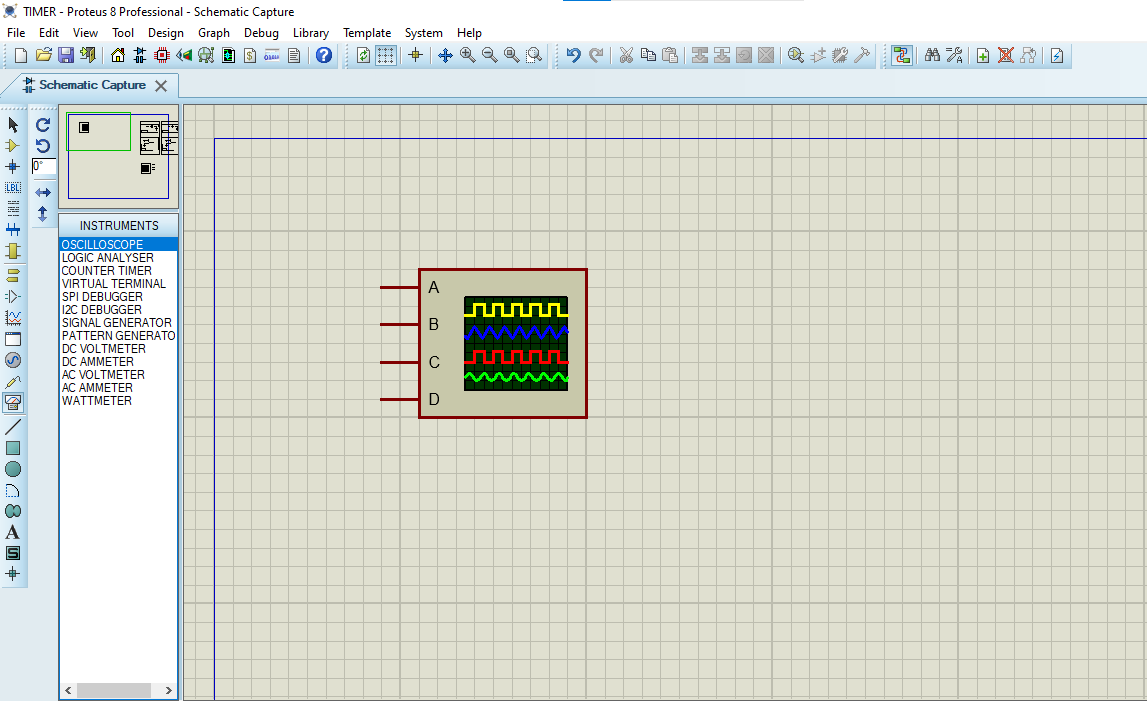
- Click on Virtual Instruments Mode then choose OSCILLOSCOPE
- Click on Terminal Mode then choose (DEFAULT & POWER &GROUND)
- finally make the circuit below and start the simulation
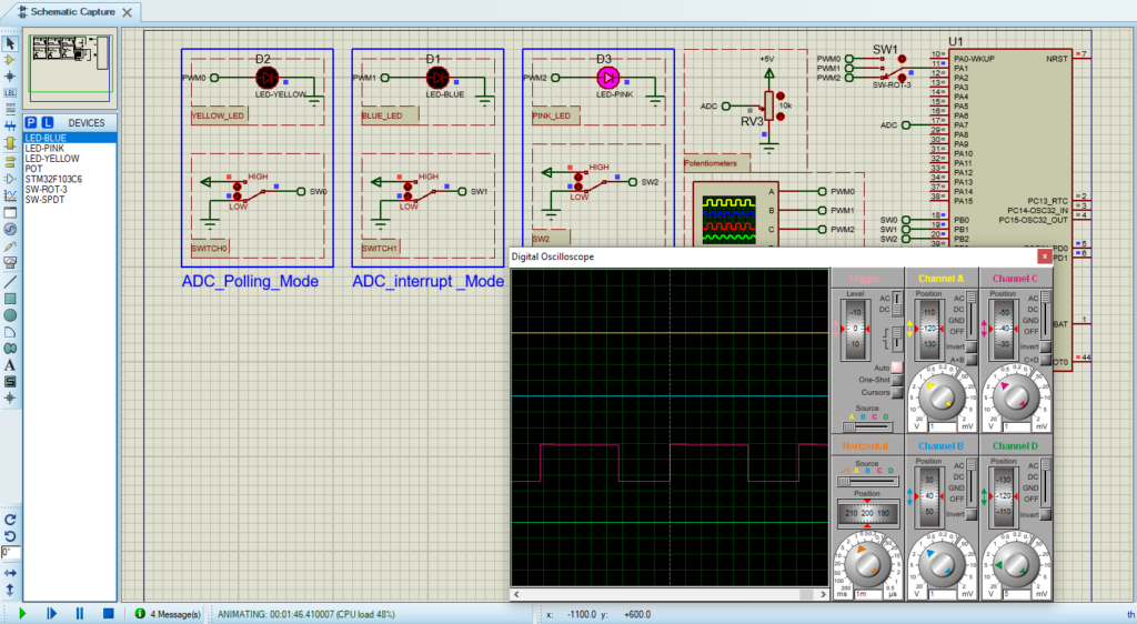
That’s all!
If you have any questions or suggestions don’t hesitate to leave a comment below
2 comments
[…] project aims to investigate how external triggers enhance STM32 ADC functionality. By exploring how ADC conversions can be synchronized with external events, we seek to understand their impact on analog […]
[…] configuring the external trigger conversion source, developers gain flexibility in tailoring the ADC operation to suit specific application […]