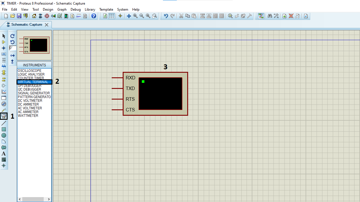
Advanced Analog-to-Digital Conversion : STM32 ADC Scan Mode

by marwen maghrebi

Things used in this project

Software apps and online services

1- STMicroelectronics STM32CubeMX

2- STMicroelectronics STM32CubeIDE

3- Proteus 8

This project delves into the STM32 ADC Scan Mode, a crucial tool for automating analog channel acquisition in embedded systems. Similar to a conductor guiding an orchestra, Scan Mode automates the process, smoothly moving from one channel to the next without manual intervention.

Streamlining Conversion Process with Scan Mode:

With Scan Mode, developers can streamline the conversion process, saving time and effort by eliminating the need for constant configuration between channel conversions. By specifying the number of conversions and configuring the external trigger conversion source, developers gain flexibility in tailoring the ADC operation to suit specific application requirements.

Maximizing Efficiency with DMA Integration:

Integration with the DMA controller is essential for maximizing Scan Mode benefits. Enabling the DMA bit automates data transfer to SRAM after each conversion, reducing CPU workload and enabling efficient multitasking and real-time data processing.

Practical applications of STM32 ADC Scan Mode are diverse, spanning industries like industrial automation and sensor monitoring. By understanding and implementing Scan Mode effectively, developers can enhance system efficiency and reliability in embedded systems projects.

To initiate this project, we’ll start by enabling ADC Scan Conversion mode, followed by configuring the ADC conversion in regular mode. Finally, we’ll set up UART communication to transmit both the ADC readings and system status

STM32CubeMX Configuration:

  • Open CubeMX & Create New Project Choose The Target MCU STM32F103C6 & Double-Click Its Name
  • Go To The Clock Configuration & Set The System Clock To 8MHz

Configuration for the GPIO Mode:

  • Configure GPIO Pins PA1 and PA2 as Output Pins, with one indicating the loop status and the other for callback notifications.

Configuration for the ADC Mode:

  • In the Categories tab, select the [ADC1, enable IN8 & IN9]
  • In the Parameter settings tab, ADC Settings : Enable Scan Conversion Mode
  • In the Parameter settings tab, ADC_Regular_ConversionMode: [Enabler Regular Conversion Mode & Number of Conversio :2 & External Trigger Conversion source : Regular Conversion launched by software& Rank1, Rank2 : channel : 8, 9, sympling Time 1.5 Cycles]
  • In the DMA settings tab, enable the DMA for the ADC1 Channel 1
  • In the NVIC settings tab, Enable [ADC1 and ADC2 global interrupts & DMA1 channel1 global interrupt]

Configuration for the UART Mode:

  • Enable USART1 Module (Asynchronous Mode)
  • Set the USART1 communication parameters (baud rate = 115200, parity=NON, stop bits =1, and word length =8bits)
  • Generate The Initialization Code & Open The Project In CubeIDE
  • Write The Application Layer Code

STM32CubeIDE Configuration:

In file name :main.c
/* Includes ------------------------------------------------------------------*/
#include "main.h"
#include<stdio.h>
#include<string.h>

/* Private variables ---------------------------------------------------------*/
ADC_HandleTypeDef hadc1;
DMA_HandleTypeDef hdma_adc1;
UART_HandleTypeDef huart1;

/* Private function prototypes -----------------------------------------------*/
void SystemClock_Config(void);
static void MX_GPIO_Init(void);
static void MX_DMA_Init(void);
static void MX_ADC1_Init(void);
static void MX_USART1_UART_Init(void);

/* Private user code ---------------------------------------------------------*/
/* USER CODE BEGIN 0 */
char MSG[50];
uint16_t ADC_VAL[2];
volatile int adcConvertionComplete=0;
void HAL_ADC_ConvCpltCallback(ADC_HandleTypeDef* hadc)
{
adcConvertionComplete=1;
HAL_GPIO_WritePin(GPIOA, GPIO_PIN_1, 0);
HAL_GPIO_WritePin(GPIOA, GPIO_PIN_0, 1);
}
/* USER CODE END 0 */


int main(void)
{

HAL_Init();
SystemClock_Config();
MX_GPIO_Init();
MX_DMA_Init();
MX_ADC1_Init();
MX_USART1_UART_Init();

while (1)
   {
    HAL_ADC_Start_DMA(&hadc1, (uint32_t*)ADC_VAL, 2);
    while(adcConvertionComplete==0){}
    adcConvertionComplete==0;
    snprintf(MSG,sizeof(MSG),"ADC SCAN Channels =  %d\n\r",ADC_VAL[0]);
    HAL_UART_Transmit(&huart1, MSG, strlen(MSG), HAL_MAX_DELAY);
    HAL_GPIO_WritePin(GPIOA, GPIO_PIN_1, 1);
    HAL_GPIO_WritePin(GPIOA, GPIO_PIN_0, 0);
    HAL_Delay(1000);
   }

}

Step Two:

  • Open Proteus & Create New Project and click next
  • Click on Pick Device
  • Search for STM32F103C6 & POT & LED_RED & LED_GREEN  
  • Click on Virtual Instruments Mode then choose VIRTUAL TERMINAL
  • Click on Terminal Mode then choose (DEFAULT & POWER &GROUND)
  • finally make the circuit below and start the simulation
 

That’s all!

If you have any questions or suggestions don’t hesitate to leave a comment below

You Might Also Like

Leave a Comment


Are you sure want to unlock this post?
Unlock left : 0
Are you sure want to cancel subscription?
-
00:00
00:00
Update Required Flash plugin
-
00:00
00:00