
In this article, we’ll cover how to interface the STM32 ADC with the ACS712 Hall Effect-Based Current Sensor for accurate current measurement.
Things used in this project
Software apps and online services
1- STMicroelectronics STM32CubeMX
2- STMicroelectronics STM32CubeIDE
3- Proteus 8
Exploring Precision Power Monitoring with STM32 ADC and ACS712 Sensor
This project explores the precision power monitoring capabilities facilitated by the STM32 ADC in conjunction with the ACS712 Hall Effect-Based Current Sensor. Much like a skilled conductor guiding an orchestra, this combination harmoniously integrates to deliver precise and efficient power monitoring solutions in embedded systems.
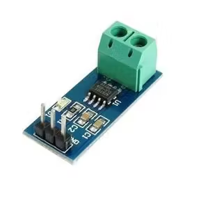
Precision Measurements with ACS712 Current Sensor:
The ACS712 sensor can be used by developers to make power monitoring easier with the STM32 ADC at its core. By combining the ADC‘s strong features with the ACS712‘s precise measurements, analyzing power usage in embedded systems can be made simpler and more reliable.
Real-Time Power Consumption Monitoring:
This integration enables real-time monitoring of power consumption across diverse applications. By optimizing the ADC‘s configuration and utilizing the ACS712‘s accurate measurements, developers can tailor power monitoring solutions to meet specific project requirements effectively.
From industrial automation to IoT deployments, the STM32 ADC and ACS712 Hall Effect-Based Current Sensor present a robust solution for mastering power monitoring in embedded systems.
To begin this project, we’ll first activate Continuous Conversion mode. Next, we’ll set up the ADC for regular mode conversion. Finally, we’ll establish UART communication to send out both the ADC readings and system status
STM32CubeMX Configuration:
- Open CubeMX & Create New Project Choose The Target MCU STM32F103C6 & Double-Click Its Name
- Go To The Clock Configuration & Set The System Clock To 8MHz
Configuration for the ADC Mode:
- In the Categories tab, select the [ADC1, enable IN9]
- In the Parameter settings tab, ADC Settings : Enable Continuous Conversion Mode
- In the Parameter settings tab, ADC_Regular_Conversion Mode: [Enabler Regular Conversion Mode & Number of Conversio : 1 & External Trigger Conversion source : Regular Conversion launched by software & Rank1: channel : 9, sympling Time :1.5 Cycles]
Configuration for the UART Mode:
- Enable USART1 Module (Asynchronous Mode)
- Set the USART1 communication parameters (baud rate = 115200, parity=NON, stop bits =1, and word length =8bits)
- Generate The Initialization Code & Open The Project In CubeIDE
- Write The Application Layer Code
STM32CubeIDE Configuration:
/* Includes ------------------------------------------------------------------*/
#include "main.h"

* Private variables ---------------------------------------------------------*/
ADC_HandleTypeDef hadc1;
UART_HandleTypeDef huart1;

/* USER CODE BEGIN PV */
uint16_t readValue;
uint8_t MSG[100];

float sensitivity = 0.185; //0.185 for 5A module => datasheet
float actual_voltage;     //0A -->Vcc*0.5 = 5*0.5 = 2.5V => datasheet
float current ;
float Input_votage_range =3.3; //3.3v stm32
int ADC_range = 4095;
/* USER CODE END PV */

/* Private function prototypes -----------------------------------------------*/
void SystemClock_Config(void);
static void MX_GPIO_Init(void);
static void MX_ADC1_Init(void);
static void MX_USART1_UART_Init(void);

int main(void)
{
  HAL_Init();
  SystemClock_Config();
  MX_GPIO_Init();
  MX_ADC1_Init();
  MX_USART1_UART_Init();

  /* USER CODE BEGIN 2 */
    if(HAL_ADC_Start(&hadc1)!=HAL_OK)
    {
      Error_Handler();
    }
  /* USER CODE END 2 */

  while (1)
  {
    while(HAL_ADC_PollForConversion(&hadc1, 1000)!=HAL_OK)
    {
      Error_Handler();
    }
readValue= HAL_ADC_GetValue(&hadc1);
//if acual_voltage is not 2.5 V => multiply by factor in my case it is 17.54
actual_voltage= (float) ((readValue* Input_votage_range)/ADC_range)*17.54;

current=(actual_voltage-2.5)/sensitivity;

sprintf(MSG,"readValue = %d || actual_voltage = %.2f || current value = %.2f\n\r",
readValue,actual_voltage,current);

HAL_UART_Transmit(&huart1, MSG, sizeof(MSG), 200);
HAL_Delay(1000);
 }
}
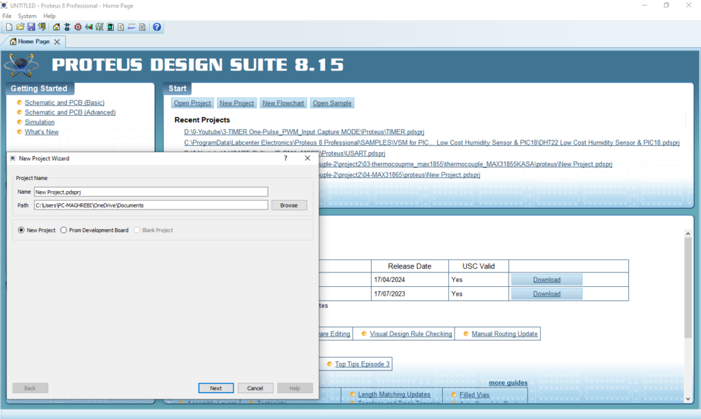
Proteus Configuration :
- Open Proteus & Create New Project and click next
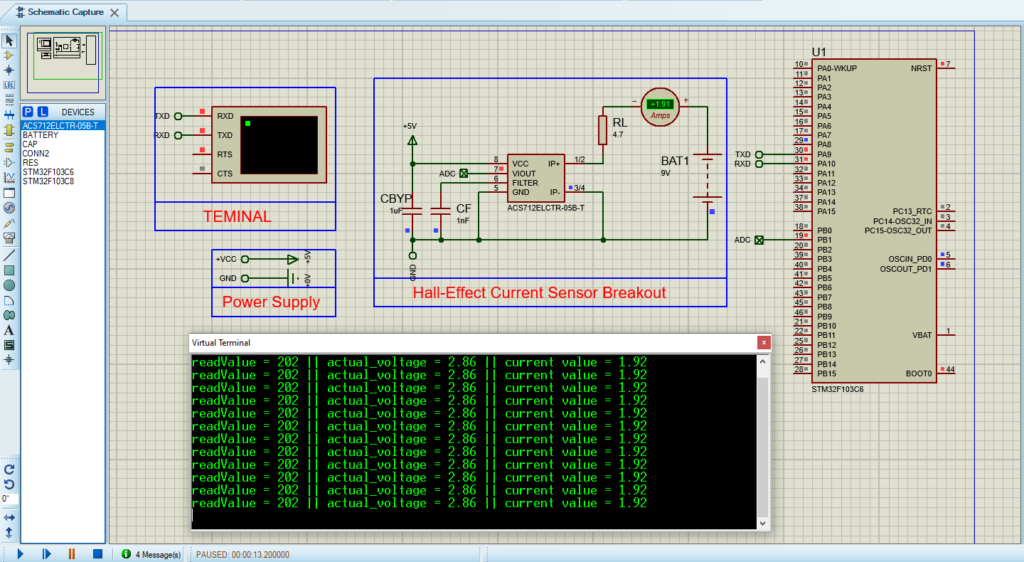
- Click on Pick Device
- Search for STM32F103C6 & ACS712 & BATTERY & CAP
- Click on Virtual Instruments Mode then choose VIRTUAL TERMINAL & DC AMPERMETRE
- Click on Terminal Mode then choose (DEFAULT & POWER &GROUND)
- finally make the circuit below and start the simulation
That’s all!
If you have any questions or suggestions don’t hesitate to leave a comment below
5 comments
[…] […]
Can you please share the Proteus files ? Thank you.
I will share them as soon as possible
can you please tell me why did you choose 17.54
Good question! I used 17.54 because I calibrated it using a voltmeter. I measured the actual voltage on the ADC pin and compared it to the calculated voltage from the formula. Then, I adjusted with this: (maxRealVoltage – minRealVoltage) / (maxActualVoltage – minActualVoltage). It’s a custom factor based on my setup to make the readings accurate. 😊