
In this article, we will explore the STM32 ADC Watchdog feature, an advanced method for enhancing analog-to-digital conversion processes.

Things used in this project
Software apps and online services
1- STMicroelectronics STM32CubeMX
2- STMicroelectronics STM32CubeIDE
3- Proteus 8
Exploring STM32 ADC Watchdog: Enhancing Reliability and Precision in Embedded Systems
This project focuses on exploring the STM32 ADCWatchdog, which operates akin to a vigilant window comparator integrated into the ADC operation. Tasked with monitoring voltage levels on AWD-enabled channels, it ensures adherence to predefined threshold levels. Upon detecting deviations beyond the programmed voltage window, the ADC Watchdog promptly triggers an interrupt, signaling potential anomalies.
Uniform Threshold Voltage Levels: Global Configuration Across All Channels :
Crucially, the threshold voltage levels remain uniform across all channels with AWD enabled, offering global configuration rather than channel-specific settings. While the analog watchdog feature can be activated individually for single regular channels, single injected channels, or across all ADC channels, its overarching purpose remains consistent: safeguarding analog input integrity in embedded systems.
Pivotal Role in Embedded Systems: Enhancing Reliability and Precision:
As we embark on this exploration of STM32 ADC Watchdog integration, we recognize its pivotal role in enhancing reliability and precision within embedded systems. Through structured experimentation and insightful analysis, we’ll uncover the practical applications and benefits of this indispensable feature. From industrial automation to IoT deployments, STM32 ADC Watchdog empowers developers to build resilient and responsive embedded solutions, solidifying their position as drivers of innovation in modern technology landscapes.
To initiate this project, we’ll start by configuring the ADC conversion in regular mode, seamlessly integrating the Analog Watchdog feature. Then, we’ll proceed to set up the interfacing aspect by configuring UART communication to transmit both the ADC readings and system status.
STM32CubeMX Configuration:
- Open CubeMX & Create New Project Choose The Target MCU STM32F103C6 & Double-Click Its Name
- Go To The Clock Configuration & Set The System Clock To 8MHz
Configuration for the GPIO Mode:
- Configure GPIO Pins PB0 and PB1 as Output Pins, with one indicating the loop status and the other for callback notifications.
Configuration for the ADC Mode:
- In the Categories tab, select the [ADC1, enable IN7]
- In the Parameter settings tab, [Enabler Regular Conversion Mode & Enable Analog Watchdog Mode & Set High and Low Threshold [4000 , 500]& Enable interrupt Mode ]
- In the NVIC settings tab, Enable ADC1 and ADC2 global Interrupts
Configuration for the UART Mode:
- Enable USART1 Module (Asynchronous Mode)
- Set the USART1 communication parameters (baud rate = 115200, parity=NON, stop bits =1, and word length =8bits)
- Generate The Initialization Code & Open The Project In CubeIDE
- Write The Application Layer Code
STM32CubeIDE Configuration:
In file name :main.c
#include "main.h"

/* Private variables ---------------------------------------------------------*/
ADC_HandleTypeDef hadc1;
UART_HandleTypeDef huart1;

/* Private function prototypes -----------------------------------------------*/
void SystemClock_Config(void);
static void MX_GPIO_Init(void);
static void MX_ADC1_Init(void);
static void MX_USART1_UART_Init(void);

/* Private user code ---------------------------------------------------------*/
/* USER CODE BEGIN 0 */
uint32_t ADC_VAL = 0;
uint8_t MSG[20];
uint8_t MSG2[50]="ERREUR YOUR ADC VAL IS > 4000 \n\r";
uint8_t MSG3[50]="ERREUR YOUR ADC VAL IS < 500 \n\r";
void HAL_ADC_LevelOutOfWindowCallback(ADC_HandleTypeDef * hadc)
{
ADC_VAL = HAL_ADC_GetValue(&hadc1);
if(ADC_VAL>3990))
{
HAL_UART_Transmit_IT(&huart1, MSG2, sizeof(MSG2));
}
else
HAL_UART_Transmit_IT(&huart1, MSG3, sizeof(MSG3));
HAL_GPIO_WritePin(GPIOB, GPIO_PIN_0, 0);
HAL_GPIO_WritePin(GPIOB, GPIO_PIN_1, 1);
}
/* USER CODE END 0 */

int main(void)
{
HAL_Init();
SystemClock_Config();
MX_GPIO_Init();
MX_ADC1_Init();
MX_USART1_UART_Init();

if(HAL_ADC_Start(&hadc1)!=HAL_OK)
    {
    Error_Handler();
    }

 while (1)
   {

    while(HAL_ADC_PollForConversion(&hadc1, 2)!=HAL_OK)
        {
        Error_Handler();
        }

    ADC_VAL = HAL_ADC_GetValue(&hadc1);
    sprintf(MSG,"ADC VAL = %u\n\r",ADC_VAL);
    HAL_UART_Transmit_IT(&huart1, MSG, sizeof(MSG));
    HAL_GPIO_WritePin(GPIOB, GPIO_PIN_1, 0);
    HAL_GPIO_TogglePin(GPIOB, GPIO_PIN_0);
    HAL_Delay(1000);
  }
}
Proteus Configuration :
- Open Proteus & Create New Project and click next

- Click on Pick Device
- Search for STM32F103C6 & POT & LED-GREEN & LED-REED
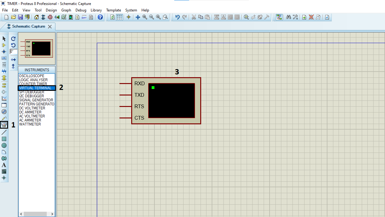
- Click on Virtual Instruments Mode then choose VIRTUAL TERMINAL
- Click on Terminal Mode then choose (DEFAULT & POWER &GROUND)
- finally make the circuit below and start the simulation.
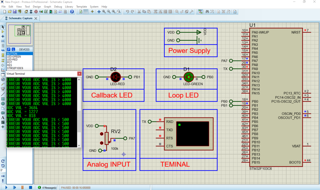
If you have any questions or suggestions don’t hesitate to leave a comment below