
In this article, we will explore the STM32 H-Bridge Motor Driver using the L298N module.
Things used in this project
Software apps and online services:
1- STMicroelectronics STM32CubeMX
2- STMicroelectronics STM32CubeIDE
3- Proteus 8
Interfacing STM32 with L298N Dual H-Bridge Motor Driver for DC Motor Control
In this project, we’ll explore how to interface an STM32 microcontroller with the L298N motor driver, allowing control over the speed and direction of two DC motors. The L298N is a versatile H-Bridge driver, making it ideal for projects involving motor control with STM32. We’ll walk through its pin configuration, key features, and how to integrate it into a real-world embedded system for controlling motor movement using PWM signals from the STM32.
L298N Overview:
The L298N is a dual H-Bridge motor driver module designed to control two DC motors simultaneously. It can handle voltages between 5V and 35V, with a peak current of up to 2A. The module has the following key features:
- Motor Power Supply (VCC): Provides power to the motors.
- Onboard 5V Regulator: Can be enabled (for motor voltages ≤12V) or disabled (for higher voltages) using a jumper.
- Logic Control Inputs (IN1, IN2, IN3, IN4): Control motor direction by switching the H-Bridge transistors.
Enable Pins (ENA, ENB): Enable and control the speed of the motors using PWM signals.
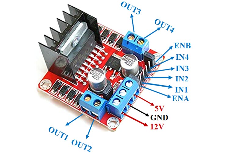
Pinout and Functionality:
The L298N module features two sets of screw terminals for motors A and B, along with terminals for ground, VCC (motor power), and a 5V pin that serves either as an output or input, depending on the motor supply voltage. Here’s how each pin works:
- ENA and ENB (Enable Pins): Enable motor A and B, respectively. When a jumper is present, the motor runs at full speed. You can connect these pins to PWM signals from the STM32 to control motor speed.
- IN1 and IN2 (Motor A Direction): These pins control the rotation direction of motor A. IN1 HIGH and IN2 LOW make the motor move forward; reversing the logic reverses the direction.
- IN3 and IN4 (Motor B Direction): Similar to IN1 and IN2, these control motor B.
Controlling H-Bridge DC Motors with an STM32 Microcontroller:
This guide provides an overview of how to control H-Bridge DC motors using an STM32 microcontroller. Following these steps will help you ensure proper operation and safeguard your components.
Required Components and Connections:
Gather the necessary components, including the STM32 microcontroller, an H-Bridge driver (such as L298N or equivalent), protection diodes, and resistors. Connect the GPIO pins from the STM32 to the “Forward” and “Reverse” inputs of the H-Bridge to manage the motor’s direction. Ensure that both the H-Bridge and the motor are powered appropriately. To protect against back EMF, integrate fast recovery diodes across the motor terminals.
Firmware Development
In the firmware, configure the GPIO pins as outputs and employ Pulse Width Modulation (PWM) for controlling the motor’s speed. This setup allows you to efficiently manage both the direction and speed of the H-Bridge DC motors, giving you precise control in your applications.
In this project, we will be leveraging an STM32 microcontroller alongside the L298 motor driver board to control two DC motors. The configuration will utilize GPIO pins and the TIM3 timer to generate PWM signals for precise motor control. The code will implement debouncing for user inputs, allowing us to manage the start/stop functions and adjust the duty cycle effectively. Furthermore, we will calculate the speeds of the motors and transmit their status via UART for real-time monitoring.
STM32CubeMX Configuration:
- Open CubeMX & Create New Project Choose The Target MCU STM32F103C6 & Double-Click Its Name
- Go To The Clock Configuration & Set The System Clock To 16MHz
Configuration for the TIMER Mode:
- In the Categories tab, select the TIM3 then Enable (Internal Clock & PWM Generation Channel 1 & PWM Generation Channel 3)
- In the Counter settings tab, set the (Prescaler = 0 & Counter Peroid = 65535)
- In the PWM Generation Channel set ( Mode : PWM mode 1 & Pulse = 0 )
Configuration for the GPIO Mode:
- Configure The GPIO Pins [PA1 , PA2 , PA3 , PA5 ,PA7 ,PA10] as Input Pins
- Configure The GPIO Pins [PA8 , PA9 ,PB12 , PB13 ] as Input Pins
Configuration for the UART Mode:
- Enable USART1 Module (Asynchronous Mode)
- Set the USART1 communication parameters (baud rate = 115200, parity=NON, stop bits =1, and word length = 8bits)
- Generate The Initialization Code & Open The Project In CubeIDE
STM32CubeIDE Configuration:
Initialization and Key Handling
In this section, we set up the necessary libraries, define GPIO pins for the motor control and user inputs, and implement the function to handle key presses. The checkKeys function reads the state of each key, debounces them, and updates the motor speeds based on user input.
/* Includes ------------------------------------------------------------------*/
#include "main.h"

/* Private includes ----------------------------------------------------------*/
/* USER CODE BEGIN Includes */
#include <stdlib.h>
#include <stdio.h>
#include <string.h>
/* USER CODE END Includes */

/* Private define ------------------------------------------------------------*/
/* USER CODE BEGIN PD */
// Key pins
#define KEY_PLUS_A_PIN GPIO_PIN_10
#define KEY_MINUS_A_PIN GPIO_PIN_1
#define KEY_BREAK_A_PIN GPIO_PIN_5
#define KEY_PLUS_B_PIN GPIO_PIN_2
#define KEY_MINUS_B_PIN GPIO_PIN_3
#define KEY_BREAK_B_PIN GPIO_PIN_7

// Motor Shield Pins
#define PWM_A_PIN GPIO_PIN_6
#define PWM_B_PIN GPIO_PIN_0
#define DIR_A_PIN GPIO_PIN_12
#define DIR_B_PIN GPIO_PIN_13
#define BRAKE_A_PIN GPIO_PIN_8
#define BRAKE_B_PIN GPIO_PIN_9

// PWM configuration
#define TIM_CLOCK_FREQ 16000000  // TIM3 clock frequency (assuming 72MHz system clock)
#define PWM_FREQUENCY 50        // Desired PWM frequency in Hz
#define TIM_PERIOD (TIM_CLOCK_FREQ / PWM_FREQUENCY) - 1
/* USER CODE END PD */

/* Private variables ---------------------------------------------------------*/
TIM_HandleTypeDef htim3;
UART_HandleTypeDef huart1;

/* USER CODE BEGIN PV */
// Motors Speed
int16_t speedA = 0;
int16_t speedB = 0;

// Old keys state for events triggering
uint8_t oldPlusA = 0, oldMinusA = 0, oldBreakA = 0;
uint8_t oldPlusB = 0, oldMinusB = 0, oldBreakB = 0;
/* USER CODE END PV */

/* Private function prototypes -----------------------------------------------*/
void SystemClock_Config(void);
static void MX_GPIO_Init(void);
static void MX_TIM3_Init(void);
static void MX_USART1_UART_Init(void);
/* USER CODE BEGIN PFP */

/* USER CODE END PFP */

/* Private user code ---------------------------------------------------------*/
/* USER CODE BEGIN 0 */
void checkKeys(void)
{
    // Keys Trigger
    uint8_t plusA = HAL_GPIO_ReadPin(GPIOA, KEY_PLUS_A_PIN) ? 0 : 1;
    if (plusA == oldPlusA)
        plusA = 0;
    else
        oldPlusA = plusA;

    uint8_t minusA = HAL_GPIO_ReadPin(GPIOA, KEY_MINUS_A_PIN) ? 0 : 1;
    if (minusA == oldMinusA)
        minusA = 0;
    else
        oldMinusA = minusA;

    uint8_t breakA = HAL_GPIO_ReadPin(GPIOA, KEY_BREAK_A_PIN) ? 0 : 1;
    if (breakA == oldBreakA)
        breakA = 0;
    else
        oldBreakA = breakA;

    uint8_t plusB = HAL_GPIO_ReadPin(GPIOA, KEY_PLUS_B_PIN) ? 0 : 1;
    if (plusB == oldPlusB)
        plusB = 0;
    else
        oldPlusB = plusB;

    uint8_t minusB = HAL_GPIO_ReadPin(GPIOA, KEY_MINUS_B_PIN) ? 0 : 1;
    if (minusB == oldMinusB)
        minusB = 0;
    else
        oldMinusB = minusB;

    uint8_t breakB = HAL_GPIO_ReadPin(GPIOA, KEY_BREAK_B_PIN) ? 0 : 1;
    if (breakB == oldBreakB)
        breakB = 0;
    else
        oldBreakB = breakB;

    // Keys Reaction
    if (plusA)
    {
        speedA += 50;
        if (speedA > 250)
            speedA = 250;
    }
    if (minusA)
    {
        speedA -= 50;
        if (speedA < -250)
            speedA = -250;
    }
    if (breakA)
        speedA = 0;
    if (plusB)
    {
        speedB += 50;
        if (speedB > 250)
            speedB = 250;
    }
    if (minusB)
    {
        speedB -= 50;
        if (speedB < -250)
            speedB = -250;
    }
    if (breakB)
        speedB = 0;
}
Motor Control and UART Communication
This section contains the updateMotors function that manages the PWM signal output and motor direction based on the current speed. It also includes the printSpeeds function to relay the current speed values over UART. The main function initializes the hardware components and continuously updates the motor states based on key inputs
void updateMotors(void)
{
    // Speed
    __HAL_TIM_SET_COMPARE(&htim3, TIM_CHANNEL_1, (uint32_t)(abs(speedA) * TIM_PERIOD / 255));
    __HAL_TIM_SET_COMPARE(&htim3, TIM_CHANNEL_3, (uint32_t)(abs(speedB) * TIM_PERIOD / 255));

    // Direction
    HAL_GPIO_WritePin(GPIOB, DIR_A_PIN, (speedA > 0) ? GPIO_PIN_SET : GPIO_PIN_RESET);
    HAL_GPIO_WritePin(GPIOB, DIR_B_PIN, (speedB > 0) ? GPIO_PIN_SET : GPIO_PIN_RESET);

    // Brake On/Off
    HAL_GPIO_WritePin(GPIOA, BRAKE_A_PIN, (speedA == 0) ? GPIO_PIN_SET : GPIO_PIN_RESET);
    HAL_GPIO_WritePin(GPIOA, BRAKE_B_PIN, (speedB == 0) ? GPIO_PIN_SET : GPIO_PIN_RESET);
}

void printSpeeds(void)
{
    char buffer[50];
    int len = sprintf(buffer, "Speed A = %d B = %d\r\n", speedA, speedB);
    HAL_UART_Transmit(&huart1, (uint8_t*)buffer, len, HAL_MAX_DELAY);
}

/* USER CODE END 0 */

/**
  * @brief  The application entry point.
  * @retval int
  */
int main(void)
{
    /* USER CODE BEGIN 1 */
    /* USER CODE END 1 */

    /* MCU Configuration--------------------------------------------------------*/
    /* Reset of all peripherals, Initializes the Flash interface and the Systick. */
    HAL_Init();

    /* Configure the system clock */
    SystemClock_Config();

    /* Initialize all configured peripherals */
    MX_GPIO_Init();
    MX_TIM3_Init();
    MX_USART1_UART_Init();

    /* USER CODE BEGIN 2 */
    // Start PWM.
    HAL_TIM_PWM_Start(&htim3, TIM_CHANNEL_3);
    HAL_TIM_PWM_Start(&htim3, TIM_CHANNEL_1);
    /* USER CODE END 2 */

    /* Infinite loop */
    /* USER CODE BEGIN WHILE */
    while (1)
    {
        /* USER CODE END WHILE */

        /* USER CODE BEGIN 3 */
        int16_t oldSpeedA = speedA;
        int16_t oldSpeedB = speedB;

        checkKeys();
        updateMotors();

        if (speedA != oldSpeedA || speedB != oldSpeedB)
        {
            printSpeeds();
        }

        HAL_Delay(10);  // Small delay to prevent too rapid updates
    }
    /* USER CODE END 3 */
}
Proteus Configuration :
- Open Proteus & Create New Project and click next
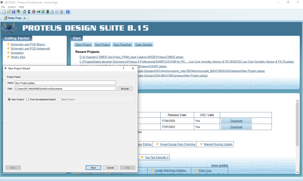
- Click on Pick Device
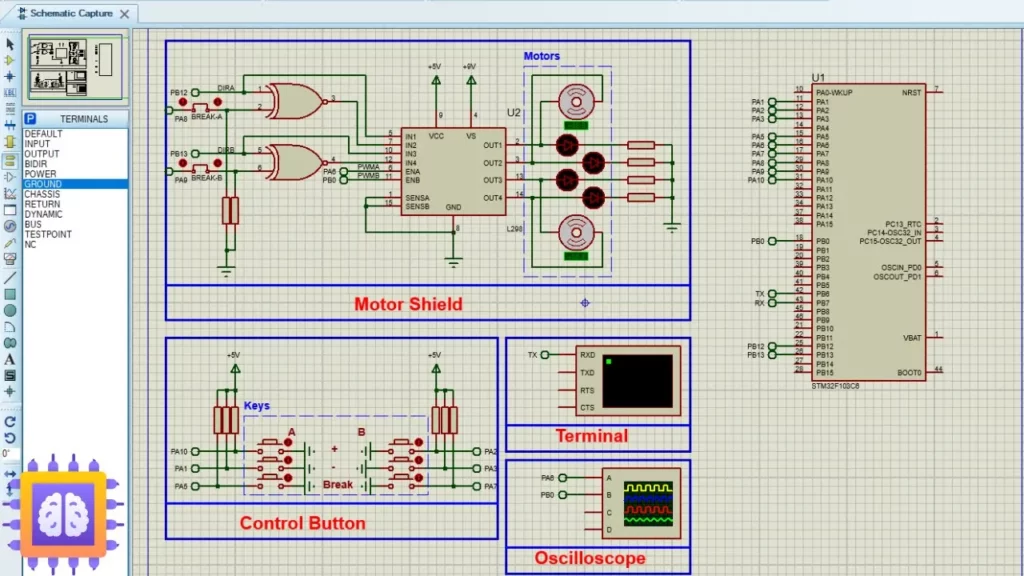
- Search for STM32F103C6 & RES & BUTTON & MOTOR-DC & L298 & 4077 & JUMPER & LED-YELLOW
- Click on Virtual Instruments Mode then choose (VIRTUAL TERMINAL & OSCILLOSCOPE)
- Click on Terminal Mode then choose (DEFAULT & POWER &GROUND)
- finally make the circuit below and start the simulation
That’s all!
If you have any questions or suggestions don’t hesitate to leave a comment below
1 comment
[…] if you’re interested in advanced configurations, consider exploring related projects like STM32 L298N Motor Driver: Dual H-Bridge for DC Motors. These projects expand on the principles of PWM and H-Bridge drivers, demonstrating their […]