Traffic Intersection Controller Using STM32

by Marwen Maghrebi

Things used in this project

Software apps and online services:

1- STMicroelectronics STM32CubeMX

2- STMicroelectronics STM32CubeIDE

3- Proteus 8

STM32 Microcontroller-Based Road Intersection Management System: Traffic Control and Efficiency Enhancement :

In this project, we will explore how build a road intersection management system using STM32 microcontroller The Road intersection management refers to the systematic approach and strategies employed to effectively control and regulate traffic flow at intersections where multiple roads intersect. It involves implementing various techniques, technologies, and traffic control measures to ensure safe and efficient movement of vehicles, pedestrians, and other road users. The primary objectives of road intersection management include optimizing traffic flow, minimizing congestion, reducing delays, enhancing safety, and improving overall transportation efficiency. This involves coordinating the movement of vehicles through the use of traffic signals, signage, lane markings, and other control devices.

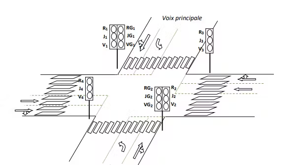
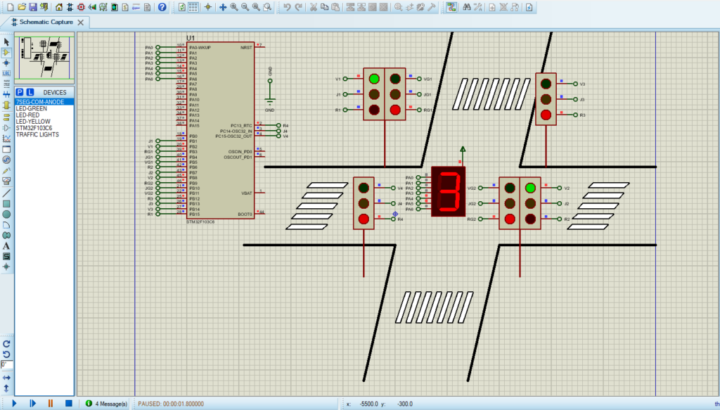
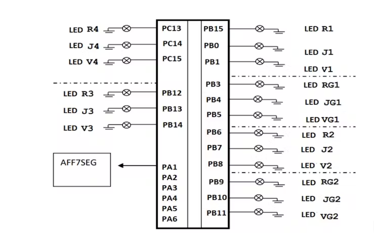
The road intersection, depicted in Figure 1, and the control interface is shown in Figure 2

Digital Road Intersection Management: STM32 Microcontroller Implementation:

This road intersection is controlled by four traffic lights. The designations of the lamps and buttons are as follows: Ri, Ji, and Vi: lamps used to control traffic in the straight and right directions. RGi, JGi, and VGi: lamps used to control traffic in the left direction. It should be noted that a lit Red lamp means a vehicle must stop. A lit Yellow lamp indicates that a vehicle should prepare (to stop or proceed with caution), and a lit Green lamp means a vehicle has the right of way. The Display 7SEG is used to display a cycle of 0..10 s for transitioning between stages. All inputs/outputs are digital. We will guide you through the design and development of a simplified model of this system based on partitioning into multiple functions.

STM32CubeMX Configuration:

Open CubeMX & Create New Project Choose The Target MCU STM32F103C6 & Double-Click Its Name

  • Go To The Clock Configuration & Set The System Clock To 8MHz

Pins Configuration for TRAFFIC LIGHTS:

  • Configure The GPIO Pins [PB15, PB0, PB1] and [PB3..PB5] as Output Pin for (the Full-size Traffic Light number 1) (R1, J1, V1) and (RG1, JG1, BG1);
  • Configure The GPIO Pins [PB6..PB8] and [PB9..PB11] as Output Pin for (the Full-size Traffic Light number 2) (R2, J2, V2) and (RG2, JG2, BG1);
  • Configure The GPIO Pins [PB12..PB14] and [PC13..PB15] as Output Pin for( the Mini Traffic Light number 1 and 2)(R3, J3, V3) and (R4, J4, V4).

Pins Configuration for the 7SEG display:

  • Configure The GPIO Pins [PA1..PA6] for the 7SEG display
  • Generate The Initialization Code & Open The Project In CubeIDE
  • Follow the flowchart of the main program

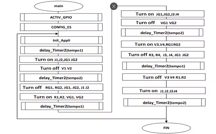
  • Write The Application Layer Code

STM32CubeIDE Configuration :

In file name :main.c

#include "main.h"

/* USER CODE BEGIN 0 */
void Decompt()
{
  uint8_t i,T[10]={0xc0, 0xf9, 0xa4, 0xb0, 0x99,0x92, 0x82, 0xf8, 0x80, 0x90};
  for (i=5;i>0;i--)
  {
    GPIOA->ODR= T[i-1];
    HAL_GPIO_TogglePin(GPIOB, GPIO_PIN_0);
    HAL_Delay(1000);
  }
}
/* USER CODE END 0 */

int main(void)
{
  HAL_Init();
  SystemClock_Config();
  MX_GPIO_Init();
 
  while (1)
  {

    //Turn ON V1,V2,RG1,RG2 and R3
    HAL_GPIO_WritePin(GPIOB,V1_Pin|RG1_Pin |V2_Pin|RG2_Pin|R3_Pin, GPIO_PIN_SET);
    HAL_GPIO_WritePin(GPIOC,R4_Pin, GPIO_PIN_SET);
    //Turn OFF J1,J2,J3 and J4
    HAL_GPIO_WritePin(GPIOB,J1_Pin|J2_Pin|J3_Pin, GPIO_PIN_RESET);
    HAL_GPIO_WritePin(GPIOC,J4_Pin, GPIO_PIN_RESET);

   //Decompt
    Decompt();

    //Turn ON J1,J2,JG1 et JG2
    HAL_GPIO_WritePin(GPIOB,J1_Pin|JG1_Pin|J2_Pin|JG2_Pin,GPIO_PIN_SET);
    //Turn OFF V1 ,V2,RG1,RG2
    HAL_GPIO_WritePin(GPIOB,V1_Pin|V2_Pin|RG1_Pin|RG2_Pin, GPIO_PIN_RESET);

    //delay
    HAL_Delay(1000);

    //Turn OFF J1, J2 ,JG1,JG2, RG1, RG2,
    HAL_GPIO_WritePin(GPIOB,J1_Pin|JG1_Pin|RG1_Pin|J2_Pin|JG2_Pin|RG2_Pin
    ,GPIO_PIN_RESET);
    //Turn ON R1,R2,VG1, VG2
    HAL_GPIO_WritePin(GPIOB, R1_Pin|R2_Pin|VG2_Pin|VG1_Pin, GPIO_PIN_SET);
    //Decompt
    Decompt();

    //allumer JG1,JG2,J3 and J4
    HAL_GPIO_WritePin(GPIOB,JG1_Pin|JG2_Pin|J3_Pin,GPIO_PIN_SET);
    HAL_GPIO_WritePin(GPIOC,J4_Pin,GPIO_PIN_SET);
    // Turn OFF VG1 ,VG2 and R3
    HAL_GPIO_WritePin(GPIOB,VG1_Pin|VG2_Pin|R3_Pin, GPIO_PIN_RESET);
    HAL_GPIO_WritePin(GPIOC,R4_Pin, GPIO_PIN_RESET);
    HAL_Delay(1000);

    //Turn ON V3,V4,RG1 et RG2
    HAL_GPIO_WritePin(GPIOB,V3_Pin|RG1_Pin|RG2_Pin,GPIO_PIN_SET);
    HAL_GPIO_WritePin(GPIOC,V4_Pin,GPIO_PIN_SET);
    //Turn OFF R3, R4, J3, J4, JG1 et JG2
    HAL_GPIO_WritePin(GPIOB,J3_Pin|R3_Pin|JG1_Pin|JG2_Pin,GPIO_PIN_RESET);
    HAL_GPIO_WritePin(GPIOC,J4_Pin|R4_Pin,GPIO_PIN_RESET);
    //Decompt
    Decompt();

    // Turn OFF V3,V4,R1 and R2
    HAL_GPIO_WritePin(GPIOB,V3_Pin|R1_Pin|R2_Pin,GPIO_PIN_RESET);
    HAL_GPIO_WritePin(GPIOC,V4_Pin,GPIO_PIN_RESET);
    //Turn ON J1,J2,J3 and J4
    HAL_GPIO_WritePin(GPIOB,J1_Pin|J2_Pin|J3_Pin,GPIO_PIN_SET);
    HAL_GPIO_WritePin(GPIOC,J4_Pin,GPIO_PIN_SET);
    HAL_Delay(1000);
  }}

Proteus Configuration :

  • Open Proteus & Create New Project and click next

  • Click on Pick Device
  • Search for STM32F103C6 & 7SEG-COM-ANODE & TRAFFIC LIGHT
  • Click on Terminal Mode then choose (DYNAMIC&POWER &GROUND)
  • finally make the circuit below and start the simulation

That’s all!

If you have any questions or suggestions don’t hesitate to leave a comment below

You Might Also Like

Leave a Comment


Are you sure want to unlock this post?
Unlock left : 0
Are you sure want to cancel subscription?
-
00:00
00:00
Update Required Flash plugin
-
00:00
00:00