In this article, we’ll explore how to interface the TM1637 4-Digit Display with an STM32 microcontroller for clear and efficient numeric display.
Things used in this project
Software apps and online services:
1- STMicroelectronics STM32CubeMX
2- STMicroelectronics STM32CubeIDE
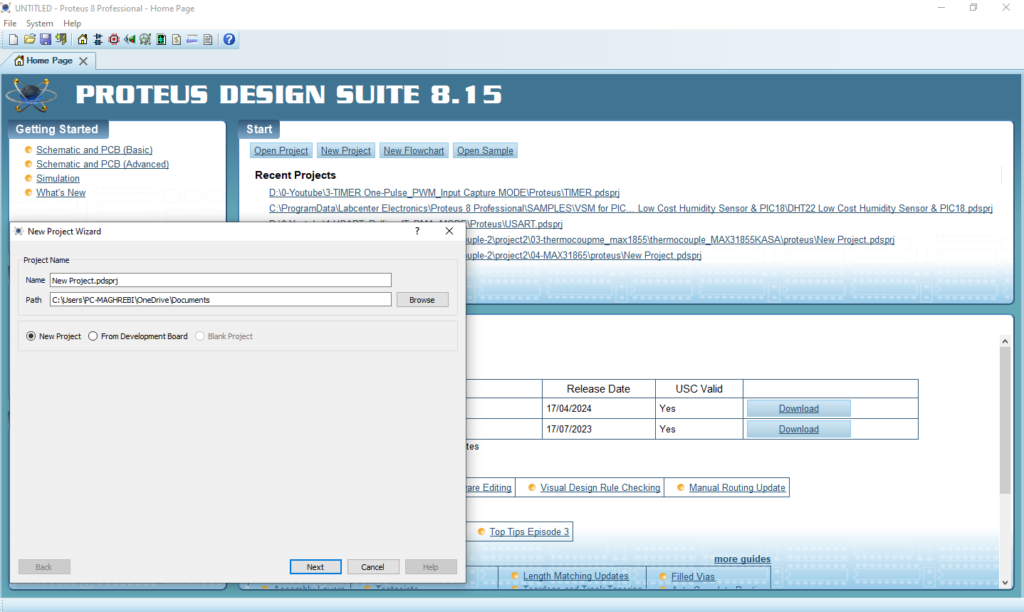
3- Proteus 8
Interfacing the TM1637 4-Digit 7-Segment Display with an STM32 Microcontroller
In this project, we will explore how to interface the TM1637 4-Digit 7-Segment Display with an STM32 microcontroller. This versatile display module is perfect for showcasing sensor data, time, and temperature readings.
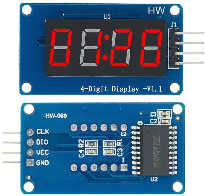
TM1637 Module Hardware Overview:
The TM1637 module is equipped with a 0.36-inch 4-digit 7-segment display and is driven by the TM1637 LED driver from Titan MicroElectronics. This configuration allows for control of all digits and the colon indicator using only two I/O pins, making it ideal for applications like clocks and temperature displays.
One of the key benefits of the TM1637 is its ability to autonomously manage display refreshing, allowing the microcontroller to dedicate resources to other tasks and improving overall efficiency. The module also features adjustable brightness and independent segment control for enhanced functionality.
Operating within a supply voltage range of 3.3V to 5V, the TM1637 communicates via a two-wire bus, simplifying connections to just two data pins, along with VCC and ground. Although it utilizes a proprietary data transfer protocol, Arduino libraries are readily available to facilitate communication.
Technical Specifications:
- Power Supply: 3.3V to 5V
- Communication Pins: 2 (CLK and DIO)
- Driver Chip: TM1637
- Display Sizes: 0.36-inch or 0.56-inch segments
- LED Color Options: White, red, blue, and green
- Display Features: Adjustable brightness, independent segment control
TM1637 Module Pinout:
The TM1637 module typically has the following pin configuration:
- VCC: Power supply pin
- GND: Ground pin
- CLK: Clock pin for communication
- DIO: Data input/output pin for communication
This project demonstrates how to interface an STM32 microcontroller with a TM1637 4-Digit Display by connecting the microcontroller’s GPIO pins to the display’s Clock and Data pins. The provided code facilitates display initialization, brightness control, and the ability to show numbers and characters, ensuring efficient communication. Overall, it showcases the TM1637 display’s functionality in embedded applications, emphasizing modular programming for better resource management.
STM32CubeMX Configuration:
- Open CubeMX & Create New Project Choose The Target MCU STM32F103C6 & Double-Click Its Name
- Go To The Clock Configuration & Set The System Clock To 72MHz
Configuration for the RTC Mode:
- In the Categories tab, (Activate Clock source calendar)
- In Parameter Settings Enbale auto Predivider Calculation & Asynchronous Predevider value
Configuration for the GPIO Mode:
- Configure The GPIO Pins [PB10 .. PB11] as Input Pins
- Generate The Initialization Code & Open The Project In CubeIDE
STM32CubeIDE Configuration:
- Write The Application Layer Code
- main.c
/* Includes ------------------------------------------------------------------*/
#include "main.h"

/* Private includes ----------------------------------------------------------*/
/* USER CODE BEGIN Includes */
#include "TM1637.h"
/* USER CODE END Includes */

/* Private define ------------------------------------------------------------*/
/* USER CODE BEGIN PD */

// Module connection pins (GPIO Pins)
#define CLK_PORT GPIOB
#define CLK_PIN GPIO_PIN_10
#define DIO_PORT GPIOB
#define DIO_PIN GPIO_PIN_11
 // The amount of time (in milliseconds) between tests
#define TEST_DELAY   250

const uint8_t SEG_DONE[] = {
        SEG_B | SEG_C | SEG_D | SEG_E | SEG_G,           // d
        SEG_A | SEG_B | SEG_C | SEG_D | SEG_E | SEG_F,   // O
        SEG_C | SEG_E | SEG_G,                           // n
        SEG_A | SEG_D | SEG_E | SEG_F | SEG_G            //e
};TM1637Display display;


int main(void)
{

  /* Reset of all peripherals, Initializes the Flash interface and the Systick. */
  HAL_Init();
  /* Configure the system clock */
  SystemClock_Config();
  /* Initialize all configured peripherals */
  MX_GPIO_Init();
  /* USER CODE BEGIN 2 */
  TM1637Display_init(&display, CLK_PORT, CLK_PIN, DIO_PORT, DIO_PIN, DEFAULT_BIT_DELAY);
  /* USER CODE END 2 */

  /* Infinite loop */
  /* USER CODE BEGIN WHILE */
  while (1)
  {
    /* USER CODE END WHILE */

    /* USER CODE BEGIN 3 */
      int k;
      uint8_t data[] = { 0xff, 0xff, 0xff, 0xff };
      uint8_t blank[] = { 0x00, 0x00, 0x00, 0x00 };

      TM1637Display_setBrightness(&display, 0x0f, true);

      // All segments onr t
      TM1637Display_setSegments(&display, data, 4, 0);
      HAL_Delay(TEST_DELAY);
       // Selectively set different digits
      data[0] = TM1637Display_encodeDigit(0);
      data[1] = TM1637Display_encodeDigit(1);
      data[2] = TM1637Display_encodeDigit(2);
      data[3] = TM1637Display_encodeDigit(3);
      TM1637Display_setSegments(&display, data, 4, 0);
      HAL_Delay(TEST_DELAY);

      TM1637Display_clear(&display);
      TM1637Display_setSegments(&display, data+2, 2, 2);
      HAL_Delay(TEST_DELAY);

      TM1637Display_clear(&display);
      TM1637Display_setSegments(&display, data+2, 2, 1);
      HAL_Delay(TEST_DELAY);

      TM1637Display_clear(&display);
      TM1637Display_setSegments(&display, data+1, 3, 1);
      HAL_Delay(TEST_DELAY);

      // Show decimal numbers with/without leading zeros
      TM1637Display_showNumberDec(&display, 0, false, 4, 0); // Expect: ___0
      HAL_Delay(TEST_DELAY);
      TM1637Display_showNumberDec(&display, 0, true, 4, 0);  // Expect: 0000
      HAL_Delay(TEST_DELAY);
      TM1637Display_showNumberDec(&display, 1, false, 4, 0); // Expect: ___1
      HAL_Delay(TEST_DELAY);
      TM1637Display_showNumberDec(&display, 1, true, 4, 0);  // Expect: 0001
      HAL_Delay(TEST_DELAY);
      TM1637Display_showNumberDec(&display, 301, false, 4, 0); // Expect: _301
      HAL_Delay(TEST_DELAY);
      TM1637Display_showNumberDec(&display, 301, true, 4, 0); // Expect: 0301
      HAL_Delay(TEST_DELAY);

      TM1637Display_clear(&display);
      TM1637Display_showNumberDec(&display, 14, false, 2, 1); // Expect: *14*
      HAL_Delay(TEST_DELAY);

      TM1637Display_clear(&display);
      TM1637Display_showNumberDec(&display, 4, true, 2, 2);  // Expect: __04
      HAL_Delay(TEST_DELAY);

      TM1637Display_showNumberDec(&display, -1, false, 4, 0);  // Expect: __-1
      HAL_Delay(TEST_DELAY);
      TM1637Display_showNumberDec(&display, -12, false, 4, 0);        // Expect: _-12
      HAL_Delay(TEST_DELAY);
      TM1637Display_showNumberDec(&display, -999, false, 4, 0);       // Expect: -999
      HAL_Delay(TEST_DELAY);

      TM1637Display_clear(&display);
      TM1637Display_showNumberDec(&display, -5, false, 3, 0); // Expect: *-5*
      HAL_Delay(TEST_DELAY);

      TM1637Display_showNumberHexEx(&display, 0xf1af, 0, false, 4, 0);        // Expect: f1Af
      HAL_Delay(TEST_DELAY);
      TM1637Display_showNumberHexEx(&display, 0x2c, 0, false, 4, 0);          // Expect: __2C
      HAL_Delay(TEST_DELAY);
      TM1637Display_showNumberHexEx(&display, 0xd1, 0, true, 4, 0); // Expect: 00d1
      HAL_Delay(TEST_DELAY);

      TM1637Display_clear(&display);
      TM1637Display_showNumberHexEx(&display, 0xd1, 0, true, 2, 0); // Expect: d1__
      HAL_Delay(TEST_DELAY);

      // Run through all the dots
      for(k=0; k <= 4; k++) {
          TM1637Display_showNumberDecEx(&display, 0, (0x80 >> k), true, 4, 0);
          HAL_Delay(TEST_DELAY);
      }

      // Brightness Test
      for(k = 0; k < 4; k++)
          data[k] = 0xff;
      for(k = 0; k < 7; k++) {
          TM1637Display_setBrightness(&display, k, true);
          TM1637Display_setSegments(&display, data, 4, 0);
          HAL_Delay(TEST_DELAY);
      }

      // On/Off test
      for(k = 0; k < 4; k++) {
          TM1637Display_setBrightness(&display, 7, false);  // Turn off
          TM1637Display_setSegments(&display, data, 4, 0);
          HAL_Delay(TEST_DELAY);
          TM1637Display_setBrightness(&display, 7, true); // Turn on
          TM1637Display_setSegments(&display, data, 4, 0);
          HAL_Delay(TEST_DELAY);
      }

      // Done!
      TM1637Display_setSegments(&display, SEG_DONE, 4, 0);
      while(1);
  }
  /* USER CODE END 3 */
}
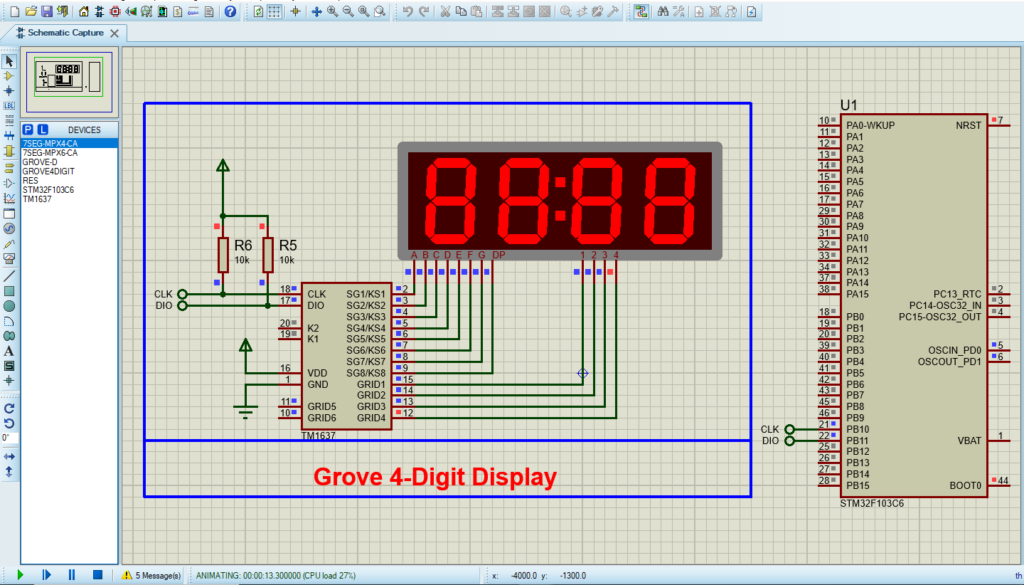
Proteus Configuration :
- Open Proteus & Create New Project and click next
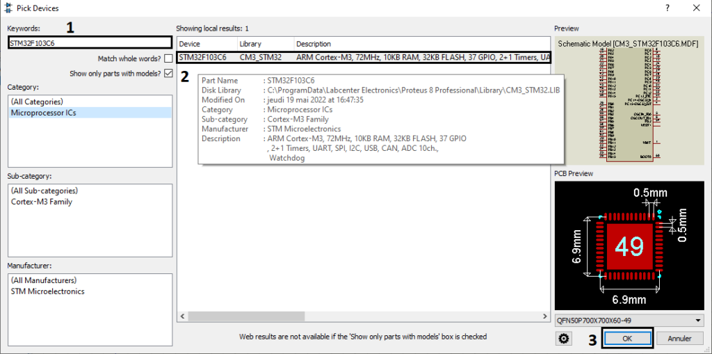
- Click on Pick Device
- Search for STM32F103C8 & ST7735R
- Click on Terminal Mode then choose (DYNAMIC & POWER &GROUND)
- finally make the circuit below and start the simulation