
In this article, we’ll explore how to interface the STM32 microcontroller with the DHT22 temperature and humidity sensor for precise environmental monitoring.

Things used in this project
Software apps and online services:
1- STMicroelectronics STM32CubeMX
2- STMicroelectronics STM32CubeIDE
3- Proteus 8
Interfacing STM32 with DHT22: A Step-by-Step Guide
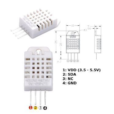
The DHT22, also known as the AM2302, serves as a popular digital temperature and humidity sensor. It provides calibrated digital output and finds extensive use in embedded systems for environmental monitoring. In this article, we will explore how to interface the DHT22 with an STM32 microcontroller. This guide builds on our previous integration of the DHT11 sensor, highlighting the differences and advantages of using the DHT22.
Overview of the DHT22 Sensor
The DHT22 sensor is a low-cost, reliable sensor that provides:
- Temperature measurement range: -40°C to 80°C (±0.5°C accuracy)
- Humidity measurement range: 0-100% RH (±2-5% accuracy)
Key Features:
- Digital Signal: DHT22 uses a single wire for data transmission, making it easy to interface with microcontrollers.
- Low Power Consumption: The sensor operates at 3.3V or 5V, making it compatible with Key Features: microcontrollers.
STM32 and DHT22 Communication
The communication between the STM32 microcontroller and the DHT22 sensor is based on a proprietary single-wire protocol. The sensor sends temperature and humidity data to the microcontroller in the form of a 40-bit data stream. These bits are split into humidity and temperature readings, as well as a checksum for data verification.
Data Frame Structure:
To read data from the DHT22, the STM32 microcontroller must first send a start signal, then listen for a response from the sensor. The microcontroller uses GPIO pins for the communication, and timing is crucial to properly handle the data frame.
- 16 bits: Humidity data
- 16 bits: Temperature data
- 8 bits: Checksum
STM32CubeMX Configuration:
- Open CubeMX & Create New Project Choose The Target MCU STM32F103C6 & Double-Click Its Name
- Go To The Clock Configuration & Set The System Clock To 16MHz
Configuration for the GPIO Mode:
- Configure The GPIO Pins PA0 as Output Pin
Configuration for the TIMER Mode:
- In the Categories tab, select the TIM1
- Enable Internal Clock
- In the Parameter settings tab, set the (Prescaler=15 & Counter Peroid 65535)
Configuration for the UART Mode:
- Enable USART1 Module (Asynchronous Mode)
- Set the USART1 communication parameters (baud rate = 115200, parity=NON, stop bits =1, and word length = 8bits)
- Generate The Initialization Code & Open The Project In CubeIDE
STM32CubeIDE Configuration:
Includes and Defines
In the initial section, the code includes standard libraries for string manipulation and formatted output. The string.h library is used for handling strings, while stdio.h allows for formatted data output. Additionally, the code defines constants to specify the GPIO pin and port connected to the DHT22 sensor. It also declares several variables to hold messages and data received from the sensor, including the temperature and humidity bytes, checksum, and a timeout variable.
/* USER CODE BEGIN Includes */
#include <string.h>
#include <stdio.h>
/* USER CODE END Includes */

/* USER CODE BEGIN PD */
#define DHT22_Pin GPIO_PIN_0
#define DHT22_GPIO_Port GPIOA
/* USER CODE END PD */

/* USER CODE BEGIN PV */
char message1[16];
char message2[16];
uint8_t TOUT = 0, CheckSum, i;
uint8_t T_Byte1, T_Byte2, RH_Byte1, RH_Byte2;
/* USER CODE END PV */
Start Signal Function
The start_signal function is crucial for initiating communication with the DHT22 sensor. It configures the specified GPIO pin as an output to send a start signal. The pin is set low for 18 milliseconds, signaling the sensor to prepare for data transmission, before being set high for a brief duration. This transition allows the sensor to respond, and the pin is then reconfigured as an input to read the incoming data. This sequence ensures that the sensor is ready to send data when called upon.
void start_signal(void) {
    GPIO_InitTypeDef GPIO_InitStruct = {0};
    GPIO_InitStruct.Pin = DHT22_Pin;
    GPIO_InitStruct.Mode = GPIO_MODE_OUTPUT_PP;
    GPIO_InitStruct.Pull = GPIO_NOPULL;
    GPIO_InitStruct.Speed = GPIO_SPEED_FREQ_LOW;
    HAL_GPIO_Init(DHT22_GPIO_Port, &GPIO_InitStruct);

    HAL_GPIO_WritePin(DHT22_GPIO_Port, DHT22_Pin, GPIO_PIN_RESET);
    HAL_Delay(18);
    HAL_GPIO_WritePin(DHT22_GPIO_Port, DHT22_Pin, GPIO_PIN_SET);
    delay_us(30); // Wait 20-40μs

    GPIO_InitStruct.Mode = GPIO_MODE_INPUT;
    HAL_GPIO_Init(DHT22_GPIO_Port, &GPIO_InitStruct);
}
Check Response Function
The check_response function verifies whether the DHT22 sensor is responding after the start signal is sent. It utilizes a timer to enforce a timeout of 100 timer ticks while checking for the low signal from the sensor, which indicates a response. If the sensor responds correctly, the function will return 1, confirming successful communication; if not, it returns 0, indicating that the expected response was not received within the allotted time.
uint8_t check_response(void) {
    TOUT = 0;
    __HAL_TIM_SET_COUNTER(&htim1, 0);
    while (!HAL_GPIO_ReadPin(DHT22_GPIO_Port, DHT22_Pin) && (__HAL_TIM_GET_COUNTER(&htim1) < 100)) {};
    if (__HAL_TIM_GET_COUNTER(&htim1) >= 100)
        return 0;

    __HAL_TIM_SET_COUNTER(&htim1, 0);
    while (HAL_GPIO_ReadPin(DHT22_GPIO_Port, DHT22_Pin) && (__HAL_TIM_GET_COUNTER(&htim1) < 100)) {};
    if (__HAL_TIM_GET_COUNTER(&htim1) >= 100)
        return 0;

    return 1;
}
Read Byte Function
In the read_byte function, the code reads a byte of data from the DHT22 sensor by detecting the duration of high signals corresponding to individual bits. The function waits for a low signal, marking the start of a bit, and measures how long the pin remains high. If the high duration exceeds 40 microseconds, the corresponding bit is recorded as 1; otherwise, it is recorded as 0. This process is repeated eight times to assemble a complete byte, which is then returned.
uint8_t read_byte(void) {
    uint8_t num = 0;
    for (i = 0; i < 8; i++) {
        while (!HAL_GPIO_ReadPin(DHT22_GPIO_Port, DHT22_Pin)) {};
        __HAL_TIM_SET_COUNTER(&htim1, 0);
        while (HAL_GPIO_ReadPin(DHT22_GPIO_Port, DHT22_Pin)) {};
        if (__HAL_TIM_GET_COUNTER(&htim1) > 40) // 40μs threshold
            num |= (1 << (7 - i));
    }
    return num;
}
Send UART Function
The send_uart function is responsible for transmitting strings over UART. It takes a pointer to a string as an argument and uses the HAL_UART_Transmit function to send the string through the specified UART interface (huart1). The string is converted into a byte array for transmission, allowing for easy communication of messages, such as sensor readings or error notifications.
void send_uart(char *string) {
    HAL_UART_Transmit(&huart1, (uint8_t*)string, strlen(string), HAL_MAX_DELAY);
}
Main Function
In the main function, several variables for voltage, temperature, and message formatting are initialized. The function begins by calling HAL_Init() to reset peripherals and set up the system clock, followed by initializing the GPIO, USART, and timer peripherals. Once the initialization is complete, a message is sent over UART. The infinite loop starts with a delay of one second, after which it sends a start signal to the DHT22 sensor. If the sensor responds, it reads the humidity and temperature data, checking the validity through a checksum. If the data is valid, the readings are formatted and sent over UART; if not, an error message is displayed, indicating a checksum failure. This structure allows for continuous monitoring of temperature and humidity in a reliable manner
int main(void) {
    /* USER CODE BEGIN 1 */
    float Voltage_mV = 0;
    float Temperature_C = 0;
    float Temperature_F = 0;
    char msg[50];
    /* USER CODE END 1 */

    HAL_Init();
    SystemClock_Config();
    MX_GPIO_Init();
    MX_USART1_UART_Init();
    MX_TIM1_Init();

    /* USER CODE BEGIN 2 */
    HAL_TIM_Base_Start(&htim1);
    send_uart("Initialization complete\n\r");
    /* USER CODE END 2 */

    /* USER CODE BEGIN WHILE */
    while (1) {
        HAL_Delay(1000); // Delay for 1 second
        start_signal(); // Send start signal to DHT22

        uint8_t check = check_response();
        if (!check) {
            send_uart("No response from the sensor\r\n");
        } else {
            // Read bytes from DHT22
            RH_Byte1 = read_byte();
            RH_Byte2 = read_byte();
            T_Byte1 = read_byte();
            T_Byte2 = read_byte();
            CheckSum = read_byte();

            // Combine humidity and temperature bytes
            uint16_t rh = (RH_Byte1 << 8) | RH_Byte2;
            uint16_t temp = (T_Byte1 << 8) | T_Byte2;
            uint8_t sign = 0;

            // Check if temperature is negative
            if (temp > 0x8000) {
                temp &= 0x7FFF; // Clear the sign bit
                sign = 1; // Indicate negative temperature
            }

            char rh_buf[5], temp_buf[5];
            sprintf(rh_buf, "%03u", rh);
            sprintf(temp_buf, "%03u", temp);

            // Check checksum
            if (CheckSum == ((RH_Byte1 + RH_Byte2 + T_Byte1 + T_Byte2) & 0xFF)) {
                sprintf(msg, "RH = %03u.%1u %% ", rh / 10, rh % 10);
                send_uart(msg);
                sprintf(msg, "Temp = %c%03u.%1u C \r\n", sign ? '-' : ' ', temp / 10, temp % 10);
                send_uart(msg);
            } else {
                send_uart("Checksum Error! Trying Again ...\r\n");
            }
        }
    }
}
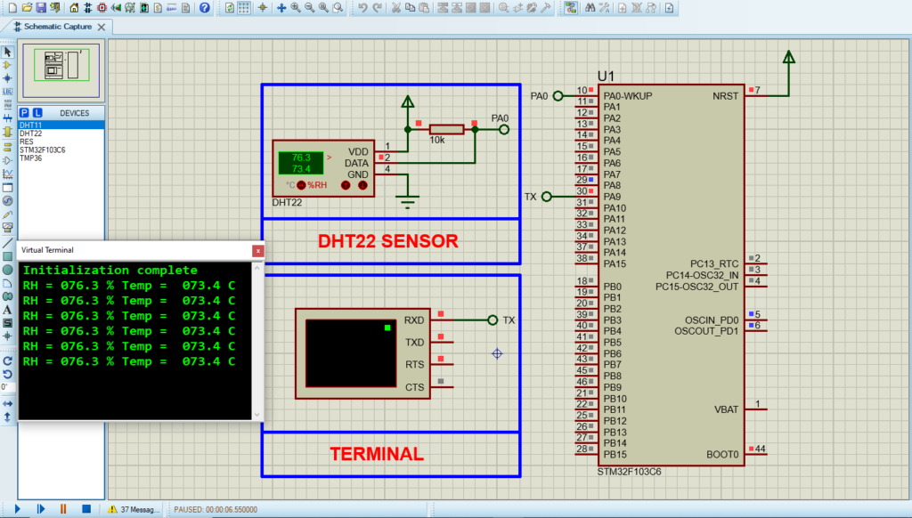
Proteus Configuration :
- Open Proteus & Create New Project and click next

- Click on Pick Device
- Search for STM32F103C6 & RES & DHT22
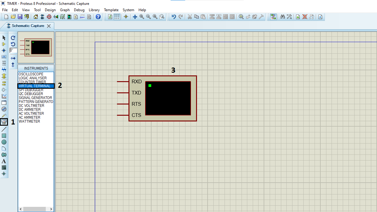
- Click on Virtual Instruments Mode then choose Terminal
- Click on Terminal Mode then choose (DEFAULT & POWER &GROUND)
- finally make the circuit below and start the simulation
That’s all!
If you have any questions or suggestions don’t hesitate to leave a comment below.