STM32 UART Communication Modes Exploration: Polling,Interrupt,DMA

by Marwen Maghrebi

In this article, we explore STM32 UART communication and its three key modes: Polling, Interrupt, and DMA. Understanding these modes is essential for optimizing data exchange in embedded systems and improving performance in STM32 projects

STM32 UART communication modes: Polling, Interrupt, DMA setup

Things used in this project

Software apps and online services

1- STMicroelectronics STM32CubeMX

2- STMicroelectronics STM32CubeIDE

3- Proteus 8

Virtual Terminal Implementation for UART Communication on STM32:

In this project, the focus is on exploring different modes of USART communication on an STM32 microcontroller. Specifically, the project will cover three modes: polling, interrupt, and DMA

Polling Mode Implementation :

In polling mode, the microcontroller continuously checks for incoming data from the UART communication interface and processes it. This mode is relatively simple but can consume significant processing power.

Interrupt Mode Configuration and Implementation:

In interrupt mode, the microcontroller receives a signal from the STM32 UART communication system when data is ready to be processed. This mode is more efficient, as the microcontroller can perform other tasks while waiting for data to arrive.

DMA Mode Setup and Implementation for Efficient:

In DMA (Direct Memory Access) mode, the microcontroller can transfer data between the UART and memory without CPU intervention. This mode reduces processing overhead and enhances the performance of the STM32 UART communication system.

The project will cover the configuration and implementation of each mode on the STM32 microcontroller using the HAL (Hardware Abstraction Layer) library. It will also include practical examples of using each mode for data transfer between STM32 UART communication and Virtual Terminal.

STM32CubeMX Configuration:

  • Open CubeMX & Create New Project Choose The Target MCU STM32F103C6 & Double-Click Its Name
  • Go To The Clock Configuration & Set The System Clock To 16MHz
  • Enable USART1 and USART2 Module (Asynchronous Mode)
  • Set the USART1 and USART2 communication parameters (baud rate = 9600, parity=NON, stop bits =1, and word length =8bits)
  • In the NVIC settings tab, enable the interrupt for the USART1 peripheral
  • In the DMA settings tab, enable the DMA for the USART2 peripheral
  • Configure The GPIO Pins PB0, and PB1 as Input Pin
  • Configure The GPIO Pins PB14, and PB15 as Output Pin
  • Generate The Initialization Code & Open The Project In CubeIDE
  • Write The Application Layer Code

STM32CubeIDE Configuration:

In file name :main.c

#include "main.h"

/* USER CODE BEGIN PV */
char str0[50] = "USART Polling Mode \n\r";
char str1[50] = "USART Interrupt Mode \n\r";
char str2[50] = "USART DMA Mode \n\r";
/* USER CODE END PV */

/* USER CODE BEGIN 0 */
void HAL_UART_TxCpltCallback(UART_HandleTypeDef *huart)
{
 if (huart == &huart1)
 {
   HAL_GPIO_WritePin(GPIOB, GPIO_PIN_14, 0);
   HAL_GPIO_WritePin(GPIOB, GPIO_PIN_15, 1);
 }
 if (huart == &huart2)  
  {
    HAL_GPIO_WritePin(GPIOB, GPIO_PIN_14, 1);
    HAL_GPIO_WritePin(GPIOB, GPIO_PIN_15, 0);
  }
}
/* USER CODE END 0 */

int main(void)
{
  HAL_Init();
  SystemClock_Config();
  MX_GPIO_Init();
  MX_DMA_Init();
  MX_USART1_UART_Init();
  MX_USART2_UART_Init();

  while (1)
  {
    if(HAL_GPIO_ReadPin(GPIOB, GPIO_PIN_0)==GPIO_PIN_SET)         //Polling Mode
        {
      HAL_UART_Transmit(&huart1, (uint8_t*)str0, sizeof(str0),100);
      HAL_Delay(200);
        }
    else if(HAL_GPIO_ReadPin(GPIOB, GPIO_PIN_1)==GPIO_PIN_SET)       //Interrupt Mode
       {
      HAL_UART_Transmit_IT(&huart1,(uint8_t*)str1, sizeof(str1));
      HAL_Delay(200);
       }
    else if(HAL_GPIO_ReadPin(GPIOB, GPIO_PIN_2)==GPIO_PIN_SET)       //DMA Mode
       {
      HAL_UART_Transmit_DMA(&huart2,(uint8_t*)str2, sizeof(str2));
      HAL_Delay(200);
       }
    else
    {
      HAL_UART_Abort(&huart1);
      HAL_UART_Abort(&huart2);
    }
  }
  /* USER CODE END 3 */
}

Proteus Configuration :

  • Open Proteus & Create New Project and click next

  • Click on Pick Device
  • Search for STM32F103C6 & SW-SPDT(switch) & LED_RED BLUE and YELLOW
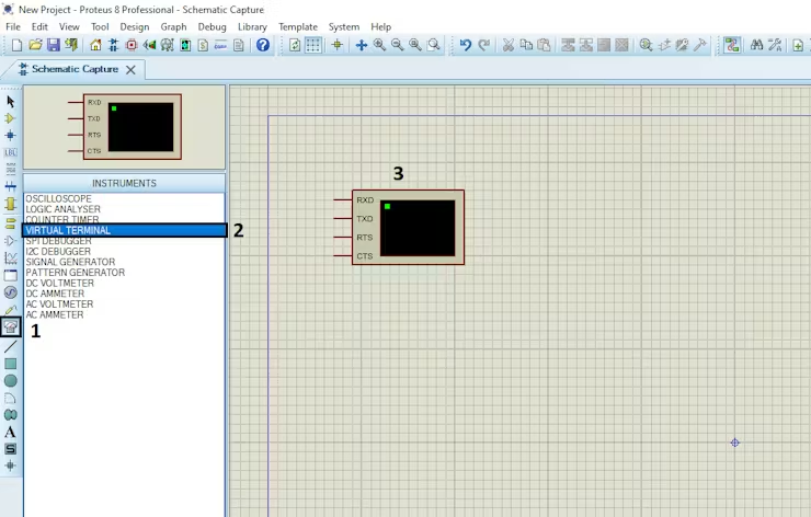
  • Click on Virtual Instruments Mode then choose VIRTUAL TERMINAL

  • Click on Terminal Mode then choose (DEFAULT & POWER &GROUND)
  • finally make the circuit below and start the simulation

That’s all!

If you have any questions or suggestions don’t hesitate to leave a comment below

You Might Also Like

2 comments

Leave a Comment


Are you sure want to unlock this post?
Unlock left : 0
Are you sure want to cancel subscription?
-
00:00
00:00
Update Required Flash plugin
-
00:00
00:00