
Table of Contents

In this project, we explore the integration of the TMP36 temperature sensor with ùùmicrocontrollers, emphasizing low-level interfacing techniques to maximize control and efficiency. By bypassing high-level libraries, we gain a deeper understanding of the sensor’s operation and enhance our ability to optimize performance for specific applications.
TMP36 Pinout and Basic Operation :
The TMP36 sensor is a low-voltage, precision centigrade temperature sensor. It operates at a supply voltage range of 2.7V to 5.5V, making it ideal for integration with STM32 microcontrollers. The sensor has three pins:
- VCC: Connects to the power supply (2.7V to 5.5V)
- GND: Ground
- VOUT: Analog voltage output that varies with temperature
The TMP36 provides an analog voltage output that is linearly proportional to the temperature in degrees Celsius. Specifically, the output voltage (in millivolts) can be calculated as:
Technical Specifications of TMP36 :
- Operates from 2.7V to 5.5V
- Linear +10 mV/°C scale factor
- ±0.5°C linearity
- ±2°C accuracy over temperature (typical)
- Rated for full -40°C to 125°C range, operates up to +150°C
- Less than 50 μA current drain
- VOUT range: 0.1V at -40°C to 1.75V at 125°C
- VOUT at room temperature (25°C) is 0.75V
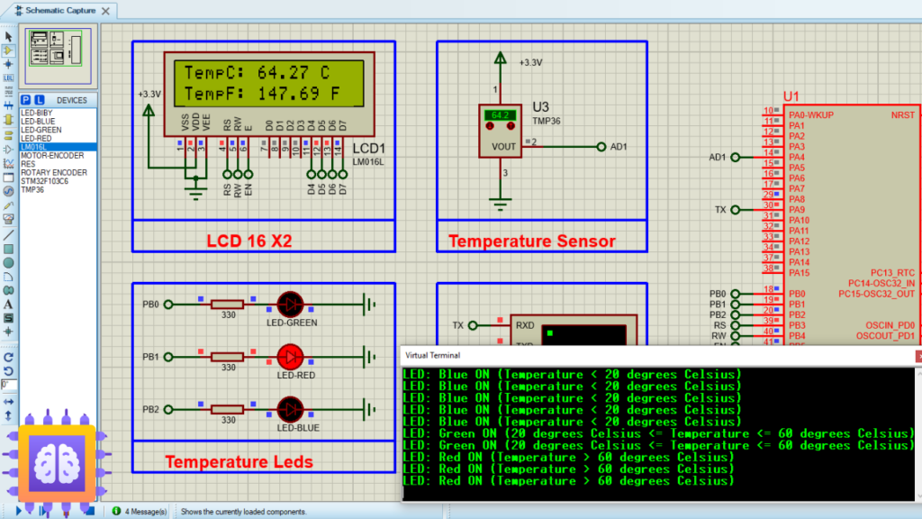
To kickstart this project, we’ll configure the STM32 microcontroller to interface with the TMP36 temperature sensor and display temperature readings on an LCD screen. Specifically, we’ll use the HAL library to initialize the ADC for reading the sensor output, and UART for debugging and monitoring purposes. We will also configure GPIO pins to control LEDs based on temperature thresholds. This setup will allow us to efficiently monitor temperature and provide visual alerts, thereby optimizing system responsiveness and user interaction.0
Proteus Configuration :
- Open Proteus & Create New Project and click next

- Click on Pick Device
- Search for STM32F103C6 & LED-RED & LED-GREEN , LED_BLUE, TMP36
- Click on Virtual Instruments Mode then choose Terminal
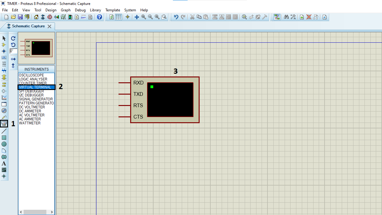
- Click on Terminal Mode then choose (DEFAULT & POWER &GROUND)
10 comments
very good! thanks so much
Thank you! I’m glad you found it helpful! 😊
how much baude rate did you put in Virtual terminal
I used a baud rate of 115200 in the virtual terminal
Very good, but in Proteus 8, when I click run, I get this message: “No power supply specified for net VDDA in Power Rail Configuration. No power supply specified for net VSSA in Power Rail Configuration.”
1-First, navigate to the power rail configuration:
-Click on “Design” in the top menu
-Select “Configure Power Rails…”
2-For VDDA configuration:
-In the Power Rail Configuration window, select “VCC/VDD” from the Name dropdown
-Set Voltage to 3.3V
-Make sure Class is set to “POWER”
-Use the “Add->” button to connect VDDA to VDD
You should see both VDD and VDDA listed in the “Nets connected to VCC/VDD” box
3-For VSSA configuration:
-Switch to “GND” in the Name dropdown
-Voltage should be 0V
-Class should remain as “POWER”
-Use the “Add->” button to connect VSSA to GND
You should see GND, VSS, and VSSA listed in the “Nets connected to GND” box
Make sure “Use default power rail connections?” is checked at the bottom of the window
Click “OK” to apply the changes
After completing these steps, the error messages about VDDA and VSSA should be resolved, and your simulation should run properly. The power rails are now properly configured with VDDA connected to the 3.3V supply and VSSA connected to ground.
Bro, Can you add me on teams to talk about project,i need this project for school,but can not run it,
I don’t have Teams right now, but you can contact me via email if you want : ” [email protected] ” . Let me know what specific issues you’re having with the project, and I’ll try my best to help you resolve them.
Marwen, could you check the email I sent you if you have time?
Inas, I apologize for the late reply. I haven’t received any email from you. Could you please try contacting me at [email protected] ? Thanks!