
In this article, we will demonstrate how to control a stepper motor using the STM32 microcontroller. Utilizing the ULN2003 driver, you’ll achieve precise and efficient motion for various applications.
Things used in this project
Software apps and online services:
1- STMicroelectronics STM32CubeMX
2- STMicroelectronics STM32CubeIDE
3- Proteus 8
Driving a Stepper Motor with the ULN2003 Motor Driver and STM32
Stepper motors are commonly used in precise control applications, but driving them directly from a microcontroller, such as an STM32, can be challenging due to their high current requirements. The ULN2003 motor driver IC offers an efficient solution for STM32 Stepper Motor Control. This article provides an overview of how the ULN2003 works, its pinout, and how to interface it with a stepper motor using the STM32 microcontroller.
What is the ULN2003?
The ULN2003 is a high-voltage, high-current Darlington transistor array IC, ideal for driving high-current loads like motors, relays, or high-power LEDs. It becomes particularly useful when the current or voltage required to drive the load exceeds the capabilities of the microcontroller’s GPIO pins. For instance, an STM32 I/O pin typically provides a maximum of 20–40 mA, while a motor might require 300 mA or more. The ULN2003 steps in to bridge this gap, enabling reliable STM32 Stepper Motor Control.
Key Features of the ULN2003?
- Seven Darlington pairs: Each pair can handle 50V and up to 500mA.
- Input triggered by logic levels: You can control the IC using a 5V logic signal.
- Handles multiple loads: With seven pairs of inputs and outputs, you can control several loads simultaneously.
- Expandable current handling: You can combine multiple outputs to drive larger loads up to 3.5A.
Pin-compatible: Available in standard 16-pin DIP, TSSOP, and SOIC packages.
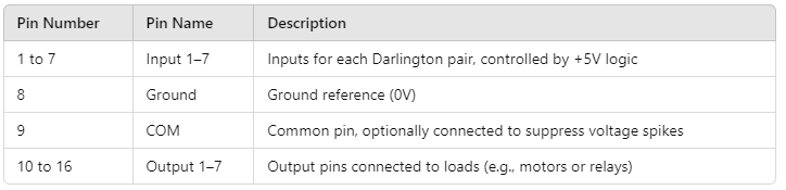
Pinout Configuration
The ULN2003 has 16 pins, with the relevant ones for controlling a stepper motor being the input and output pins. Here’s a basic pinout configuration for the ULN2003 driver when interfaced with a stepper motor like the 28BYJ-48:
How the ULN2003 Works
In the context of STM32 Stepper Motor Control, each input pin of the ULN2003 controls one of the Darlington pairs within the driver. When an input pin receives a high signal (typically +5V), its corresponding output pin connects to ground. This connection completes the circuit for the load attached to that output pin, allowing current to flow from the power supply through the load and into the ULN2003, which grounds the load.
Interfacing the 28BYJ-48 Stepper Motor with the ULN2003
The 28BYJ-48 is a unipolar stepper motor with 4 coils that requires four control signals to rotate in steps. The ULN2003 driver is an ideal interface for this motor, allowing it to handle the higher current requirements. Here’s a breakdown of how the STM32 controls the motor via the ULN2003:
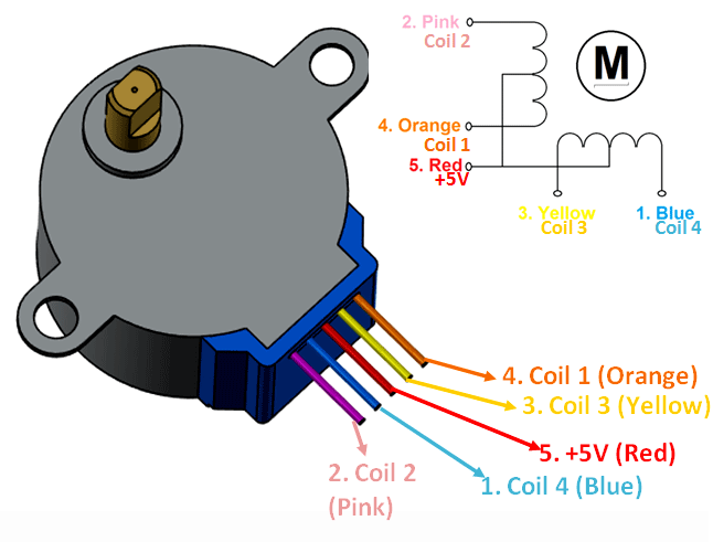
Pin Configuration
The 28BYJ-48 stepper motor has five wires, with the key connections being as follows: A corresponds to Coil 1, B to Coil 2, C to Coil 3, D to Coil 4, and the Common wire, which is typically connected to +5V, serves as the center tap.
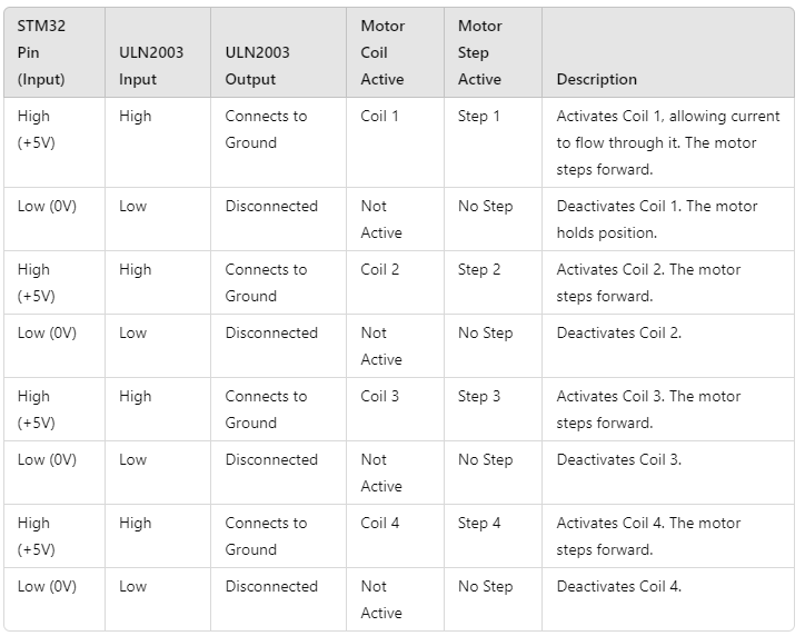
Control Logic
To rotate the 28BYJ-48 motor, the STM32 sends control signals in a specific sequence. Here’s a table displaying the pin states required to control the stepper motor:
To kickstart this project, we will configure the STM32 microcontroller to control a stepper motor through the ULN2003 motor driver IC. We will utilize the HAL library to manage GPIO pins for user input, allowing us to adjust the motor’s direction using simple button presses. The program defines a stepping sequence to precisely control the motor’s rotation, incorporating delay mechanisms for speed regulation. This setup provides a straightforward and efficient way to drive a stepper motor, making it suitable for various automation and robotics applications.
STM32CubeMX Configuration:
- Open CubeMX & Create New Project Choose The Target MCU STM32F103C6 & Double-Click Its Name
- Go To The Clock Configuration & Set The System Clock To 16MHz
Configuration for the GPIO Mode:
- Configure The GPIO Pins [PA1,PA2] as Output Pins (FOR,REV)
- Configure The GPIO Pins [PB0..PB3] as Output Pins
- Generate The Initialization Code & Open The Project In CubeIDE
STM32CubeIDE Configuration :
- Write The Application Layer Code
/* Includes ------------------------------------------------------------------*/
#include "main.h"

/* Private define ------------------------------------------------------------*/
/* USER CODE BEGIN PD */
const uint8_t turn[] = {0x02, 0x06, 0x04, 0x0C, 0x08, 0x09, 0x01, 0x03};
uint8_t i = 0;
uint32_t adc_value = 0;
uint32_t delay ;
/* USER CODE END PD */

/* Private variables ---------------------------------------------------------*/
ADC_HandleTypeDef hadc1;
DMA_HandleTypeDef hdma_adc1;

/* Private function prototypes -----------------------------------------------*/
void SystemClock_Config(void);
static void MX_GPIO_Init(void);
static void MX_DMA_Init(void);
static void MX_ADC1_Init(void);
/**
  * @brief  The application entry point.
  * @retval int
  */
int main(void)
{
  /* Reset of all peripherals, Initializes the Flash interface and the Systick. */
  HAL_Init();
  /* Configure the system clock */
  SystemClock_Config();
  /* Initialize all configured peripherals */
  MX_GPIO_Init();
  MX_DMA_Init();
  MX_ADC1_Init();

  /* Infinite loop */
  /* USER CODE BEGIN WHILE */
  while (1)
  {
    /* USER CODE END WHILE */

    /* USER CODE BEGIN 3 */
      if (HAL_GPIO_ReadPin(GPIOA, GPIO_PIN_1) == GPIO_PIN_RESET)
          {
            i = (i < 7) ? i + 1 : 0;
            GPIOB->ODR = turn[i];
            HAL_Delay(100);
          }
      else if (HAL_GPIO_ReadPin(GPIOA, GPIO_PIN_2) == GPIO_PIN_RESET)
          {
            i = (i > 0) ? i - 1 : 7;
            GPIOB->ODR = turn[i];
            HAL_Delay(100);
          }

  }
  /* USER CODE END 3 */
}
Proteus Configuration :
- Open Proteus & Create New Project and click next
- Click on Pick Device
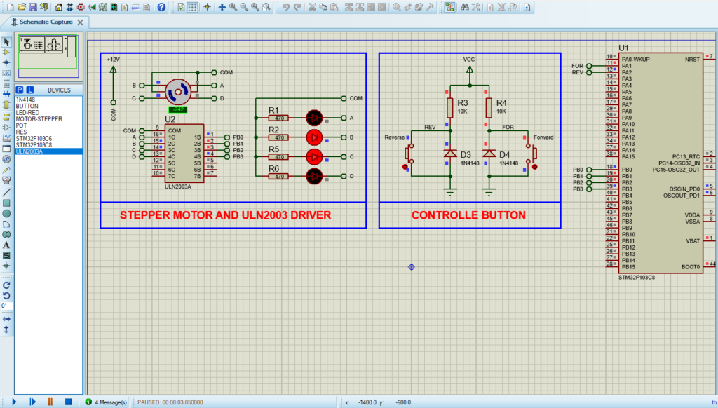
- Search for STM32F103C6 & LED-RED & RES , Button , 1N4148 , ULN2003A , MOTOR-STEPPER
- Click on Terminal Mode then choose (DEFAULT & POWER &GROUND)
- finally make the circuit below and start the simulation
That’s all!
If you have any questions or suggestions don’t hesitate to leave a comment below.
1 comment
[…] In this project, we will explore how to interface the PIC16F877A microcontroller with the ULN2003 driver to control a stepper motor, providing precise motion control ideal for robotics and automation applications. For additional insights, check out a related project: “Driving a Stepper Motor with the ULN2003 Motor Driver and STM32.” […]