
In this article, we explore SPI communication methods for STM32 microcontrollers, focusing on SPI Polling, Interrupt, and DMA to understand their advantages and applications
Things used in this project
Software apps and online services:
1- STMicroelectronics STM32CubeMX
2- STMicroelectronics STM32CubeIDE
3- Proteus 8
Optimizing SPI Communication Efficiency Between STM32 Microcontrollers: Polling, Interrupt, and DMA Modes Investigation :
This project aims to investigate the efficient implementation of SPI communication between two STM32 microcontrollers using various modes of communication, namely polling, interrupt, and DMA. The SPI protocol is widely used for communication between microcontrollers, and optimizing its implementation can greatly improve the overall performance of a system.
SPI is used in blocking mode (polling):
In polling mode, the microcontroller continuously checks the SPI status flags to determine if data has been received or if the transmit buffer is empty.
SPI is used in blocking mode (interrupt):
In interrupt mode, the microcontroller generates an interrupt when the SPI status flags indicate that data has been received or when the transmit buffer is empty. The interrupt service routine (ISR) processes the received data and fills the transmit buffer.
SPI is used in blocking mode (DMA):
In DMA mode, the microcontroller transfers data between the SPI and memory without CPU intervention. The DMA controller manages the data transfer, freeing the CPU to perform other tasks.
The project will cover the implementation of each mode of communication using the SPI interface on the STM32 microcontroller and evaluate its performance in transferring data between the two STM32 boards (Master & Slave) using Proteus simulation. By simulating the system in Proteus, we can explore different scenarios and observe the behavior of the system under different conditions.
STM32CubeMX Configuration:
Master board Configuration:
- Open CubeMX & Create New Project Choose The Target MCU STM32F103C6 & Double-Click Its Name
- Go To The Clock Configuration & Set The System Clock To 8MHz
- Configure The GPIO Pins PB13, PB14 and PB15 as Input Pin
- Configure The GPIO Pins PB12and PA4 as Output Pin
- In the Categories tab, select the SPI1 & Full-Duplex Master
- Generate The Initialization Code & Open The Project In CubeIDE
STM32CubeIDE Configuration :
- Write The Application Layer Code
- main.c
#include "main.h"

char TxBuff1[20]="MASTER SEND ONE";
char TxBuff2[20]="MASTER SEND TWO";
uint8_t txBuffer = 0;

int main(void)
{
  HAL_Init();
  SystemClock_Config();
  MX_GPIO_Init();
  MX_SPI1_Init();
while (1)
  {
if((HAL_GPIO_ReadPin(GPIOB, GPIO_PIN_13)|HAL_GPIO_ReadPin(GPIOB, GPIO_PIN_14)|HAL_GPIO_ReadPin(GPIOB, GPIO_PIN_15))==GPIO_PIN_RESET)
  {
  HAL_GPIO_TogglePin(GPIOB, GPIO_PIN_12);
  HAL_Delay(100);
  //send For Polling Mode receive
  if(HAL_GPIO_ReadPin(GPIOB, GPIO_PIN_13)==GPIO_PIN_SET)
  {
  HAL_GPIO_WritePin(GPIOA, GPIO_PIN_4, GPIO_PIN_RESET);
  HAL_SPI_Transmit(&hspi1, (uint8_t*)TxBuff1, sizeof(TxBuff1),5000);
  HAL_GPIO_WritePin(GPIOA, GPIO_PIN_4, GPIO_PIN_SET);
  while(HAL_GPIO_ReadPin(GPIOB, GPIO_PIN_13)==GPIO_PIN_RESET);
  }
  //send For IT Mode receive
  if(HAL_GPIO_ReadPin(GPIOB, GPIO_PIN_14)==GPIO_PIN_SET)
  {
   txBuffer=txBuffer == 0?1:0;
   HAL_GPIO_WritePin(GPIOA, GPIO_PIN_4, GPIO_PIN_RESET);
   HAL_SPI_Transmit(&hspi1,&txBuffer, sizeof(txBuffer),5000);
   HAL_GPIO_WritePin(GPIOA, GPIO_PIN_4, GPIO_PIN_SET);
   while(HAL_GPIO_ReadPin(GPIOB, GPIO_PIN_14)==GPIO_PIN_RESET);
  }
  //send For IT Mode receive
  if(HAL_GPIO_ReadPin(GPIOB, GPIO_PIN_15)==GPIO_PIN_SET)
  {
   HAL_GPIO_WritePin(GPIOA, GPIO_PIN_4, GPIO_PIN_RESET);
   HAL_SPI_Transmit(&hspi1,(uint8_t*)TxBuff2, sizeof(TxBuff2),5000);
   HAL_GPIO_WritePin(GPIOA, GPIO_PIN_4, GPIO_PIN_SET);
   while(HAL_GPIO_ReadPin(GPIOB, GPIO_PIN_15)==GPIO_PIN_RESET);
  }}}}
STM32CubeMX Configuration:
Slave board Configuration:
- Open CubeMX & Create New Project Choose The Target MCU STM32F103C6 & Double-Click Its Name
- Go To The Clock Configuration & Set The System Clock To 8MHz
- Configure The GPIO Pins [PB9… PB15 ] & (PB0, PB1) as Ouput Pin
- Configure The GPIO Pins PB5, PB6 and PB7 as Intput Pin
- In the Categories tab, select the SPI1 & Full-Duplex Slave & Hardware NSS Input Signal
- Generate The Initialization Code & Open The Project In CubeIDE
STM32CubeIDE Configuration :
- Write The Application Layer Code
- LiquidCrystal.h & LiquidCrystal.c => You’ll find the files in the STM32 LCD Interface for Multiple Displays
- main.c
#include "main.h"
#include "LiquidCrystal.h"

uint8_t rxBuffer;
char RX1[20];
char RX2[20];

int main(void)
{
  HAL_Init();
  SystemClock_Config();
  MX_GPIO_Init();
  MX_DMA_Init();
  MX_SPI1_Init();

LiquidCrystal(GPIOB,GPIO_PIN_9,GPIO_PIN_10,GPIO_PIN_11,GPIO_PIN_12,
GPIO_PIN_13,GPIO_PIN_14,GPIO_PIN_15);
begin(16,2);

while (1)
  {
    /* USER CODE END WHILE */

    /* USER CODE BEGIN 3 */
    // Receive Polling MODE
  if(HAL_GPIO_ReadPin(GPIOB, GPIO_PIN_5)==GPIO_PIN_SET)
  {
    HAL_SPI_Receive(&hspi1, (uint8_t*)RX1, sizeof(RX1),5000);
    setCursor(0, 0);
    print("SPI Polling Mode");
    setCursor(0, 1);
    print(RX1);
    HAL_Delay(1000);
    clear();
  }
  //Receive IT MODE
  else if(HAL_GPIO_ReadPin(GPIOB, GPIO_PIN_6)==GPIO_PIN_SET)
     {
       HAL_SPI_Receive_IT(&hspi1, &rxBuffer, 1);
       setCursor(0, 0);
       print("SPI IT Mode");
       HAL_Delay(1000);
       clear();
     }
  else if(HAL_GPIO_ReadPin(GPIOB, GPIO_PIN_7)==GPIO_PIN_SET)
     {
       HAL_SPI_Receive_DMA(&hspi1, (uint8_t*)RX2,sizeof(RX2));
       setCursor(0, 0);
       print("SPI DMA Mode");
       setCursor(0, 1);
       print(RX2);
       HAL_Delay(1000);
       clear();
     }
  else
  {
    setCursor(0, 0);
    print("SLAVE Ready");
    setCursor(0, 1);
    print("TO Receive");
    HAL_SPI_Abort(&hspi1);
    HAL_SPI_Abort_IT(&hspi1);
    HAL_SPI_DMAStop(&hspi1);
    HAL_Delay(1000);
    clear();
}}}
Proteus Configuration :
- Open Proteus & Create New Project and click next

- Click on Pick Device
- Search for STM32F103C6 & LCD 16*2, Button, LED, SW-SPDT
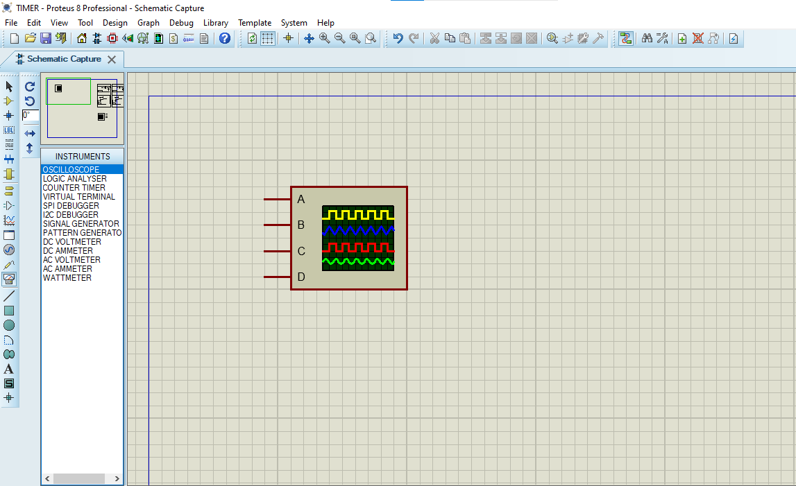
- Click on Virtual Instruments Mode then choose OSCILLOSCOPE
- Click on Terminal Mode then choose (DEFAULT & POWER &GROUND)
- finally make the circuit below and start the simulation
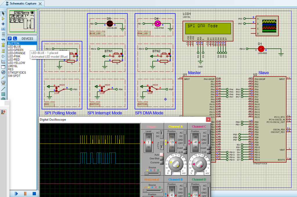
That’s all!
If you have any questions or suggestions don’t hesitate to leave a comment below.
4 comments
[…] to develop a sophisticated LED bar-graph display system. Leveraging the STM32‘s GPIO pins and SPI interface, the project efficiently manages the 74HC595 to control a series of LEDs configured in a […]
[…] across diverse embedded applications. Supporting various serial interface standards, including SPI, the ADC128S102 serves as a cornerstone in high-speed data acquisition […]
[…] microcontroller with the MAX31856 enhances temperature monitoring efficiency, primarily through SPI communication, optimizing data exchange between the components and paving the way for highly […]
[…] applications. When integrated with STM32 microcontrollers, the MCP3208 communicates seamlessly via SPI . This integration enables efficient multi-channel data acquisition and processing in embedded […]