In this article, we’ll demonstrate how to build an STM32 LED Bar–Graph Display with 74HC595 shift register. This project shows how to use the STM32 microcontroller to control multiple LEDs efficiently by expanding output pins with the 74HC595.

Things used in this project
Software apps and online services:
1- STMicroelectronics STM32CubeMX
2- STMicroelectronics STM32CubeIDE
3- Proteus 8
Creating an LED Bar-Graph Display System: Integrating STM32 with 74HC595 Shift Register
This project integrates the STM32 microcontroller with the 74HC595 shift register to develop a sophisticated LED bar-graph display system. Leveraging the STM32‘s GPIO pins and SPI interface, the project efficiently manages the 74HC595 to control a series of LEDs configured in a bar-graph layout.
Exploring the Functionality of the 74HC595 Shift Register:
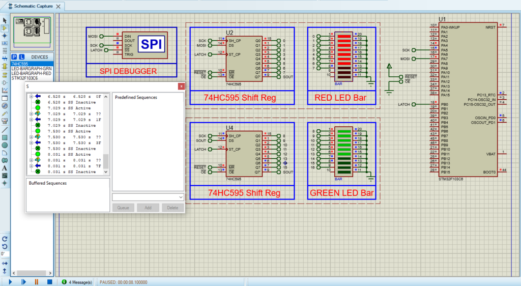
Each output of the 74HC595 is intricately connected to an individual LED, thus forming the cohesive bar-graph display. By serially shifting data into the 74HC595 and subsequently latching it to the output registers, the STM32 orchestrates precise control over the illumination of each LED within the bar-graph structure.
Understanding the Role of 74HC595 as the Master Conductor:
The 74HC595 shift register functions as the master conductor, intricately orchestrating the flow of data with finesse and accuracy. Its capability to seamlessly accept data in serial format and output it in parallel establishes the foundational framework for controlled and synchronized actions within the system. Whether tasked with managing LED screens or controlling multiple peripheral devices, the 74HC595 emerges as a versatile component within the embedded landscape.
To commence this project, our first step is to configure the STM32 in SPI Transmit-only master mode. This setup is crucial for establishing seamless communication with the 74HC595 shift register. Following that, we’ll configure the appropriate pins, such as PB1, specifically pin 12 (LATCH), as OUTPUT to ensure accurate control over peripheral devices interfaced with the shift register.
STM32CubeMX Configuration:
- Open CubeMX & Create New Project Choose The Target MCU STM32F103C6 & Double-Click Its Name
- Go To The Clock Configuration & Set The System Clock To 8MHz
Configuration of the GPIO Mode:
- Configure The GPIO Pin PA4 as Output Pin (CSPin)
Configuration of the SPI mode:
- In the Categories tab, select the SPI1 & Transmit Only Master
- In the Parametre settings set [ Prescaler (for Baud Rate) =2 && Clock Polarity = LOW && Clock Phase = 1 Edge ]
- Generate The Initialization Code & Open The Project In CubeIDE
STM32CubeIDE Configuration :
- Write The Application Layer Code
- main.c
/* Includes ------------------------------------------------------------------*/
#include "main.h"
/* Private variables ---------------------------------------------------------*/
SPI_HandleTypeDef hspi1;

/* USER CODE BEGIN PV */
uint8_t dataOut[9]={0x00,0x01,0x03,0x07,0xF,0x1F,0x3F,0x7F,0xFF};
/* USER CODE END PV */

/* Private function prototypes -----------------------------------------------*/
void SystemClock_Config(void);
static void MX_GPIO_Init(void);
static void MX_SPI1_Init(void);
/* USER CODE BEGIN PFP */
void shiftOut(uint8_t * data , uint16_t size);
/* USER CODE END PFP */

/* Private user code ---------------------------------------------------------*/
/* USER CODE BEGIN 0 */
void shiftOut(uint8_t * data , uint16_t size)
{
    HAL_GPIO_WritePin(LATCH_GPIO_Port, LATCH_Pin, GPIO_PIN_RESET);
    HAL_SPI_Transmit(&hspi1,data,size,100);
    HAL_GPIO_WritePin(LATCH_GPIO_Port, LATCH_Pin, GPIO_PIN_SET);
}
/* USER CODE END 0 */

int main(void)
{
  /* Reset of all peripherals, Initializes the Flash interface and the Systick. */
  HAL_Init();
  /* Configure the system clock */
  SystemClock_Config();
  /* Initialize all configured peripherals */
  MX_GPIO_Init();
  MX_SPI1_Init();

  /* Infinite loop */
  /* USER CODE BEGIN WHILE */
  while (1)
  {
    /* USER CODE END WHILE */

    /* USER CODE BEGIN 3 */
      for (int i=0;i<9;i++)
      {
          shiftOut(dataOut+i,1);
          HAL_Delay(500);
      }
  }
  /* USER CODE END 3 */
}
Proteus Configuration :
- Open Proteus & Create New Project and click next

- Click on Pick Device
- Search for STM32F103C6 & 74HC595 & LED-BARGRAPH- (GRN & RED)
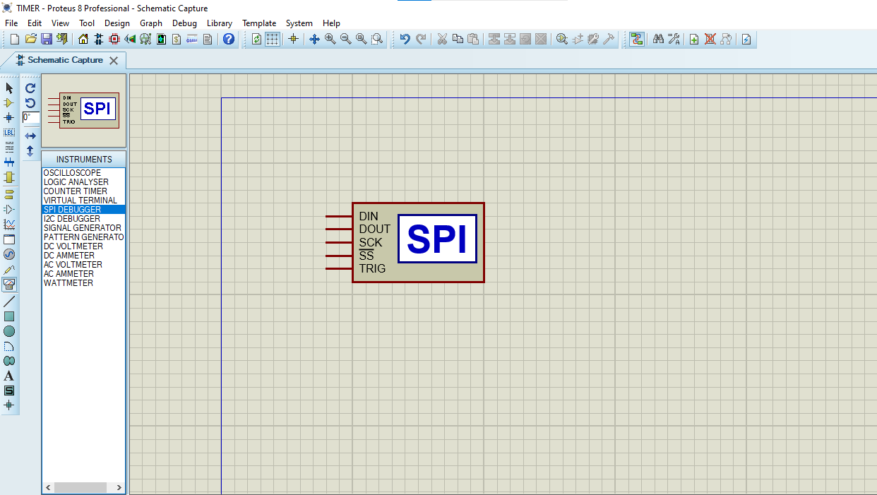
- Click on Virtual Instruments Mode then choose SPI DEBUGGER

- Click on Terminal Mode then choose (DEFAULT & POWER &GROUND)
- finally make the circuit below and start the simulation

That’s all!
If you have any questions or suggestions don’t hesitate to leave a comment below
