
In this article, we will explore the STM32 H-Bridge Motor Driver, an effective solution for controlling DC motor direction.

Things used in this project
Software apps and online services:
1- STMicroelectronics STM32CubeMX
2- STMicroelectronics STM32CubeIDE
3- Proteus 8
Introduction to H-Bridge DC Motor Control
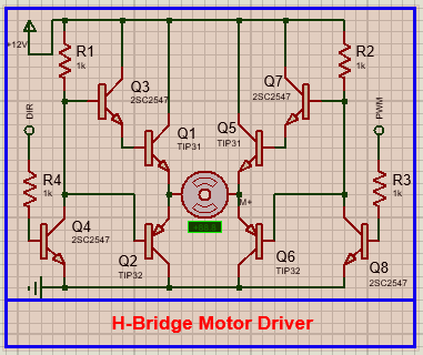
An H-Bridge DC motor control circuit is a popular method for controlling the direction and operation of direct current (DC) motors. The design gets its name from the configuration of transistors that resemble the letter “H.” This circuit is particularly effective for medium-power motors, balancing performance with the limitations of the transistors used in the design.
How the H-Bridge Works:
The H-Bridge circuit allows a DC motor to rotate in both clockwise and counterclockwise directions. This is accomplished by controlling the voltage levels at two key points in the circuit labeled “Forward” and “Reverse / Backward.”
Operating Principles
- Forward Motion:
- When a high voltage is applied to the “Forward” input, transistor Q3 becomes saturated, allowing current to flow through it.
- Concurrently, transistors Q1 and Q6 also saturate, facilitating the flow of current through the DC motor in one direction.
- Reverse Motion:
- When the “Reverse / Backward” input receives a high voltage, transistor Q7 enters the saturation region, while transistors Q5 and Q2 also activate.
- This configuration allows the current to flow through the motor in the opposite direction, reversing its rotation.
Speed Control Options
While the H-Bridge circuit efficiently controls the direction of the motor, it does not directly manage the motor’s speed. To vary the speed, you can adjust the supply voltage or implement Pulse Width Modulation (PWM) techniques.
Interfacing H-Bridge DC Motor with STM32:
To effectively control an H-Bridge DC motor using an STM32 microcontroller, follow these guidelines to ensure optimal performance and protection.
Components and Connections
Start by gathering essential components, including the STM32 microcontroller, an H-Bridge driver (such as the L298N or discrete transistors), protection diodes, and resistors. Connect the STM32’s GPIO pins to the H-Bridge’s “Forward” and “Reverse” inputs to control motor direction. Ensure the H-Bridge and motor receive an adequate power supply. Additionally, integrate fast recovery diodes across the motor terminals to protect against back EMF.
Firmware Implementation
In your firmware, configure the GPIO pins as outputs and utilize Pulse Width Modulation (PWM) for speed control. This configuration allows efficient management of the motor’s direction and velocity, providing precise control over the H-Bridge DC motor’s operation in your projects.
To kickstart this project, we will control a DC motor using an STM32 microcontroller and an H-Bridge driver. We’ll use GPIO pins and TIM2 to generate PWM signals for motor control. The code will handle user input debouncing for start/stop functions and duty cycle adjustments. Additionally, we will calculate angular acceleration and send the motor’s status via UART for real-time feedback.
STM32CubeMX Configuration:
- Open CubeMX & Create New Project Choose The Target MCU STM32F103C6 & Double-Click Its Name
- Go To The Clock Configuration & Set The System Clock To 8MHz
Configuration for the TIMER Mode:
- In the Categories tab, select the TIM2 then Enable Internal Clock & PWM Generation Channel 2
- In the Counter settings tab, set the (Prescaler = 0 & Counter Peroid = 65535)
- In the PWM Generation Channel set ( Mode : PWM mode 1 & Pulse = 0 )
Configuration for the GPIO Mode:
- Configure The GPIO Pins [PA4 , PA5] as Input Pins
- Configure The GPIO Pins [PB2] as Input Pins
Configuration for the UART Mode:
- Enable USART1 Module (Asynchronous Mode)
- Set the USART1 communication parameters (baud rate = 115200, parity=NON, stop bits =1, and word length = 8bits)
- Generate The Initialization Code & Open The Project In CubeIDE
STM32CubeIDE Configuration:
Initialization and Motor Control Functions
This section of the code includes necessary headers and initializes global variables for the motor control system. It defines functions to handle the motor’s start/stop and duty cycle changes.
- HandleStartStop: This function manages the start/stop functionality of the motor using a button. It employs debouncing to ensure stable button press detection and updates the motor state. If the motor is running, it starts PWM using Timer2; otherwise, it stops the motor.
- HandleDutyCycle: This function adjusts the motor’s duty cycle based on button presses. It increments the duty cycle value each time the button is pressed and updates the PWM signal accordingly.
/* Includes ------------------------------------------------------------------*/
#include "main.h"

/* Private includes ----------------------------------------------------------*/
#include<stdio.h>
#include<string.h>

/* Private define ------------------------------------------------------------*/
#define DEBOUNCE_DELAY 50 // ms

/* Private variables ---------------------------------------------------------*/
TIM_HandleTypeDef htim2;
UART_HandleTypeDef huart1;

uint8_t motorRunning = 0;
uint8_t currentDutyCycle = 0; // 0: 25%, 1: 50%, 2: 75%, 3: 99%
uint32_t lastDebounceTime = 0;
static uint8_t lastButtonState;

/* Function prototypes -----------------------------------------------------*/
void HandleStartStop(void);
void HandleDutyCycle(void);
void UpdatePWM(void);
void SendUartMessage(char* message);

/* Function to handle start/stop button */
void HandleStartStop(void) {
    static GPIO_PinState lastStartStopState = GPIO_PIN_SET; // Track previous state
    GPIO_PinState currentStartStopState = HAL_GPIO_ReadPin(START_STOP_GPIO_Port, START_STOP_Pin);

    if (lastStartStopState == GPIO_PIN_SET && currentStartStopState == GPIO_PIN_RESET) {
        uint32_t currentTime = HAL_GetTick();
        if (currentTime - lastDebounceTime > DEBOUNCE_DELAY) {
            motorRunning = !motorRunning;
            SendUartMessage(motorRunning ? "Motor Started\n\r" : "Motor Stopped\n\r");
            UpdatePWM();
            lastDebounceTime = currentTime;
        }
    }

    if (motorRunning) {
        HAL_GPIO_WritePin(DIR_GPIO_Port, DIR_Pin, GPIO_PIN_RESET); // Ensure DIR pin is set
        HAL_TIM_Base_Start(&htim2); // Start Timer2
        HAL_TIM_OC_Start(&htim2, TIM_CHANNEL_2); // Start PWM
    } else {
        HAL_TIM_Base_Stop(&htim2); // Stop Timer2
        HAL_TIM_OC_Stop(&htim2, TIM_CHANNEL_2); // Stop PWM
    }

    lastStartStopState = currentStartStopState; // Update last button state
}

/* Function to handle duty cycle button */
void HandleDutyCycle(void) {
    uint8_t currentButtonState = HAL_GPIO_ReadPin(DUTY_CYCLE_GPIO_Port, DUTY_CYCLE_Pin);

    if (currentButtonState != lastButtonState) {
        uint32_t currentTime = HAL_GetTick();
        if (currentTime - lastDebounceTime > DEBOUNCE_DELAY) {
            if (currentButtonState == GPIO_PIN_RESET) { // Button is pressed
                currentDutyCycle = (currentDutyCycle + 1) % 4;
                UpdatePWM();
            }
            lastDebounceTime = currentTime;
        }
    }

    lastButtonState = currentButtonState; // Update last button state
}
PWM Update and UART Communication
This part of the code focuses on updating the PWM signal and sending UART messages.
- UpdatePWM: This function calculates the PWM value based on the current duty cycle and computes the corresponding angular acceleration. It sets the PWM output using Timer2 and sends a message via UART to indicate the current duty cycle and acceleration.
- SendUartMessage: This utility function transmits a string message over UART, allowing real-time monitoring of the motor’s status and parameters.
void UpdatePWM(void) {
    if (motorRunning) {
        uint32_t pwmValue;
        char msg[100];
        float tau_max = 1.0; // Maximum torque in Nm (example value)
        float moment_of_inertia = 0.002; // Effective mass in kg·m²
        float angular_acceleration;

        switch (currentDutyCycle) {
            case 0:
                pwmValue = 65535 * 0.25; // 25% of 65535
                angular_acceleration = (0.25 * tau_max) / moment_of_inertia;
                sprintf(msg, "Duty Cycle: 25%%, Acceleration: %.2f rad/s^2\n\r", angular_acceleration);
                break;
            case 1:
                pwmValue = 65535 * 0.50; // 50% of 65535
                angular_acceleration = (0.50 * tau_max) / moment_of_inertia;
                sprintf(msg, "Duty Cycle: 50%%, Acceleration: %.2f rad/s^2\n\r", angular_acceleration);
                break;
            case 2:
                pwmValue = 65535 * 0.75; // 75% of 65535
                angular_acceleration = (0.75 * tau_max) / moment_of_inertia;
                sprintf(msg, "Duty Cycle: 75%%, Acceleration: %.2f rad/s^2\n\r", angular_acceleration);
                break;
            case 3:
                pwmValue = 65535 * 0.99; // 99% of 65535
                angular_acceleration = (0.99 * tau_max) / moment_of_inertia;
                sprintf(msg, "Duty Cycle: 99%%, Acceleration: %.2f rad/s^2\n\r", angular_acceleration);
                break;
            default:
                pwmValue = 0;
                sprintf(msg, "Duty Cycle: Error\n\r");
                break;
        }

        __HAL_TIM_SET_COMPARE(&htim2, TIM_CHANNEL_2, pwmValue);
        SendUartMessage(msg); // Send duty cycle and acceleration via UART
    } else {
        __HAL_TIM_SET_COMPARE(&htim2, TIM_CHANNEL_2, 0); // Set PWM to 0 if motor is not running
    }
}

// Function to send UART message
void SendUartMessage(char* message) {
    HAL_UART_Transmit(&huart1, (uint8_t*)message, strlen(message), HAL_MAX_DELAY);
}
main Function
The main function initializes the Hardware Abstraction Layer (HAL) and configures the system clock. It sets up GPIO, Timer2 for PWM, and UART for communication. After sending an initialization message, it enters an infinite loop, monitoring button presses to control the motor and adjust the PWM duty cycle, facilitating real-time feedback and control through UART.
int main(void)
{
    /* MCU Configuration--------------------------------------------------------*/
    HAL_Init(); // Initialize the Hardware Abstraction Layer

    /* Configure the system clock */
    SystemClock_Config(); // Set up the system clock

    /* Initialize all configured peripherals */
    MX_GPIO_Init(); // Initialize GPIO pins
    MX_TIM2_Init(); // Initialize Timer2 for PWM
    MX_USART1_UART_Init(); // Initialize UART for communication

    SendUartMessage("Initialization Completed \n\r"); // Notify that initialization is complete

    /* Infinite loop */
    while (1)
    {
        HandleStartStop(); // Check and handle start/stop button
        HandleDutyCycle(); // Check and handle duty cycle button
    }
}
Proteus Configuration :
- Open Proteus & Create New Project and click next
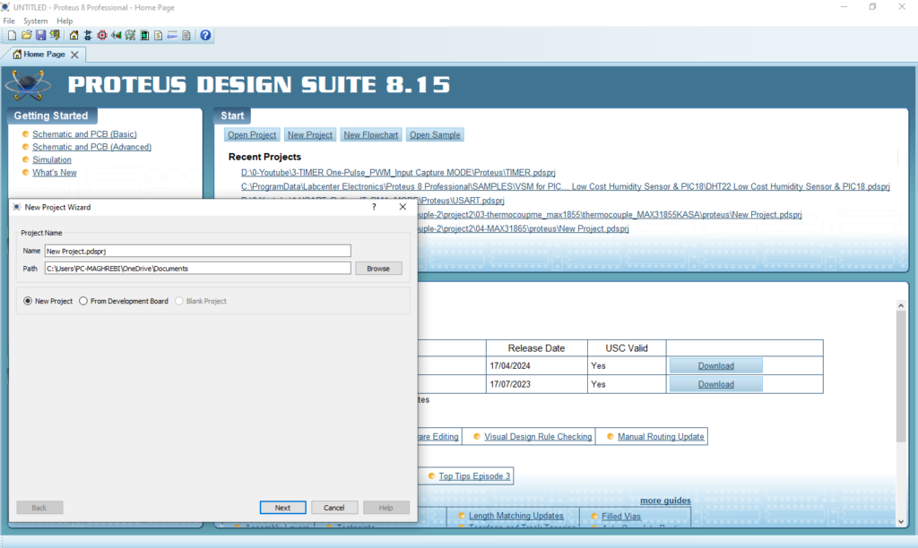
- Click on Pick Device
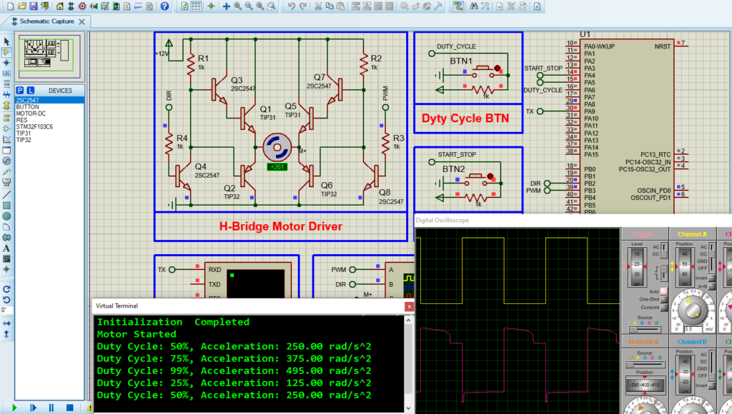
- Search for STM32F103C6 & 2CS25487 & MOTOR-DC & BUTTON & RES & TIP32 & TIP32
- Click on Virtual Instruments Mode then choose (VIRTUAL TERMINAL & OSCILLOSCOPE)
- Click on Terminal Mode then choose (DEFAULT & POWER &GROUND)
- finally make the circuit below and start the simulation
That’s all!
If you have any questions or suggestions don’t hesitate to leave a comment below
1 comment
[…] L298N is a dual H-Bridge motor driver module designed to control two DC motors simultaneously. It can handle voltages between 5V and 35V, […]