
In this article, we will explore STM32 DS18B20 integration, allowing for accurate temperature readings in embedded systems using the DS18B20 temperature sensor with an STM32 microcontroller.

Things used in this project
Software apps and online services:
1- STMicroelectronics STM32CubeMX
2- STMicroelectronics STM32CubeIDE
3- Proteus 8
Understanding the DS18B20 Temperature Sensor and Its Features
The objective of this project is to achieve STM32 DS18B20 integration by interfacing the DS18B20 temperature sensor with an STM32 microcontroller, leveraging its 1-Wire communication protocol. We will configure the STM32 to communicate with the DS18B20, acquire temperature data, and output the readings through a display or a communication interface, such as UART. This project is ideal for anyone looking to implement temperature sensing capabilities in an embedded system using STM32.
DS18B20 Overview :
The DS18B20 sensor is known for its precision and ease of use, thanks to its 1-Wire interface. Here’s an overview of the key features:
- 1-Wire Interface: Uses only one communication pin, simplifying wiring.
- Wide Operating Range: Measures temperatures from -55°C to +125°C with an accuracy of ±0.5°C from -10°C to +85°C.
- Programmable Resolution: Adjustable resolution from 9 to 12 bits.
Alarm Function: Provides non-volatile temperature threshold settings for alarms. - Power Supply Modes: Operates in either parasite power (powered via the data line) or with an external power source.
- Multidrop Capability: Multiple sensors can share the same communication bus, making it useful for systems with multiple temperature sensors.
Integration of DS18B20 with STM32:
STM32 DS18B20 Integration enables precise temperature measurement by leveraging the sensor’s 1-Wire communication protocol with the STM32 microcontroller
Hardware Connections
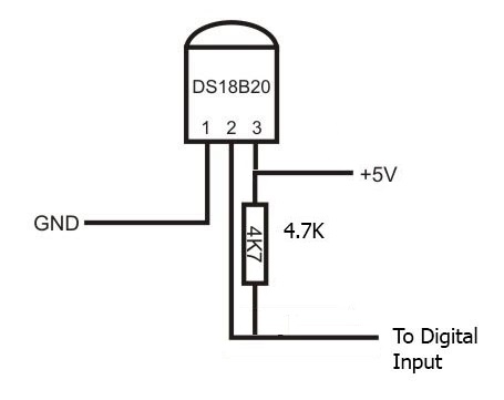
To interface the DS18B20 with the STM32, the sensor requires three connections:
- Data Line (DQ): This connects to one of the GPIO pins of the STM32 microcontroller. The same line can be used for power if the DS18B20 operates in parasite mode.
- Ground (GND): Connect this pin to the ground of the microcontroller.
- VDD (Optional): The sensor can be powered externally through this pin, though it is optional when using parasite power.
In parasite mode, a 4.7kΩ pull-up resistor is required on the data line (DQ) to ensure proper communication. The sensor can draw power directly from the data line when in this mode, as shown in the picture below.
Wire Communication Protocol
STM32 DS18B20 Integration utilizes the 1-Wire protocol, enabling communication through a single data line. The DS18B20 communicates efficiently with the STM32 microcontroller using this method, which streamlines the wiring and simplifies the design. Below is an overview of the 1-Wire commands and communication process:
- Reset Pulse: The STM32 initiates communication by sending a reset pulse to the DS18B20, pulling the DQ line low for a minimum of 480 µs. The DS18B20 responds with a presence pulse to acknowledge the connection.
- ROM Commands: After the reset, the STM32 sends ROM function commands such as Read ROM, Match ROM, or Skip ROM to identify and address the DS18B20 sensor.
- Temperature Conversion: The Convert T command (44h) is sent to trigger a temperature conversion. The sensor will then process the temperature data, which can take from 94 ms to 750 ms, depending on the resolution.
- Read Temperature: Once the temperature conversion is complete, the STM32 sends the Read Scratchpad command (BEh) to retrieve the temperature data from the DS18B20’s scratchpad memory. The temperature data is stored in two bytes (LSB and MSB) and must be processed to obtain the final temperature value.
Memory Command Functions
The DS18B20 has several memory-related commands to store and retrieve data:
- Write Scratchpad (4Eh): Writes to the sensor’s scratchpad, storing user-defined values such as high and low alarm triggers.
- Read Scratchpad (BEh): Reads the entire scratchpad, which contains 9 bytes, including temperature data and CRC verification.
- Copy Scratchpad (48h): Copies the scratchpad contents to the DS18B20’s non-volatile EEPROM memory. This is useful for saving alarm thresholds and configuration settings.
- Recall E2 (B8h): Recalls the temperature trigger values and configuration settings from EEPROM into the scratchpad.
- Read Power Supply (B4h): Checks if the DS18B20 is running on parasite power or an external supply.
Temperature Conversion Commands
- Convert T (44h): Initiates temperature measurement. The DS18B20 outputs 0 on the bus during conversion and returns 1 when it’s done.
- Strong Pull-up: If operating in parasite power mode, a strong pull-up must be provided during the conversion and copying phases to ensure sufficient power.
To kickstart this project, we will configure the STM32 microcontroller to interface with the DS18B20 temperature sensor and display temperature readings via UART. Specifically, we will utilize the HAL library to manage UARTcommunication and leverage the DWT (Data Watchpoint and Trace) for precise microsecond delays. In addition, we will set up GPIO pins to facilitate interaction with the sensor, thereby controlling the data flow between the STM32 and the DS18B20. This configuration enables continuous temperature monitoring, providing real-time data over UARTwhile toggling an LED to indicate system activity. Overall, this setup offers a simple yet effective way to manage and visualize temperature data.
STM32CubeMX Configuration:
- Open CubeMX & Create New Project Choose The Target MCU STM32F103C6 & Double-Click Its Name
- Go To The Clock Configuration & Set The System Clock To 16MHz
Configuration for the GPIO Mode:
- Configure The GPIO Pins [PA1] as Output Pins
- Configure The GPIO Pins [PC13] as Output Pins
Configuration for the UART Mode:
- Enable USART1 Module (Asynchronous Mode)
- Set the USART1 communication parameters (baud rate = 115200, parity=NON, stop bits =1, and word length = 8bits)
- Generate The Initialization Code & Open The Project In CubeIDE
STM32CubeIDE Configuration:
Now, let’s implement the code that reads the temperature from the DS18B20 sensor. This code will send the data via UART to a serial monitor while toggling an LED at regular intervals to indicate system activity.
DS18B20 Sensor Communication:
To read the temperature, we will use the OneWire protocol, which communicates over a single data line. The DS18B20 sensor requires us to send specific commands and read its scratchpad memory to retrieve the temperature data.
#include "ds18b20.h"
#include "uart.h"
#include "string.h"
#include "stdio.h"

// DS18B20 Functions
float DS18b20_temp(void) {
    uint8_t temp_lsb, temp_msb;
    int16_t raw_temp;

    onewire_reset();       // Initialize communication
    onewire_Write(0xCC);   // Skip ROM command
    onewire_Write(0x44);   // Start temperature conversion
    HAL_Delay(750);        // Wait for conversion (750 ms for 12-bit resolution)

    onewire_reset();       // Reset the bus
    onewire_Write(0xCC);   // Skip ROM command
    onewire_Write(0xBE);   // Read Scratchpad

    // Read temperature data
    temp_lsb = onewire_Read();
    temp_msb = onewire_Read();

    // Convert raw temperature to Celsius
    raw_temp = (temp_msb << 8) | temp_lsb;
    return (float)raw_temp / 16.0;
}

void delay_us_dwt_init(void) {
    CoreDebug->DEMCR |= CoreDebug_DEMCR_TRCENA_Msk;  // Enable DWT
    DWT->CTRL |= DWT_CTRL_CYCCNTENA_Msk;             // Enable cycle counter
}

void delay_us_dwt(uint32_t us) {
    uint32_t start_cycle = DWT->CYCCNT;
    uint32_t delay_cycles = (HAL_RCC_GetHCLKFreq() / 1000000) * us;
    while ((DWT->CYCCNT - start_cycle) < delay_cycles);
}

uint8_t onewire_reset(void) {
    uint8_t sensor_present = 0;

    Output_Pin(ONEWIRE_GPIO_Port, ONEWIRE_Pin);
    HAL_GPIO_WritePin(ONEWIRE_GPIO_Port, ONEWIRE_Pin, GPIO_PIN_RESET);
    delay_us_dwt(480);  // Pull low for 480µs

    Input_Pin(ONEWIRE_GPIO_Port, ONEWIRE_Pin);
    delay_us_dwt(60);   // Wait for sensor response

    if (HAL_GPIO_ReadPin(ONEWIRE_GPIO_Port, ONEWIRE_Pin) == GPIO_PIN_RESET) {
        sensor_present = 1;
    }

    delay_us_dwt(480);  // Complete the reset sequence
    return sensor_present;
}

void onewire_Write(uint8_t dato) {
    for (int i = 0; i < 8; i++) {
        if (dato & (1 << i)) {
            Output_Pin(ONEWIRE_GPIO_Port, ONEWIRE_Pin);
            HAL_GPIO_WritePin(ONEWIRE_GPIO_Port, ONEWIRE_Pin, GPIO_PIN_RESET);
            delay_us_dwt(6);
            Input_Pin(ONEWIRE_GPIO_Port, ONEWIRE_Pin);
            delay_us_dwt(64);
        } else {
            Output_Pin(ONEWIRE_GPIO_Port, ONEWIRE_Pin);
            HAL_GPIO_WritePin(ONEWIRE_GPIO_Port, ONEWIRE_Pin, GPIO_PIN_RESET);
            delay_us_dwt(60);
            Input_Pin(ONEWIRE_GPIO_Port, ONEWIRE_Pin);
            delay_us_dwt(10);
        }
    }
}

uint8_t onewire_Read(void) {
    uint8_t read_byte = 0;
    for (int i = 0; i < 8; i++) {
        Output_Pin(ONEWIRE_GPIO_Port, ONEWIRE_Pin);
        HAL_GPIO_WritePin(ONEWIRE_GPIO_Port, ONEWIRE_Pin, GPIO_PIN_RESET);
        delay_us_dwt(6);
        Input_Pin(ONEWIRE_GPIO_Port, ONEWIRE_Pin);
        delay_us_dwt(9);
        if (HAL_GPIO_ReadPin(ONEWIRE_GPIO_Port, ONEWIRE_Pin) == GPIO_PIN_SET) {
            read_byte |= (1 << i);
        }
        delay_us_dwt(55);
    }
    return read_byte;
}
GPIO Pin Configuration:
In this code, GPIO pins are configured dynamically as either input or output based on the OneWire communication requirements.
void Input_Pin(GPIO_TypeDef *GPIOx, uint16_t GPIO_Pin) {
    uint32_t position = 0;
    uint32_t register_offset;
    volatile uint32_t *config_register;
    uint32_t temp;

    while (GPIO_Pin) {
        if (GPIO_Pin & 0x01) {
            register_offset = (position < 8) ? 0 : 1;
            config_register = &GPIOx->CRL + register_offset;
            temp = *config_register;
            temp &= ~(0x0F << ((position & 0x07) * 4));
            temp |= (0x04 << ((position & 0x07) * 4));  // Input floating
            *config_register = temp;
        }
        position++;
        GPIO_Pin >>= 1;
    }
}

void Output_Pin(GPIO_TypeDef *GPIOx, uint16_t GPIO_Pin) {
    uint32_t position = 0;
    uint32_t register_offset;
    volatile uint32_t *config_register;
    uint32_t temp;

    while (GPIO_Pin) {
        if (GPIO_Pin & 0x01) {
            register_offset = (position < 8) ? 0 : 1;
            config_register = &GPIOx->CRL + register_offset;
            temp = *config_register;
            temp &= ~(0x0F << ((position & 0x07) * 4));
            temp |= (0x01 << ((position & 0x07) * 4));  // Output push-pull
            *config_register = temp;
        }
        position++;
        GPIO_Pin >>= 1;
    }
}
UART Communication:
UART communication is implemented to transmit temperature data to a serial terminal. The functions handle writing individual characters and strings over UART.
#include "uart.h"

void uartx_write(UART_HandleTypeDef *huart, uint8_t ch) {
    HAL_UART_Transmit(huart, &ch, 1, HAL_MAX_DELAY);
}

void uartx_write_text(UART_HandleTypeDef *huart, char *info) {
    HAL_UART_Transmit(huart, (uint8_t *)info, strlen(info), HAL_MAX_DELAY);
}
Main Program:
The main loop reads temperature values from the DS18B20 sensor, sends the data over UART, and toggles an LED every 800 milliseconds to indicate activity.
int main(void) {
    HAL_Init();
    SystemClock_Config();
    MX_GPIO_Init();
    MX_USART1_UART_Init();

    delay_us_dwt_init();  // Initialize the DWT for delays
    uartx_write_text(&huart1, "Initialization complete\r\n");

    while (1) {
        float temperature = DS18b20_temp();  // Get temperature
        char buffer[50];
        sprintf(buffer, "Temperature = %.2f°C\r\n", temperature);
        uartx_write_text(&huart1, buffer);  // Send temperature over UART
        HAL_Delay(800);  // Wait before next read
        HAL_GPIO_TogglePin(led_GPIO_Port, led_Pin);  // Toggle LED
    }
}
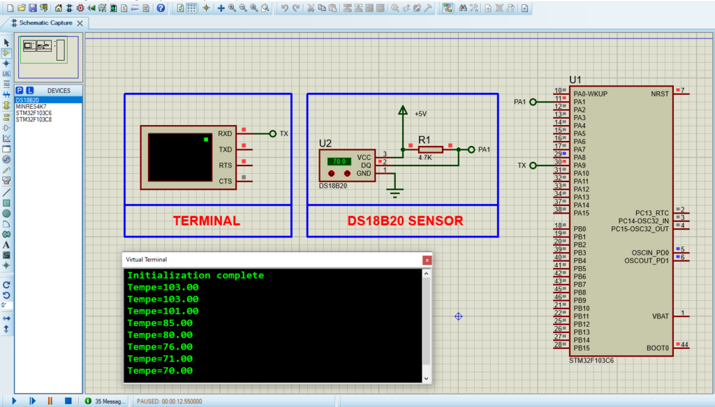
Proteus Configuration :
- Open Proteus & Create New Project and click next
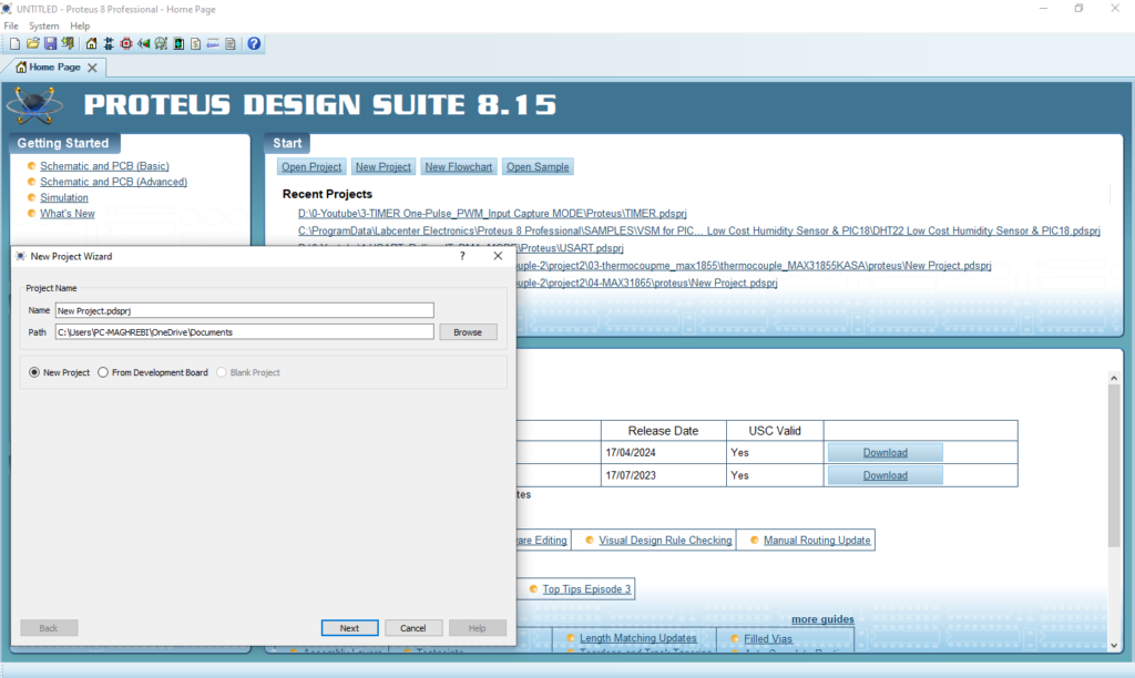
- Click on Pick Device
- Search for STM32F103C6 & LED-RED & LED-GREEN , LED_BLUE, TMP36
- Click on Virtual Instruments Mode then choose Terminal
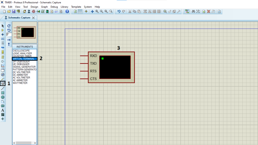
- Click on Terminal Mode then choose (DEFAULT & POWER &GROUND)
- finally make the circuit below and start the simulation
That’s all!
If you have any questions or suggestions don’t hesitate to leave a comment below.
1 comment
[…] more details on the DS18B20 sensor and its integration with microcontrollers, please refer to the linked […]