In this article, we explore the STM32 MAX31855 Thermocouple Interface, focusing on integrating the Type K thermocouple with STM32 microcontrollers for accurate temperature measurement.

Things used in this project
Software apps and online services:
1- STMicroelectronics STM32CubeMX
2- STMicroelectronics STM32CubeIDE
3- Proteus 8
Enhancing Temperature Monitoring with STM32 and MAX31855 Integration
The project involves harnessing the power of STM32 microcontrollers in tandem with the MAX31855 thermocouple interface chip to achieve precise temperature detection capabilities. With the ever-increasing demand for accurate temperature monitoring in various industries, the integration of these components provides a robust solution for engineers and developers looking to improve the performance of their systems
Exploring Thermocouple Technology and its Applications:
Thermocouples represent a fundamental temperature sensing technology renowned for their simplicity and reliability. Unlike semiconductor-based sensors, thermocouples operate by exploiting the voltage generated across two different metal wires welded together. This inherent physical principle enables thermocouples to measure temperatures across a wide range, from cryogenic levels to extreme heat.
Understanding the MAX31855 Thermocouple Interface Chip:
At the heart of the project lies the MAX31855 thermocouple interface chip, a versatile solution designed to streamline temperature sensing tasks. With its ability to perform cold-junction compensation and digitize signals from various thermocouple types, including K-, J-, N-, T-, S-, R-, and E-types, the MAX31855 offers unparalleled flexibility and accuracy. Its SPI-compatible interface and high-resolution temperature conversion capabilities make it an ideal choice for demanding applications.
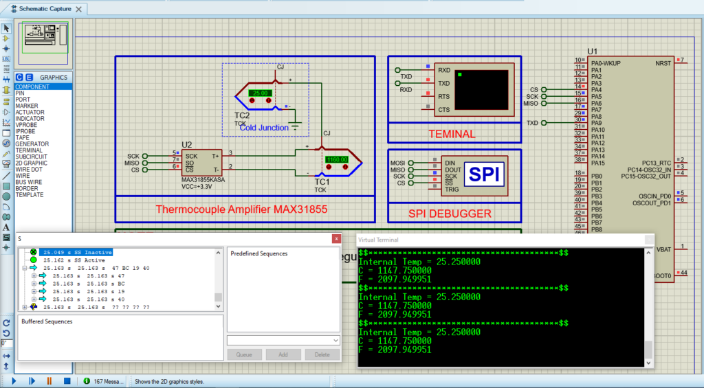
To initiate this project, we’ll begin by configuring the STM32 SPI Full-Duplex Master mode. Following that, we’ll proceed to configure the PA4 pin as an OUTPUT. Finally, we’ll set up UART communication to transmit both the temperature readings and system status. This foundational setup establishes the framework for integrating the STM32 microcontroller with the MAX31855 thermocouple interface chip, specifically tailored for type K thermocouples
STM32CubeMX Configuration:
- Open CubeMX & Create New Project Choose The Target MCU STM32F103C6 & Double-Click Its Name
- Go To The Clock Configuration & Set The System Clock To 8MHz
- Configure The GPIO Pin PA4 as Output Pin (CSPin)
- In the Categories tab, select the SPI1 & Full-Duplex Master
- Enable USART1 Module (Asynchronous Mode)
- Set the USART1 communication parameters (baud rate = 9600, parity=NON, stop bits = 1, and word length =8bits)
- Generate The Initialization Code & Open The Project In CubeIDE
STM32CubeIDE Configuration :
- Write The Application Layer Code
- Max31855.h & Max31856.c
- main.c
/*
 * Max31855.h
 * Author: Marwen Maghrebi
 */

#ifndef INC_MAX31855_H_
#define INC_MAX31855_H_

#include <main.h>
#include<stdbool.h>
#include<math.h>

extern bool initialized;


#define MAX31855_FAULT_NONE (0x00)      ///< Disable all fault checks
#define MAX31855_FAULT_OPEN (0x01)      ///< Enable open circuit fault check
#define MAX31855_FAULT_SHORT_GND (0x02) ///< Enable short to GND fault check
#define MAX31855_FAULT_SHORT_VCC (0x04) ///< Enable short to VCC fault check
#define MAX31855_FAULT_ALL (0x07)       ///< Enable all fault checks

#define SPI_DELAY 0xFF
/**************************************************************************/
/*!
    @brief  Sensor driver for the Adafruit MAX31855 thermocouple breakout.
*/
/**************************************************************************/
  bool begin(void);
  double readInternal(void);
  double readCelsius(void);
  double readFahrenheit(void);
  uint8_t readError();
  void setFaultChecks(uint8_t faults);
  uint32_t spiread32(void);
#endif /* INC_MAX31855_H_ */
/*
 * Max31855.c
 * Author: Marwen Maghrebi
 */
#include "Max31855.h"

extern SPI_HandleTypeDef hspi1;
bool initialized = false;
uint8_t faultMask = MAX31855_FAULT_ALL;

/**************************************************************************/
/*!
    @brief  Setup the HW
    @return True if the device was successfully initialized, otherwise false.
*/
/**************************************************************************/
bool begin(void) {
  if (HAL_SPI_Init(&hspi1) == HAL_OK) {initialized = true;} else {initialized = false;}
  return initialized;
}
/**************************************************************************/
/*!
    @brief  Read 4 bytes (32 bits) from breakout over SPI.
    @return The raw 32 bit value read.
*/
/**************************************************************************/
uint32_t spiread32(void) {
  uint32_t d = 0;
  uint8_t buf[4];

  // backcompatibility!
  if (!initialized) {
    begin();
  }

  HAL_GPIO_WritePin(GPIOA , SPI1_CS_Pin, GPIO_PIN_RESET);
  HAL_SPI_Receive(&hspi1, buf, sizeof(buf), SPI_DELAY);
  HAL_GPIO_WritePin(GPIOA , SPI1_CS_Pin, GPIO_PIN_SET);

  d = buf[0];
  d <<= 8;
  d |= buf[1];
  d <<= 8;
  d |= buf[2];
  d <<= 8;
  d |= buf[3];

  return d;
}

/**************************************************************************/
/*!
    @brief  Read the internal temperature.
    @return The internal temperature in degrees Celsius.
*/
/**************************************************************************/
double readInternal(void) {
  uint32_t v;

  v = spiread32();

  // ignore bottom 4 bits - they're just thermocouple data
  v >>= 4;

  // pull the bottom 11 bits off
  float internal = v & 0x7FF;
  // check sign bit!
  if (v & 0x800) {
    // Convert to negative value by extending sign and casting to signed type.
    int16_t tmp = 0xF800 | (v & 0x7FF);
    internal = tmp;
  }
  internal *= 0.0625; // LSB = 0.0625 degrees
  return internal;
}

/**************************************************************************/
/*!
    @brief  Read the thermocouple temperature.
    @return The thermocouple temperature in degrees Celsius.
*/
/**************************************************************************/
double readCelsius(void) {

  int32_t v;

  v = spiread32();

  if (v & faultMask) {
    // uh oh, a serious problem!
    return NAN;
  }

  if (v & 0x80000000) {
    // Negative value, drop the lower 18 bits and explicitly extend sign bits.
    v = 0xFFFFC000 | ((v >> 18) & 0x00003FFF);
  } else {
    // Positive value, just drop the lower 18 bits.
    v >>= 18;
  }
  double centigrade = v;

  // LSB = 0.25 degrees C
  centigrade *= 0.25;
  return centigrade;
}

/**************************************************************************/
/*!
    @brief  Read the error state.
    @return The error state.
*/
/**************************************************************************/
uint8_t readError() { return spiread32() & 0x7; }

/**************************************************************************/
/*!
    @brief  Read the thermocouple temperature.
    @return The thermocouple temperature in degrees Fahrenheit.
*/
/**************************************************************************/
double readFahrenheit(void) {
  float f = readCelsius();
  f *= 9.0;
  f /= 5.0;
  f += 32;
  return f;
}

/**************************************************************************/
/*!
    @brief  Set the faults to check when reading temperature. If any set
    faults occur, temperature reading will return NAN.

    @param faults Faults to check. Use logical OR combinations of preset
    fault masks: MAX31855_FAULT_OPEN, MAX31855_FAULT_SHORT_GND,
    MAX31855_FAULT_SHORT_VCC. Can also enable/disable all fault checks
    using: MAX31855_FAULT_ALL or MAX31855_FAULT_NONE.
*/
/**************************************************************************/
void setFaultChecks(uint8_t faults) {
  faultMask = faults & 0x07;
}
/* Includes ------------------------------------------------------------------*/
#include "main.h"
/* Private includes ----------------------------------------------------------*/
/* USER CODE BEGIN Includes */
#include "Max31855.h"
#include<stdio.h>
#include<string.h>
#include <math.h>

/* Private variables ---------------------------------------------------------*/
SPI_HandleTypeDef hspi1;
UART_HandleTypeDef huart1;

/* Private function prototypes -----------------------------------------------*/
void SystemClock_Config(void);
static void MX_GPIO_Init(void);
static void MX_SPI1_Init(void);
static void MX_USART1_UART_Init(void);


int main(void)
{
/* USER CODE BEGIN 1 */
char MSG[100]="MAX31855 test\n\r";
char MSG0[100]="Initializing sensor...\n\r";
char MSG1[100]="ERROR\n\r";
char MSG2[100]="DON. \n\r ";
char MSG3[100]="Thermocouple fault(s) detected!\n\r";
char MSG4[100]="FAULT: Thermocouple is open - no connections.\n\r";
char MSG5[100]="FAULT: Thermocouple is short-circuited to GND.\n\r";
char MSG6[100]="FAULT: Thermocouple is short-circuited to VCC.\n\r";
char MSG7[100];
char MSG8[100];
char MSG9[100]="$$***************************************$$\n\r";
char MSG10[100];
/* USER CODE END 1 */

HAL_Init();
SystemClock_Config();
MX_GPIO_Init();
MX_SPI1_Init();
MX_USART1_UART_Init();

/* USER CODE BEGIN 2 */
HAL_UART_Transmit(&huart1,(uint8_t*)MSG,sizeof(MSG), 100);
HAL_UART_Transmit(&huart1,(uint8_t*)MSG0,sizeof(MSG0), 100);
if (!begin()) {
HAL_UART_Transmit(&huart1,(uint8_t*)MSG1,sizeof(MSG1), 100);
while (1) HAL_Delay(10);
}
HAL_UART_Transmit(&huart1,(uint8_t*)MSG2,sizeof(MSG2), 100);
/* USER CODE END 2 */

while (1)
{
    sprintf(MSG10,"Internal Temp = %f \n\r",readInternal());
    HAL_UART_Transmit(&huart1,(uint8_t*)MSG10, sizeof(MSG10), 100);
    double c = readCelsius();
    if (!isnan(c)) {
        sprintf(MSG7,"C = %f \n\r",c);
        HAL_UART_Transmit(&huart1,(uint8_t*)MSG7, sizeof(MSG7), 100);
        sprintf(MSG8,"F = %f \n\r",readFahrenheit());
        HAL_UART_Transmit(&huart1,(uint8_t*)MSG8, sizeof(MSG8), 100);
        HAL_UART_Transmit(&huart1,(uint8_t*)MSG9, sizeof(MSG9), 100);
        HAL_Delay(1000);
    }
else
{
HAL_UART_Transmit(&huart1,(uint8_t*) MSG3, sizeof(MSG3), 100);
uint8_t e = readError();
    if (e & MAX31855_FAULT_OPEN)      HAL_UART_Transmit(&huart1, (uint8_t*) MSG4, sizeof(MSG4), 100);
    if (e & MAX31855_FAULT_SHORT_GND) HAL_UART_Transmit(&huart1, (uint8_t*) MSG5, sizeof(MSG5), 100);
    if (e & MAX31855_FAULT_SHORT_VCC) HAL_UART_Transmit(&huart1, (uint8_t*) MSG6, sizeof(MSG6), 100);
}}}
Proteus Configuration :
- Open Proteus & Create New Project and click next

- Click on Pick Device
- Search for STM32F103C6 & TCK & MAX31855KAKS
- Click on Virtual Instrumets Mode then choose VIRTUAL TERMINAL & SPI DEBUGGER
- Click on Terminal Mode then choose (DEFAULT & POWER &GROUND)
- finally make the circuit below and start the simulation

That’s all!
If you have any questions or suggestions don’t hesitate to leave a comment below

2 comments
Hi,
Thanks for the tutorial. How can I get the temperature readings directly from my STM microcontroller (as a variable in ‘Watch’ mode) without resorting to Proteus?
Thank you for your question! To get temperature readings directly from your STM32 microcontroller in ‘Watch’ mode using STM32CubeIDE, you need to connect your STM32 to your PC with a debugger (like ST-Link) and set up the IDE for hardware communication. Unfortunately, this cannot be done using Proteus simulation