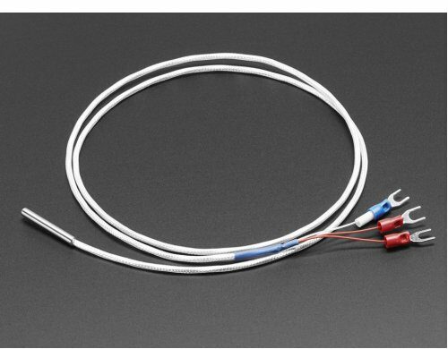
In this article, we’ll explore STM32 & MAX31865: SPI Temperature Sensing, highlighting the integration of the STM32 microcontroller with the MAX31865 through SPI.

Things used in this project
Software apps and online services
1- STMicroelectronics STM32CubeMX
2- STMicroelectronics STM32CubeIDE
3- Proteus 8
MAX31865 RTD PT100 Amplifier Integration with STM32 for Precision Temperature Sensing:
This project involves achieving precise temperature sensing capabilities through efficient SPI communication between STM32 microcontrollers and the MAX31865 RTD-to-digital converter. Delve into the intricacies of configuring and optimizing SPI communication between STM32 and MAX31865 to facilitate seamless data exchange.
Exploring the MAX31865 RTD-to-Digital Converter:
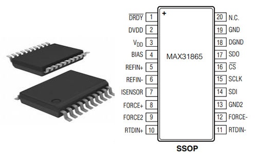
The MAX31865 is equipped with sophisticated signal conditioning circuitry optimized for PT100 through PT1000 RTDs. Its built-in 15-bit ADC, input protection, and digital controller ensure accurate temperature measurements while supporting fault detection mechanisms. 
Through SPI-compatible communication, the MAX31865 interfaces seamlessly with STM32 microcontrollers, enabling real-time temperature data acquisition and analysis

Configuring STM32 for Efficient SPI Communication:
The SPI communication between STM32 and MAX31865 is based on four essential pins: SDO (serial data output), SDI (serial data input), CS (chip selection) and SCLK (serial clock). The STM32 microcontroller serves as the master device, generating the serial clock signal (SCLK) to synchronize the data transfer.
Efficient SPI communication not only boosts data transfer speed but also ensures system reliability. By fine-tuning parameters like clock frequency and transfer mode, delays are minimized, and efficiency is maximized. Additionally, incorporating fault detection mechanisms enhances system robustness, detecting and mitigating errors to maintain data integrity
To initiate this project, we’ll commence by configuring the STM32 in SPI Full-Duplex Master mode, a crucial step in establishing seamless communication with the MAX31865. Subsequently, we’ll configure the PA4 and PA3 pins as OUTPUT to ensure precise control over peripheral devices. Finally, we’ll implement UART communication, enabling the transmission of temperature readings and system status updates with precision and efficiency
STM32CubeMX Configuration:
- Open CubeMX & Create New Project Choose The Target MCU STM32F103C6 & Double-Click Its Name
- Go To The Clock Configuration & Set The System Clock To 16MHz
- Enable USART1 and USART2 Module (Asynchronous Mode)
- Set the USART1 and USART2 communication parameters (baud rate = 9600, parity=NON, stop bits =1, and word length =8bits)
- In the NVIC settings tab, enable the interrupt for the USART1 peripheral
- In the DMA settings tab, enable the DMA for the USART2 peripheral
- Configure The GPIO Pins PB0, and PB1 as Input Pin
- Configure The GPIO Pins PB14, and PB15 as Output Pin
- Generate The Initialization Code & Open The Project In CubeIDE
STM32CubeIDE Configuration:
- Write The Application Layer Code
- Max31865.h & Max31865.c
- main.c
/*
* MAX31865.h
* Author: Marwen Maghrebi
*/

#ifndef INC_MAX31865_H_
#define INC_MAX31865_H_

#include <main.h>
#include <stdbool.h>
#include <math.h>

// MAX31865 register addresses and configuration bit masks
#define MAX31865_CONFIG_REG       0x00
#define MAX31865_CONFIG_BIAS      0x80
#define MAX31865_CONFIG_MODEAUTO  0x40
#define MAX31865_CONFIG_MODEOFF   0x00
#define MAX31865_CONFIG_1SHOT     0x20
#define MAX31865_CONFIG_3WIRE     0x10
#define MAX31865_CONFIG_24WIRE    0x00
#define MAX31865_CONFIG_FAULTSTAT 0x02
#define MAX31865_CONFIG_FILT50HZ  0x01
#define MAX31865_CONFIG_FILT60HZ  0x00

#define MAX31865_RTDMSB_REG       0x01
#define MAX31865_RTDLSB_REG       0x02
#define MAX31865_HFAULTMSB_REG    0x03
#define MAX31865_HFAULTLSB_REG    0x04
#define MAX31865_LFAULTMSB_REG    0x05
#define MAX31865_LFAULTLSB_REG    0x06
#define MAX31865_FAULTSTAT_REG    0x07

#define MAX31865_FAULT_HIGHTHRESH 0x80
#define MAX31865_FAULT_LOWTHRESH  0x40
#define MAX31865_FAULT_REFINLOW   0x20
#define MAX31865_FAULT_REFINHIGH  0x10
#define MAX31865_FAULT_RTDINLOW   0x08
#define MAX31865_FAULT_OVUV       0x04

#define RTD_A 3.9083e-3
#define RTD_B -5.775e-7

#define SPI_DELAY 0xFF
extern bool initialized;

// Number of wires configuration for the RTD sensor
typedef enum max31865_numwires {
    MAX31865_2WIRE = 0,
    MAX31865_3WIRE = 1,
    MAX31865_4WIRE = 0
} max31865_numwires_t;

// Fault detection cycle mode
typedef enum {
    MAX31865_FAULT_NONE = 0,
    MAX31865_FAULT_AUTO,
    MAX31865_FAULT_MANUAL_RUN,
    MAX31865_FAULT_MANUAL_FINISH
} max31865_fault_cycle_t;

// Function prototypes
bool begin(max31865_numwires_t wires);
uint8_t  readFault(max31865_fault_cycle_t fault_cycle);
uint8_t  readRegister8(uint8_t addr);
uint16_t readRegister16(uint8_t addr);
uint16_t readRTD(void);
uint16_t getLowerThreshold(void);
uint16_t getUpperThreshold(void);

void clearFault(void);
void setThresholds(uint16_t lower, uint16_t upper);
void setWires(max31865_numwires_t wires);
void autoConvert(bool b);
void enable50Hz(bool b);
void enableBias(bool b);
void writeRegister8(uint8_t addr, uint8_t reg);
void readRegisterN(uint8_t addr, uint8_t buffer[], uint8_t n);

float temperature(float RTDnominal, float refResistor);
float calculateTemperature(uint16_t RTDraw, float RTDnominal, float refResistor);
#endif /* INC_MAX31865_H_ */
/*
 * MAX31865.c
 *
 *  Created on: Feb 19, 2024
 *      Author: Marwen Maghrebi
 */

#include "MAX31865.h"

extern SPI_HandleTypeDef hspi1;
bool initialized = false;


/**
 * @brief Write an 8-bit value to the specified register.
 * @param addr Register address.
 * @param data Data to write.
 */
void writeRegister8(uint8_t addr, uint8_t data) {
    addr |= 0x80; // MSB=1 for write, make sure top bit is set

    uint8_t buffer[2] = {addr, data};

    HAL_GPIO_WritePin(CS_GPIO_Port, CS_Pin, GPIO_PIN_RESET);
    HAL_SPI_Transmit(&hspi1, buffer, 2, SPI_DELAY);
    HAL_GPIO_WritePin(CS_GPIO_Port, CS_Pin, GPIO_PIN_SET);
}
/**
 * @brief Read multiple bytes from the specified register.
 * @param addr Register address.
 * @param buffer Buffer to store the read data.
 * @param n Number of bytes to read.
 */
void readRegisterN(uint8_t addr, uint8_t buffer[], uint8_t n) {
    addr &= 0x7F; // MSB=0 for read, make sure top bit is not set

    HAL_GPIO_WritePin(CS_GPIO_Port, CS_Pin, GPIO_PIN_RESET);
    HAL_SPI_Transmit(&hspi1, &addr, 1, SPI_DELAY);
    HAL_SPI_Receive(&hspi1, buffer, n, SPI_DELAY);
    HAL_GPIO_WritePin(CS_GPIO_Port, CS_Pin, GPIO_PIN_SET);
}

/**
 * @brief Read an 8-bit value from the specified register.
 * @param addr Register address.
 * @return 8-bit value read from the register.
 */
uint8_t readRegister8(uint8_t addr) {
    uint8_t ret = 0;
    readRegisterN(addr, &ret, 1);
    return ret;
}

/**
 * @brief Read a 16-bit value from the specified register.
 * @param addr Register address.
 * @return 16-bit value read from the register.
 */
uint16_t readRegister16(uint8_t addr) {
    uint8_t buffer[2] = {0, 0};
    readRegisterN(addr, buffer, 2);

    uint16_t ret = (uint16_t)buffer[0]; // Cast to uint16_t before left shift
    ret <<= 8;
    ret |= buffer[1];

    return ret;
}

/**
 * @brief Read a 24-bit value from the specified register.
 * @param addr Register address.
 * @return 24-bit value read from the register.
 */
uint32_t readRegister24(uint8_t addr) {
    uint8_t buffer[3] = {0, 0, 0};
    readRegisterN(addr, buffer, 3);

    uint32_t ret = (uint32_t)buffer[0];
    ret <<= 8;
    ret |= buffer[1];
    ret <<= 8;
    ret |= buffer[2];

    return ret;
}
/**
 * @brief Set the number of wires for the RTD configuration.
 * @param wires Number of wires configuration (2, 3, or 4-wire).
 */
void setWires(max31865_numwires_t wires) {
    uint8_t t = readRegister8(MAX31865_CONFIG_REG);
    if (wires == MAX31865_3WIRE) {
        t |= MAX31865_CONFIG_3WIRE;
    } else {
        t &= ~MAX31865_CONFIG_3WIRE;
    }
    writeRegister8(MAX31865_CONFIG_REG, t);
}
/**
 * @brief Enable or disable the bias voltage on the RTD sensor.
 * @param b True to enable, false to disable.
 */
void enableBias(bool b) {
    uint8_t t = readRegister8(MAX31865_CONFIG_REG);
    if (b) {
        t |= MAX31865_CONFIG_BIAS; // Enable bias
    } else {
        t &= ~MAX31865_CONFIG_BIAS; // Disable bias
    }
    writeRegister8(MAX31865_CONFIG_REG, t);
}

/**
 * @brief Enable or disable automatic conversion mode.
 * @param b True to enable, false to disable.
 */
void autoConvert(bool b) {
    uint8_t t = readRegister8(MAX31865_CONFIG_REG);
    if (b) {
        t |= MAX31865_CONFIG_MODEAUTO; // Enable auto convert
    } else {
        t &= ~MAX31865_CONFIG_MODEAUTO; // Disable auto convert
    }
    writeRegister8(MAX31865_CONFIG_REG, t);
}

/**
 * @brief Enable or disable 50Hz filter.
 * @param b True to enable, false to disable.
 */
void enable50Hz(bool b) {
    uint8_t t = readRegister8(MAX31865_CONFIG_REG);
    if (b) {
        t |= MAX31865_CONFIG_FILT50HZ;
    } else {
        t &= ~MAX31865_CONFIG_FILT50HZ;
    }
    writeRegister8(MAX31865_CONFIG_REG, t);
}

/**
 * @brief Set the high and low fault thresholds.
 * @param lower Lower threshold.
 * @param upper Upper threshold.
 */
void setThresholds(uint16_t lower, uint16_t upper) {
    writeRegister8(MAX31865_LFAULTLSB_REG, lower & 0xFF);
    writeRegister8(MAX31865_LFAULTMSB_REG, lower >> 8);
    writeRegister8(MAX31865_HFAULTLSB_REG, upper & 0xFF);
    writeRegister8(MAX31865_HFAULTMSB_REG, upper >> 8);
}

/**
 * @brief Get the lower fault threshold.
 * @return Lower fault threshold.
 */
uint16_t getLowerThreshold(void) {
    return readRegister16(MAX31865_LFAULTMSB_REG);
}

/**
 * @brief Get the upper fault threshold.
 * @return Upper fault threshold.
 */
uint16_t getUpperThreshold(void) {
    return readRegister16(MAX31865_HFAULTMSB_REG);
}
/**
 * @brief Initialize the MAX31865 device.
 * @param wires Number of wires configuration (2, 3, or 4-wire).
 * @return True if initialization is successful, otherwise false.
 */
bool begin(max31865_numwires_t wires) {
    if (HAL_SPI_Init(&hspi1) == HAL_OK) {
        initialized = true;
    } else {
        initialized = false;
    }

    setWires(wires);
    enableBias(false);
    autoConvert(false);
    setThresholds(0, 0xFFFF);
    clearFault();

    return initialized;
}

/**
 * @brief Read the RTD resistance value.
 * @return Raw RTD resistance value.
 */
uint16_t readRTD(void) {
    clearFault();
    enableBias(true);
    HAL_Delay(10);

    uint8_t t = readRegister8(MAX31865_CONFIG_REG);
    t |= MAX31865_CONFIG_1SHOT;
    writeRegister8(MAX31865_CONFIG_REG, t);
    HAL_Delay(65);

    uint16_t rtd = readRegister16(MAX31865_RTDMSB_REG);
    enableBias(false); // Disable bias current to reduce self-heating.

    rtd >>= 1; // Remove fault bit

    return rtd;
}

/**
 * @brief Calculate the temperature from the RTD resistance.
 * @param RTDnominal Nominal resistance of the RTD at 0°C.
 * @param refResistor Reference resistance value.
 * @return Calculated temperature.
 */
float temperature(float RTDnominal, float refResistor) {
    return calculateTemperature(readRTD(), RTDnominal, refResistor);
}

/**
 * @brief Calculate the temperature from the raw RTD resistance value.
 * @param RTDraw Raw RTD resistance value.
 * @param RTDnominal Nominal resistance of the RTD at 0°C.
 * @param refResistor Reference resistance value.
 * @return Calculated temperature.
 */
float calculateTemperature(uint16_t RTDraw, float RTDnominal, float refResistor) {
    float Z1, Z2, Z3, Z4, Rt, temp;

    Rt = RTDraw;
    Rt /= 32768;
    Rt *= refResistor;

    Z1 = -RTD_A;
    Z2 = RTD_A * RTD_A - (4 * RTD_B);
    Z3 = (4 * RTD_B) / RTDnominal;
    Z4 = 2 * RTD_B;

    temp = Z2 + (Z3 * Rt);
    temp = (sqrt(temp) + Z1) / Z4;

    if (temp >= 0) return temp;

    Rt /= RTDnominal;
    Rt *= 100; // Normalize to 100 ohm

    float rpoly = Rt;

    temp = -242.02;
    temp += 2.2228 * rpoly;
    rpoly *= Rt; // Square
    temp += 2.5859e-3 * rpoly;
    rpoly *= Rt; // ^3
    temp -= 4.8260e-6 * rpoly;
    rpoly *= Rt; // ^4
    temp -= 2.8183e-8 * rpoly;
    rpoly *= Rt; // ^5
    temp += 1.5243e-10 * rpoly;

    return temp;
}

/**
 * @brief Read fault status from the MAX31865.
 * @param fault_cycle Fault detection cycle mode.
 * @return Fault status register value.
 */
uint8_t readFault(max31865_fault_cycle_t fault_cycle) {
    if (fault_cycle) {
        uint8_t cfg_reg = readRegister8(MAX31865_CONFIG_REG);
        cfg_reg &= 0x11; // Mask out wire and filter bits
        switch (fault_cycle) {
        case MAX31865_FAULT_AUTO:
            writeRegister8(MAX31865_CONFIG_REG, (cfg_reg | 0b10000100));
            HAL_Delay(1);
            break;
        case MAX31865_FAULT_MANUAL_RUN:
            writeRegister8(MAX31865_CONFIG_REG, (cfg_reg | 0b10001000));
            return 0;
        case MAX31865_FAULT_MANUAL_FINISH:
            writeRegister8(MAX31865_CONFIG_REG, (cfg_reg | 0b10001100));
            return 0;
        case MAX31865_FAULT_NONE:
        default:
            break;
        }
    }
    return readRegister8(MAX31865_FAULTSTAT_REG);
}

/**
 * @brief Clear fault status on the MAX31865.
 */
void clearFault(void) {
    uint8_t t = readRegister8(MAX31865_CONFIG_REG);
    t &= ~0x2C;
    t |= MAX31865_CONFIG_FAULTSTAT;
    writeRegister8(MAX31865_CONFIG_REG, t);
}
#include "main.h"
#include "Max31856.h"
#include<stdio.h>
#include<string.h>

/* Private variables ---------------------------------------------------------*/
SPI_HandleTypeDef hspi1;
UART_HandleTypeDef huart1;

/* Private define ------------------------------------------------------------*/
/* USER CODE BEGIN PD */
#define RREF      430.0
#define RNOMINAL  100.0

/* Private function prototypes -----------------------------------------------*/
void SystemClock_Config(void);
static void MX_GPIO_Init(void);
static void MX_SPI1_Init(void);
static void MX_USART1_UART_Init(void);

int main(void)
{
/* USER CODE BEGIN 1 */
uint16_t rtd = 0;
uint8_t fault;
max31865_fault_cycle_t fault_cycle = MAX31865_FAULT_AUTO;
float ratio;
char MSG1[20];
char buffer[50]; // Adjust the size according to your needs
/* USER CODE END 1 */

HAL_Init();
SystemClock_Config();
MX_GPIO_Init();
MX_SPI1_Init();
MX_USART1_UART_Init();

/* USER CODE BEGIN 2 */
begin(MAX31865_4WIRE);  // set to 2WIRE or 4WIRE as necessary
/* USER CODE END 2 */

while (1)
{
    rtd = readRTD();
    ratio = rtd;
    ratio /= 32768;

    sprintf(MSG1,"RTD value: %d",rtd);
    HAL_UART_Transmit(&huart1,(uint8_t*) MSG1, sizeof(MSG1), 100);
    HAL_UART_Transmit(&huart1,(uint8_t*) "\n\r",2, 10);

    sprintf(MSG1,"Ratio = %.8f" ,ratio);
    HAL_UART_Transmit(&huart1,(uint8_t*) MSG1, sizeof(MSG1), 100);
    HAL_UART_Transmit(&huart1,(uint8_t*) "\n\r",2, 10);

    sprintf(MSG1,"Resistance = %.8f",RREF*ratio);
    HAL_UART_Transmit(&huart1,(uint8_t*) MSG1, sizeof(MSG1), 100);
    HAL_UART_Transmit(&huart1,(uint8_t*) "\n\r",2, 10);

    sprintf(MSG1,"Temperature = %.2f",temperature(RNOMINAL, RREF));
    HAL_UART_Transmit(&huart1,(uint8_t*) "***********", 10, 50);
    HAL_UART_Transmit(&huart1,(uint8_t*) MSG1, sizeof(MSG1), 100);
    HAL_UART_Transmit(&huart1,(uint8_t*) "************", 10, 50);
    HAL_UART_Transmit(&huart1,(uint8_t*) "\n\r",2, 10);

    fault = readFault(fault_cycle);
    if (fault) {
         sprintf(buffer, "Fault 0x%X\n", fault);
         HAL_UART_Transmit(&huart1, (uint8_t*)buffer, strlen(buffer), HAL_MAX_DELAY);

         if (fault & MAX31865_FAULT_HIGHTHRESH) {
             sprintf(buffer, "RTD High Threshold\n");
             HAL_UART_Transmit(&huart1, (uint8_t*)buffer, strlen(buffer), HAL_MAX_DELAY);
         }
         if (fault & MAX31865_FAULT_LOWTHRESH) {
             sprintf(buffer, "RTD Low Threshold\n");
             HAL_UART_Transmit(&huart1, (uint8_t*)buffer, strlen(buffer), HAL_MAX_DELAY);
         }
         if (fault & MAX31865_FAULT_REFINLOW) {
             sprintf(buffer, "REFIN- > 0.85 x Bias\n");
             HAL_UART_Transmit(&huart1, (uint8_t*)buffer, strlen(buffer), HAL_MAX_DELAY);
         }
         if (fault & MAX31865_FAULT_REFINHIGH) {
             sprintf(buffer, "REFIN- < 0.85 x Bias - FORCE- open\n");
             HAL_UART_Transmit(&huart1, (uint8_t*)buffer, strlen(buffer), HAL_MAX_DELAY);
         }
         if (fault & MAX31865_FAULT_RTDINLOW) {
             sprintf(buffer, "RTDIN- < 0.85 x Bias - FORCE- open\n");
             HAL_UART_Transmit(&huart1, (uint8_t*)buffer, strlen(buffer), HAL_MAX_DELAY);
         }
         if (fault & MAX31865_FAULT_OVUV) {
             sprintf(buffer, "Under/Over voltage\n");
             HAL_UART_Transmit(&huart1, (uint8_t*)buffer, strlen(buffer), HAL_MAX_DELAY);
         }
         clearFault();
     }
     HAL_Delay(1000);
    }
}
- Proteus Configuration :
- Open Proteus & Create New Project and click next

- Click on Pick Device
- Search for STM32F103C6 & MAX31865AAP & RTD-PT100
- Click on Virtual Instrumets Mode then choose VIRTUAL TERMINAL & SPI DEBUGGER
- Click on Terminal Mode then choose (DEFAULT & POWER & GROUND)
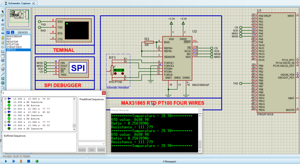
- finally make the circuit below and start the simulation.

That’s all!
If you have any questions or suggestions don’t hesitate to leave a comment below

3 comments
[…] In terms of temperature range, RTDs cover a much wider range (commonly –200°C to +850°C) than thermistors, which have nonlinear (exponential) characteristics. While RTDs are usually available in standardized curves, thermistor curves vary depending on the manufacturer. Thermistors detect changes in temperature much faster than RTDs, delivering quicker feedback. If you want to know more about RTDs, you can find projects in this [link]. […]
Hi
Hi there! Thanks for visiting my blog. Let me know if you have any questions or if there’s something specific you’d like to learn about