
This article covers STM32 KS0108 LCD integration using Proteus simulation, demonstrating how to connect the KS0108 display to STM32 via SPI.
Things used in this project
Software apps and online services:
1- STMicroelectronics STM32CubeMX
2- STMicroelectronics STM32CubeIDE
3- Proteus 8
Empowering STM32 Projects with KS0108 Graphical LCD Integration
This project aims to leverage the STM32 microcontroller’s GPIO capabilities to interface with a Graphical LCD based on the KS0108 controller. By utilizing GPIO pins for data transmission and control, we seek to create a robust and versatile display solution for various STM32-based applications. The goal is to enable seamless communication between the microcontroller and the LCD, facilitating the display of graphics and text with high resolution and clarity.
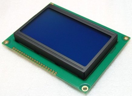
Overview of KS0108 Graphical LCDs:
Graphical LCDs utilizing the KS0108 controller are prevalent in the realm of display technology. These LCDs boast internal memory of 512 bytes, facilitating resolutions of up to 64×64 pixels. Larger displays often employ multiple controllers, with each one handling a fraction of the screen’s area. For instance, a 128×64 LCD typically incorporates two controllers, while a 128×128 display would employ four.
Each controller operates independently and is activated using two control lines: CS1 and CS2 (chip select), functioning as a 2-bit address selector for up to four ICs. Notably, these controllers lack an internal font generator, necessitating the storage of glyph pixel data by the driving device, such as a microcontroller’s Flash memory or an external memory module.
Pin Description and Functionality:
- VSS: Ground reference (0V)
- VDD: Supply voltage for the LCD (5V)
- V0: Contrast adjustment
- D/I: Selects between Data (1) or Instruction (0)
- R/W: Selects between reading (1) or writing (0) the controller
- E: Initiates data transfer upon pulse application
- DB0..7: Data bus (8-bit bus)
- CS1..2: Controller selection lines
- RES: Reset signal; resets all controllers when set to 0
- Vee: Negative voltage OUTPUT
- K and A: Backlight, typically LEDs
Sending Commands and Data to the LCD:
Sending commands or data to the LCD involves several steps, including activating the desired controller, setting the D/I line according to the type of data being sent, placing the data on the data bus, and applying a pulse to the E line. The display is divided into 8 horizontal pages and 64 vertical lines/columns.
To start this project, we will first configure the GPIO pins of the STM32 microcontroller to establish communication with the KS0108-based graphical LCD. This involves setting up the necessary GPIO pins for data transmission, control signals, and any additional functionalities required by the LCD.
STM32CubeMX Configuration:
- Open CubeMX & Create New Project Choose The Target MCU STM32F103C6 & Double-Click Its Name
- Go To The Clock Configuration & Set The System Clock To 16MHz
Configuration for the GPIO Mode:
- Configure The GPIO Pin [PA0 .. PA7] as Output Pin (D0 ,D1 , D2 , D3 , D4 , D5 , D6 , D7)
- Configure The GPIO Pin [PB8.. PB13] as Output Pin (DI ,RW , EN , CS1 , CS2 , RS )
STM32CubeIDE Configuration :
- Write The Application Layer Code
- KS0108.h & KS0108.c
- IO_Macros.h
/*
 * KS0108.h
 *
 *  Created on: May 13, 2024
 *      Author: PC-MAGHREBI
 */
#ifndef KS0108_H_INCLUDED
#define KS0108_H_INCLUDED


//----- Headers ------------//
#include "main.h"
#include "IO_Macros.h"
//--------------------------//

#define GLCD_Active_Low     0

// GLCD pins
#define GLCD_D0             GPIO_PIN_0
#define GLCD_D1             GPIO_PIN_1
#define GLCD_D2             GPIO_PIN_2
#define GLCD_D3             GPIO_PIN_3
#define GLCD_D4             GPIO_PIN_4
#define GLCD_D5             GPIO_PIN_5
#define GLCD_D6             GPIO_PIN_6
#define GLCD_D7             GPIO_PIN_7

#define GLCD_DI             GPIO_PIN_8
#define GLCD_RW             GPIO_PIN_9
#define GLCD_EN             GPIO_PIN_10
#define GLCD_CS1            GPIO_PIN_11
#define GLCD_CS2            GPIO_PIN_12
#define GLCD_RST            GPIO_PIN_13
//----- Auxiliary data ---------------------------//
#define __GLCD_Pulse_En                           1

#define __GLCD_Command_On                      0x3F
#define __GLCD_Command_Off                    0x3E
#define __GLCD_Command_Set_Address        0x40
#define __GLCD_Command_Set_Page               0xB8
#define __GLCD_Command_Display_Start    0xC0

#define __GLCD_Screen_Width              128
#define __GLCD_Screen_Height             64
#define    __GLCD_Screen_Line_Height          8
#define __GLCD_Screen_Lines                    __GLCD_Screen_Height / __GLCD_Screen_Line_Height
#define __GLCD_Screen_Chips                    2

#define __GLCD_BUSY_FLAG                      7

enum Chip_t
{
    Chip_1,
    Chip_2,
    Chip_All
};
enum ReadMode_t
{
    GLCD_Increment,
    GLCD_No_Increment
};
enum OperatingMode_t
{
    GLCD_Inverted,
    GLCD_Non_Inverted
};
enum PrintMode_t
{
    GLCD_Overwrite,
    GLCD_Merge
};
enum Color_t
{
    GLCD_White = 0x00,
    GLCD_Black = 0xFF
};

typedef struct
{
    uint8_t *Name;
    uint8_t Width;
    uint8_t Height;
    uint8_t Lines;
    enum PrintMode_t Mode;
}Font_t;

typedef struct
{
    uint8_t X;
    uint8_t Y;
    enum OperatingMode_t Mode;
    Font_t Font;
}GLCD_t;
//------------------------------------------------//

//----- Prototypes ------------------------------------------------------------//
void GLCD_SendCommand(const uint8_t Command, enum Chip_t Chip);
void GLCD_SendData(const uint8_t Data, enum Chip_t Chip);
void GLCD_Setup(void);
void GLCD_Render(void);
void GLCD_InvertMode(void);

void GLCD_Clear(void);
void GLCD_ClearLine(const uint8_t Line);
void GLCD_GotoX(const uint8_t X);
void GLCD_GotoY(const uint8_t Y);
void GLCD_GotoXY(const uint8_t X, const uint8_t Y);
void GLCD_GotoLine(const uint8_t line);
uint8_t GLCD_GetX(void);
uint8_t GLCD_GetY(void);
uint8_t GLCD_GetLine(void);

void GLCD_SetPixel(const uint8_t X, const uint8_t Y, enum Color_t Color);
void GLCD_SetPixels(uint8_t X1, uint8_t Y1, uint8_t X2, uint8_t Y2, enum Color_t Color);

void GLCD_DrawBitmap(const uint8_t *Bitmap, uint8_t Width, const uint8_t Height, enum PrintMode_t Mode);
void GLCD_DrawLine(const uint8_t X1, const uint8_t Y1, const uint8_t X2, const uint8_t Y2, enum Color_t Color);
void GLCD_DrawRectangle(const uint8_t X1, const uint8_t Y1, const uint8_t X2, const uint8_t Y2, enum Color_t Color);
void GLCD_DrawRoundRectangle(const uint8_t X1, const uint8_t Y1, const uint8_t X2, const uint8_t Y2, const uint8_t Radius, enum Color_t Color);
void GLCD_DrawTriangle(const uint8_t X1, const uint8_t Y1, const uint8_t X2, const uint8_t Y2, const uint8_t X3, const uint8_t Y3, enum Color_t Color);
void GLCD_DrawCircle(const uint8_t CenterX, const uint8_t CenterY, uint8_t Radius, enum Color_t Color);

void GLCD_FillScreen(enum Color_t Color);
void GLCD_FillRectangle(const uint8_t X1, const uint8_t Y1, const uint8_t X2, const uint8_t Y2, enum Color_t Color);
void GLCD_FillRoundRectangle(const uint8_t X1, const uint8_t Y1, const uint8_t X2, const uint8_t Y2, const uint8_t Radius, enum Color_t Color);
void GLCD_FillTriangle(uint8_t X1, uint8_t Y1, uint8_t X2, uint8_t Y2, uint8_t X3, uint8_t Y3, enum Color_t Color);
void GLCD_FillCircle(const uint8_t CenterX, const uint8_t CenterY, const uint8_t Radius, enum Color_t Color);

void GLCD_InvertScreen(void);
void GLCD_InvertRect(uint8_t X1, uint8_t Y1, uint8_t X2, uint8_t Y2);

void GLCD_SetFont(const uint8_t *Name, const uint8_t Width, const uint8_t Height, enum PrintMode_t Mode);
uint8_t GLCD_GetWidthChar(const char Character);
uint16_t GLCD_GetWidthString(const char *Text);
uint16_t GLCD_GetWidthString_P(const char *Text);
void GLCD_PrintChar(char Character);
void GLCD_PrintString(const char *Text);
void GLCD_PrintString_P(const char *Text);
void GLCD_PrintInteger(const int32_t Value);
void GLCD_PrintDouble(double Value, const uint32_t Tens);
//-----------------------------------------------------------------------------//
#endif
/*
* KS0108.c
*
* Created on: May 13, 2024
* Author: PC-MAGHREBI
*/
#include "KS0108.h"
// Delay in milliseconds
void _delay_ms(uint32_t ms) {
HAL_Delay(ms);
}
// Delay in microseconds
void _delay_us(uint32_t us) {
volatile uint32_t delay = us * (SystemCoreClock / 1000000) / 5; // Adjust the divisor to fit your system
while (delay--);
}
//----- Auxiliary data ------//
uint8_t __GLCD_Buffer[__GLCD_Screen_Width][__GLCD_Screen_Lines];
GLCD_t __GLCD;
#define __GLCD_XtoChip(X) ((X < (__GLCD_Screen_Width / __GLCD_Screen_Chips)) ? Chip_1 : Chip_2)
#define __GLCD_Min(X, Y) ((X < Y) ? X : Y)
#define __GLCD_AbsDiff(X, Y) ((X > Y) ? (X - Y) : (Y - X))
#define __GLCD_Swap(X, Y) do { typeof(X) t = X; X = Y; Y = t; } while (0)
//---------------------------//
//----- Prototypes ----------------------------//
static void GLCD_Send(const uint8_t Data);
static void GLCD_WaitBusy(enum Chip_t Chip);
static void GLCD_BufferWrite(const uint8_t X, const uint8_t Y, const uint8_t Data);
static uint8_t GLCD_BufferRead(const uint8_t X, const uint8_t Y);
static void GLCD_SelectChip(enum Chip_t Chip);
static void __GLCD_GotoX(const uint8_t X);
static void __GLCD_GotoY(const uint8_t Y);
static void GLCD_DrawHLine(uint8_t X1, uint8_t X2, const uint8_t Y, enum Color_t Color);
static void GLCD_DrawVLine(uint8_t Y1, uint8_t Y2, const uint8_t X, enum Color_t Color);
static void Int2bcd(int32_t Value, char BCD[]);
static inline void Pulse_En(void);
//---------------------------------------------//
//----- Functions -------------//
void GLCD_SendCommand(const uint8_t Command, enum Chip_t Chip)
{
//Check if busy
if (Chip != Chip_All)
{
GLCD_WaitBusy(Chip);
}
else
{
GLCD_WaitBusy(Chip_1);
GLCD_WaitBusy(Chip_2);
}
GLCD_SelectChip(Chip);
DigitalWrite(GPIOB,GLCD_DI, Low); //RS = 0
DigitalWrite(GPIOB,GLCD_RW, Low); //RW = 0
//Send data
GLCD_Send(Command);
}
void GLCD_SendData(const uint8_t Data, enum Chip_t Chip)
{
//Check if busy
if (Chip != Chip_All)
{
GLCD_WaitBusy(Chip);
}
else
{
GLCD_WaitBusy(Chip_1);
GLCD_WaitBusy(Chip_2);
}
GLCD_SelectChip(Chip);
DigitalWrite(GPIOB,GLCD_DI, High); //RS = 1
DigitalWrite(GPIOB,GLCD_RW, Low); //RW = 0
//Send data
GLCD_Send(__GLCD.Mode == GLCD_Non_Inverted ? Data : ~Data);
__GLCD.X++;
if (__GLCD.X == (__GLCD_Screen_Width / __GLCD_Screen_Chips))
__GLCD_GotoX(__GLCD.X);
else if (__GLCD.X >= __GLCD_Screen_Width)
__GLCD.X = __GLCD_Screen_Width - 1;
}
void GLCD_Setup(void)
{
//Setup pins
PinMode(GPIOA,GLCD_D0, Output); //GLCD pins = Outputs
PinMode(GPIOA,GLCD_D1, Output);
PinMode(GPIOA,GLCD_D2, Output);
PinMode(GPIOA,GLCD_D3, Output);
PinMode(GPIOA,GLCD_D4, Output);
PinMode(GPIOA,GLCD_D5, Output);
PinMode(GPIOA,GLCD_D6, Output);
PinMode(GPIOA,GLCD_D7, Output);
PinMode(GPIOB,GLCD_CS1, Output);
PinMode(GPIOB,GLCD_CS2, Output);
PinMode(GPIOB,GLCD_DI, Output);
PinMode(GPIOB,GLCD_EN, Output);
PinMode(GPIOB,GLCD_RW, Output);
PinMode(GPIOB,GLCD_RST, Output);
DigitalWrite(GPIOB,GLCD_DI, Low); //GLCD pins = 0
DigitalWrite(GPIOB,GLCD_RW, Low);
DigitalWrite(GPIOB,GLCD_EN, Low);
DigitalWrite(GPIOB,GLCD_RST, Low); //!RST
_delay_ms(5);
DigitalWrite(GPIOB,GLCD_RST, High);
_delay_ms(50);
//Initialize chips
GLCD_SendCommand(__GLCD_Command_On, Chip_All);
GLCD_SendCommand(__GLCD_Command_Display_Start, Chip_All);
//Go to 0,0
GLCD_GotoXY(0, 0);
//Reset GLCD structure
__GLCD.Mode = GLCD_Non_Inverted;
__GLCD.X = __GLCD.Y = __GLCD.Font.Width = __GLCD.Font.Height = __GLCD.Font.Lines = 0;
}
void GLCD_Render(void)
{
uint8_t i, j;
for (j = 0 ; j < __GLCD_Screen_Height ; j += __GLCD_Screen_Line_Height)
{
__GLCD_GotoX(0);
__GLCD_GotoY(j);
for (i = 0 ; i < __GLCD_Screen_Width ; i++)
GLCD_SendData(GLCD_BufferRead(i, __GLCD.Y), __GLCD_XtoChip(i));
}
}
void GLCD_InvertMode(void)
{
if (__GLCD.Mode == GLCD_Inverted)
__GLCD.Mode = GLCD_Non_Inverted;
else
__GLCD.Mode = GLCD_Inverted;
}
void GLCD_Clear(void)
{
GLCD_FillScreen(__GLCD.Mode == GLCD_Non_Inverted ? GLCD_White : GLCD_Black);
}
void GLCD_ClearLine(const uint8_t Line)
{
if (Line < __GLCD_Screen_Lines)
{
uint8_t i, color;
i = 0;
color = __GLCD.Mode == GLCD_Non_Inverted ? GLCD_White : GLCD_Black;
GLCD_GotoXY(0, Line * __GLCD_Screen_Line_Height);
for (i = 0 ; i < __GLCD_Screen_Width ; i++)
GLCD_BufferWrite(i, __GLCD.Y, color);
}
}
void GLCD_GotoX(const uint8_t X)
{
if (X < __GLCD_Screen_Width)
__GLCD.X = X;
}
void GLCD_GotoY(const uint8_t Y)
{
if (__GLCD.Y < __GLCD_Screen_Height)
__GLCD.Y = Y;
}
void GLCD_GotoXY(const uint8_t X, const uint8_t Y)
{
GLCD_GotoX(X);
GLCD_GotoY(Y);
}
void GLCD_GotoLine(const uint8_t Line)
{
if (Line < __GLCD_Screen_Lines)
__GLCD.Y = Line * __GLCD_Screen_Line_Height;
}
uint8_t GLCD_GetX(void)
{
return __GLCD.X;
}
uint8_t GLCD_GetY(void)
{
return __GLCD.Y;
}
uint8_t GLCD_GetLine(void)
{
return (__GLCD.Y / __GLCD_Screen_Line_Height);
}
void GLCD_SetPixel(const uint8_t X, const uint8_t Y, enum Color_t Color)
{
uint8_t data = 0;
//Goto to point
GLCD_GotoXY(X, Y);
//Read data
data = GLCD_BufferRead(__GLCD.X, __GLCD.Y);
//Set pixel
if (Color == GLCD_Black)
BitSet(data, Y % 8);
else
BitClear(data, Y % 8);
//Sent data
GLCD_BufferWrite(__GLCD.X, __GLCD.Y, data);
}
void GLCD_SetPixels(const uint8_t X1, uint8_t Y1, const uint8_t X2, const uint8_t Y2, enum Color_t Color)
{
if ((X1 < __GLCD_Screen_Width) && (X2 < __GLCD_Screen_Width) &&
(Y1 < __GLCD_Screen_Height) && (Y2 < __GLCD_Screen_Height))
{
uint8_t height, width, offset, mask, h, i, data;
height = Y2 - Y1 + 1;
width = X2 - X1 + 1;
offset = Y1 % __GLCD_Screen_Line_Height;
Y1 -= offset;
mask = 0xFF;
data = 0;
//Calculate mask for top fractioned region
if (height <(__GLCD_Screen_Line_Height - offset))
{
mask >>=(__GLCD_Screen_Line_Height - height);
h = height;
}
else
h = __GLCD_Screen_Line_Height - offset;
mask <<= offset;
//Draw fractional rows at the top of the region
GLCD_GotoXY(X1, Y1);
for (i = 0 ; i < width ; i++)
{
//Read
data = GLCD_BufferRead(__GLCD.X, __GLCD.Y);
//Mask
data = ((Color == GLCD_Black) ? (data | mask) : (data & ~mask));
//Write
GLCD_BufferWrite(__GLCD.X++, __GLCD.Y, data);
}
//Full rows
while ((h + __GLCD_Screen_Line_Height) <= height)
{
h += __GLCD_Screen_Line_Height;
Y1 += __GLCD_Screen_Line_Height;
GLCD_GotoXY(X1, Y1);
for (i = 0 ; i < width ; i++)
GLCD_BufferWrite(__GLCD.X++, __GLCD.Y, Color);
}
//Fractional rows at the bottom of the region
if (h < height)
{
mask = ~(0xFF << (height - h));
GLCD_GotoXY(X1, Y1 + __GLCD_Screen_Line_Height);
for (i = 0 ; i < width ; i++)
{
//Read
data = GLCD_BufferRead(__GLCD.X, __GLCD.Y);
//Mask
data = ((Color == GLCD_Black) ? (data | mask) : (data & ~mask));
//Write
GLCD_BufferWrite(__GLCD.X++, __GLCD.Y, data);
}
}
}
}
void GLCD_DrawBitmap(const uint8_t *Bitmap, uint8_t Width, const uint8_t Height, enum PrintMode_t Mode)
{
uint16_t lines, bmpRead, bmpReadPrev;
uint8_t x, y, y2, i, j, overflow, data, dataPrev;
lines = bmpRead = bmpReadPrev = x = y = i = j = overflow = data = dataPrev = 0;
//#1 - Save current position
x = __GLCD.X;
y = y2 = __GLCD.Y;
//#2 - Read width - First two bytes
data = __GLCD.X + Width; //"data" is used temporarily
//If character exceed screen bounds, reduce
if (data >= __GLCD_Screen_Width)
Width -= data - __GLCD_Screen_Width;
//#3 - Read height - Second two bytes - Convert to lines
lines = (Height + __GLCD_Screen_Line_Height - 1) / __GLCD_Screen_Line_Height; //lines = Ceiling(A/B) = (A+B-1)/B
data = __GLCD.Y / __GLCD_Screen_Line_Height + lines; //"data" is used temporarily
//If bitmap exceed screen bounds, reduce
if (data > __GLCD_Screen_Lines)
lines -= data - __GLCD_Screen_Lines;
//#4 - Calculate overflowing bits
overflow = __GLCD.Y % __GLCD_Screen_Line_Height;
//#5 - Print the character
//Scan the lines needed
for (j = 0 ; j < lines ; j++)
{
//Go to the start of the line
GLCD_GotoXY(x, y);
//Update the indices for reading the line
bmpRead = j * Width;
bmpReadPrev = bmpRead - Width; //Previous = 4 + (j - 1) * width = Current - width
//Scan bytes of selected line
for (i = 0 ; i < Width ; i++)
{
//Read byte
data = pgm_read_byte(&(Bitmap[bmpRead++]));
//Shift byte
data <<= overflow;
//Merge byte with previous one
if (j > 0)
{
dataPrev = pgm_read_byte(&(Bitmap[bmpReadPrev++]));
dataPrev >>= __GLCD_Screen_Line_Height - overflow;
data |= dataPrev;
}
//Edit byte depending on the mode
if (Mode == GLCD_Merge)
data |= GLCD_BufferRead(__GLCD.X, __GLCD.Y);
//Send byte
GLCD_BufferWrite(__GLCD.X++, __GLCD.Y, data);
}
//Send an empty column of 1px in the end'
if (__GLCD.Font.Mode == GLCD_Overwrite)
data = GLCD_White;
else
data = GLCD_BufferRead(__GLCD.X, __GLCD.Y);
GLCD_BufferWrite(__GLCD.X, __GLCD.Y, data);
//Increase line counter
y += __GLCD_Screen_Line_Height;
}
//#6 - Update last line, if needed
if (lines > 1)
{
//Go to the start of the line
GLCD_GotoXY(x, y);
//Update the index for reading the last printed line
bmpReadPrev = (j - 1) * Width;
//Scan bytes of selected line
for (i = 0 ; i < Width ; i++)
{
//Read byte
data = GLCD_BufferRead(__GLCD.X, __GLCD.Y);
//Merge byte with previous one
dataPrev = pgm_read_byte(&(Bitmap[bmpReadPrev++]));
dataPrev >>= __GLCD_Screen_Line_Height - overflow;
data |= dataPrev;
//Edit byte depending on the mode
if (Mode == GLCD_Merge)
data |= GLCD_BufferRead(__GLCD.X, __GLCD.Y);
//Send byte
GLCD_BufferWrite(__GLCD.X++, __GLCD.Y, data);
}
//Send an empty column of 1px in the end
if (__GLCD.Font.Mode == GLCD_Overwrite)
data = GLCD_White;
else if (__GLCD.Font.Mode == GLCD_Merge)
data = GLCD_BufferRead(__GLCD.X, __GLCD.Y);
else
data = ~GLCD_BufferRead(__GLCD.X, __GLCD.Y);
GLCD_BufferWrite(__GLCD.X++, __GLCD.Y,data);
}
//Go to the upper-right corner of the printed bitmap
GLCD_GotoXY(GLCD_GetX(), y2);
}
void GLCD_DrawLine(uint8_t X1, uint8_t Y1, uint8_t X2, uint8_t Y2, enum Color_t Color)
{
if ((X1 < __GLCD_Screen_Width) && (X2 < __GLCD_Screen_Width) &&
(Y1 < __GLCD_Screen_Height) && (Y2 < __GLCD_Screen_Height))
{
if (X1 == X2)
GLCD_DrawVLine(Y1, Y2, X1, Color);
else if (Y1 == Y2)
GLCD_DrawHLine(X1, X2, Y1, Color);
else
{
uint8_t deltax, deltay, x, y, slope;
int8_t error, ystep;
slope = ((__GLCD_AbsDiff(Y1, Y2) > __GLCD_AbsDiff(X1,X2)) ? 1 : 0);
if (slope)
{
//Swap x1, y1
__GLCD_Swap(X1, Y1);
//Swap x2, y2
__GLCD_Swap(X2, Y2);
}
if (X1 > X2)
{
//Swap x1, x2
__GLCD_Swap(X1, X2);
//Swap y1,y2
__GLCD_Swap(Y1, Y2);
}
deltax = X2 - X1;
deltay = __GLCD_AbsDiff(Y2, Y1);
error = deltax / 2;
y = Y1;
ystep = ((Y1 < Y2) ? 1 : -1);
for (x=X1 ; x<=X2 ; x++)
{
if (slope)
GLCD_SetPixel(y, x, Color);
else
GLCD_SetPixel(x, y, Color);
error -= deltay;
if (error < 0)
{
y = y + ystep;
error = error + deltax;
}
}
}
}
}
void GLCD_DrawRectangle(const uint8_t X1, const uint8_t Y1, const uint8_t X2, const uint8_t Y2, enum Color_t Color)
{
if ((X1 < __GLCD_Screen_Width) && (X2 < __GLCD_Screen_Width) &&
(Y1 < __GLCD_Screen_Height) && (Y2 < __GLCD_Screen_Height))
{
GLCD_DrawHLine(X1, X2, Y1, Color);
GLCD_DrawHLine(X1, X2, Y2, Color);
GLCD_DrawVLine(Y1, Y2, X1, Color);
GLCD_DrawVLine(Y1, Y2, X2, Color);
}
}
void GLCD_DrawRoundRectangle(const uint8_t X1, const uint8_t Y1, const uint8_t X2, const uint8_t Y2, const uint8_t Radius, enum Color_t Color)
{
if ((X1<__GLCD_Screen_Width) && (X2<__GLCD_Screen_Width) &&
(Y1<__GLCD_Screen_Height) && (Y2<__GLCD_Screen_Height))
{
int16_t tSwitch = 3 - 2 * Radius;
uint8_t width, height, x, y;
width = X2-X1;
height = Y2-Y1;
x = 0;
y = Radius;
//Draw perimeter
GLCD_DrawHLine(X1+Radius, X2-Radius, Y1, Color); //Top
GLCD_DrawHLine(X1+Radius, X2-Radius, Y2, Color); //Bottom
GLCD_DrawVLine(Y1+Radius, Y2-Radius, X1, Color); //Left
GLCD_DrawVLine(Y1+Radius, Y2-Radius, X2, Color); //Right
while (x <= y)
{
//Upper left corner
GLCD_SetPixel(X1+Radius-x, Y1+Radius-y, Color);
GLCD_SetPixel(X1+Radius-y, Y1+Radius-x, Color);
//Upper right corner
GLCD_SetPixel(X1+width-Radius+x, Y1+Radius-y, Color);
GLCD_SetPixel(X1+width-Radius+y, Y1+Radius-x, Color);
//Lower left corner
GLCD_SetPixel(X1+Radius-x, Y1+height-Radius+y, Color);
GLCD_SetPixel(X1+Radius-y, Y1+height-Radius+x, Color);
//Lower right corner
GLCD_SetPixel(X1+width-Radius+x, Y1+height-Radius+y, Color);
GLCD_SetPixel(X1+width-Radius+y, Y1+height-Radius+x, Color);
if (tSwitch < 0)
tSwitch += 4 * x + 6;
else
{
tSwitch += 4 * (x - y) + 10;
y--;
}
x++;
}
}
}
void GLCD_DrawTriangle(const uint8_t X1, const uint8_t Y1, const uint8_t X2, const uint8_t Y2, const uint8_t X3, const uint8_t Y3, enum Color_t Color)
{
if (((X1 < __GLCD_Screen_Width) && (X2 < __GLCD_Screen_Width) && (X3 < __GLCD_Screen_Width) &&
(Y1 < __GLCD_Screen_Height) && (Y2 < __GLCD_Screen_Height) && (Y3 < __GLCD_Screen_Height)))
{
GLCD_DrawLine(X1, Y1, X2, Y2, Color);
GLCD_DrawLine(X2, Y2, X3, Y3, Color);
GLCD_DrawLine(X3, Y3, X1, Y1, Color);
}
};
void GLCD_DrawCircle(const uint8_t CenterX, const uint8_t CenterY, const uint8_t Radius, enum Color_t Color)
{
if (((CenterX + Radius) < __GLCD_Screen_Width) && ((CenterY + Radius) < __GLCD_Screen_Height))
{
uint8_t x, y;
int16_t xChange, radiusError;
uint16_t yChange;
x = Radius;
y = 0;
xChange = 1 - 2 * Radius;
yChange = 1;
radiusError = 0;
while (x >= y)
{
GLCD_SetPixel(CenterX+x, CenterY+y, Color);
GLCD_SetPixel(CenterX-x, CenterY+y, Color);
GLCD_SetPixel(CenterX-x, CenterY-y, Color);
GLCD_SetPixel(CenterX+x, CenterY-y, Color);
GLCD_SetPixel(CenterX+y, CenterY+x, Color);
GLCD_SetPixel(CenterX-y, CenterY+x, Color);
GLCD_SetPixel(CenterX-y, CenterY-x, Color);
GLCD_SetPixel(CenterX+y, CenterY-x, Color);
y++;
radiusError += yChange;
yChange += 2;
if ((2 * radiusError + xChange) > 0)
{
x--;
radiusError += xChange;
xChange += 2;
}
}
}
}
void GLCD_FillScreen(enum Color_t Color)
{
uint8_t i, j;
for (j = 0 ; j < __GLCD_Screen_Height ; j += __GLCD_Screen_Line_Height)
for (i = 0 ; i < __GLCD_Screen_Width ; i++)
GLCD_BufferWrite(i, j, Color);
}
void GLCD_FillRectangle(const uint8_t X1, const uint8_t Y1, const uint8_t X2, const uint8_t Y2, enum Color_t Color)
{
GLCD_SetPixels(X1, Y1, X2, Y2, Color);
}
void GLCD_FillRoundRectangle(const uint8_t X1, const uint8_t Y1, const uint8_t X2, const uint8_t Y2, const uint8_t Radius, enum Color_t Color)
{
if ((X1 < __GLCD_Screen_Width) && (X2 < __GLCD_Screen_Width) &&
(Y1 < __GLCD_Screen_Height) && (Y2 < __GLCD_Screen_Height))
{
int16_t tSwitch = 3 - 2 * Radius;
uint8_t width, height, x, y;
width = X2 - X1;
height = Y2 - Y1;
x = 0;
y = Radius;
//Fill center block
GLCD_FillRectangle(X1+Radius, Y1, X2 - Radius, Y2, Color);
while (x <= y)
{
//Left side
GLCD_DrawLine(
X1 + Radius - x, Y1 + Radius - y, //Upper left corner upper half
X1 + Radius - x, Y1 + height - Radius + y, //Lower left corner lower half
Color);
GLCD_DrawLine(
X1 + Radius - y, Y1 + Radius - x, //Upper left corner lower half
X1 + Radius - y, Y1 + height - Radius + x, //Lower left corner upper half
Color);
//Right side
GLCD_DrawLine(
X1 + width - Radius + x, Y1 + Radius - y, //Upper right corner upper half
X1 + width - Radius + x, Y1 + height - Radius + y, //Lower right corner lower half
Color);
GLCD_DrawLine(
X1 + width - Radius + y, Y1 + Radius - x, //Upper right corner lower half
X1 + width - Radius + y, Y1 + height - Radius + x, //Lower right corner upper half
Color);
if (tSwitch < 0)
{
tSwitch += 4 * x +6;
}
else
{
tSwitch += 4 * (x - y) + 10;
y--;
}
x++;
}
}
}
void GLCD_FillTriangle(uint8_t X1, uint8_t Y1, uint8_t X2, uint8_t y2, uint8_t X3, uint8_t Y3, enum Color_t Color)
{
if (((X1 < __GLCD_Screen_Width) && (X2 < __GLCD_Screen_Width) && (X3 < __GLCD_Screen_Width) &&
(Y1 < __GLCD_Screen_Height) && (y2 < __GLCD_Screen_Height) && (Y3 < __GLCD_Screen_Height)))
{
uint8_t sl, sx1, sx2;
double m1, m2, m3;
sl = sx1 = sx2 = m1 = m2 = m3 = 0;
if (y2 > Y3)
{
__GLCD_Swap(X2, X3);
__GLCD_Swap(y2, Y3);
}
if (Y1 > y2)
{
__GLCD_Swap(X1, X2);
__GLCD_Swap(Y1, y2);
}
m1 = (double)(X1 - X2) / (Y1 - y2);
m2 = (double)(X2 - X3) / (y2 - Y3);
m3 = (double)(X3 - X1) / (Y3 - Y1);
for(sl = Y1 ; sl <= y2 ; sl++)
{
sx1= m1 * (sl - Y1) + X1;
sx2= m3 * (sl - Y1) + X1;
if (sx1> sx2)
__GLCD_Swap(sx1, sx2);
GLCD_DrawLine(sx1, sl, sx2, sl, Color);
}
for (sl = y2 ; sl <= Y3 ; sl++)
{
sx1= m2 * (sl - Y3) + X3;
sx2= m3 * (sl - Y1) + X1;
if (sx1 > sx2)
__GLCD_Swap(sx1, sx2);
GLCD_DrawLine(sx1, sl, sx2, sl, Color);
}
}
}
void GLCD_FillCircle(const uint8_t CenterX, const uint8_t CenterY, const uint8_t Radius, enum Color_t Color)
{
if (((CenterX + Radius) < __GLCD_Screen_Width) &&
((CenterY + Radius) < __GLCD_Screen_Height))
{
int8_t f, ddF_x, ddF_y;
uint8_t x, y;
f = 1 - Radius;
ddF_x = 1;
ddF_y = -2 * Radius;
x = 0;
y = Radius;
//Fill in the center between the two halves
GLCD_DrawLine(CenterX, CenterY - Radius, CenterX, CenterY + Radius, Color);
while(x < y)
{
//ddF_x = 2 * x + 1;
//ddF_y = -2 * y;
//f = x*x + y*y - radius*radius + 2*x - y + 1;
if (f >= 0)
{
y--;
ddF_y += 2;
f += ddF_y;
}
x++;
ddF_x += 2;
f += ddF_x;
//Now draw vertical lines between the points on the circle rather than
//draw the points of the circle. This draws lines between the
//perimeter points on the upper and lower quadrants of the 2 halves of the circle.
GLCD_DrawVLine(CenterY + y, CenterY - y, CenterX + x, Color);
GLCD_DrawVLine(CenterY + y, CenterY - y, CenterX - x, Color);
GLCD_DrawVLine(CenterY + x, CenterY - x, CenterX + y, Color);
GLCD_DrawVLine(CenterY + x, CenterY - x, CenterX - y, Color);
}
}
}
void GLCD_InvertRect(uint8_t X1, uint8_t Y1, uint8_t X2, uint8_t Y2)
{
uint8_t width, height, offset, mask, h, i, data;
width = X2 - X1 + 1;
height = Y2 - Y1 + 1;
offset = Y1 % __GLCD_Screen_Line_Height;
Y1 -= offset;
mask = 0xFF;
data = 0;
//Calculate mask for top fractioned region
if (height < (__GLCD_Screen_Line_Height - offset))
{
mask >>= (__GLCD_Screen_Line_Height - height);
h = height;
}
else
h = __GLCD_Screen_Line_Height - offset;
mask <<= offset;
//Draw fractional rows at the top of the region
GLCD_GotoXY(X1, Y1);
for (i = 0 ; i < width ; i++)
{
data = GLCD_BufferRead(__GLCD.X, __GLCD.Y);
data = ((~data) & mask) | (data & (~mask));
GLCD_BufferWrite(__GLCD.X++, __GLCD.Y, data);
}
//Full rows
while ((h + __GLCD_Screen_Line_Height) <= height)
{
h += __GLCD_Screen_Line_Height;
Y1 += __GLCD_Screen_Line_Height;
GLCD_GotoXY(X1, Y1);
for (i=0 ; i < width ; i++)
{
data = ~GLCD_BufferRead(__GLCD.X, __GLCD.Y);
GLCD_BufferWrite(__GLCD.X++, __GLCD.Y, data);
}
}
//Fractional rows at the bottom of the region
if (h < height)
{
mask = ~(0xFF<<(height - h));
GLCD_GotoXY(X1, (Y1 + __GLCD_Screen_Line_Height));
for (i = 0 ; i < width ; i++)
{
data = GLCD_BufferRead(__GLCD.X, __GLCD.Y);
data = ((~data) & mask) | (data & (~mask));
GLCD_BufferWrite(__GLCD.X++, __GLCD.Y, data);
}
}
}
void GLCD_SetFont(const uint8_t *Name, const uint8_t Width, const uint8_t Height, enum PrintMode_t Mode)
{
if ((Width < __GLCD_Screen_Width) && (Height < __GLCD_Screen_Height) && ((Mode == GLCD_Overwrite) || (Mode == GLCD_Merge)))
{
//Change font pointer to new font
__GLCD.Font.Name = (uint8_t *)(Name);
//Update font's size
__GLCD.Font.Width = Width;
__GLCD.Font.Height = Height;
//Update lines required for a character to be fully displayed
__GLCD.Font.Lines = (Height - 1) / __GLCD_Screen_Line_Height + 1;
//Update blending mode
__GLCD.Font.Mode = Mode;
}
}
uint8_t GLCD_GetWidthChar(const char Character)
{
return (pgm_read_byte(&(__GLCD.Font.Name[(Character - 32) * (__GLCD.Font.Width * __GLCD.Font.Lines + 1)])));
}
uint16_t GLCD_GetWidthString(const char *Text)
{
uint16_t width = 0;
while (*Text)
width += GLCD_GetWidthChar(*Text++);
return width;
}
uint16_t GLCD_GetWidthString_P(const char *Text)
{
uint16_t width = 0;
char r = pgm_read_byte(Text++);
while (r)
{
width += GLCD_GetWidthChar(r);
r = pgm_read_byte(Text++);
}
return width;
}
void GLCD_PrintChar(char Character)
{
uint16_t fontStart, fontRead, fontReadPrev;
uint8_t x, y, y2, i, j, width, lines, overflow, data, dataPrev;
fontStart = fontRead = fontReadPrev = x = y = y2 = i = j = width = lines = overflow = data = dataPrev = 0;
//#1 - Save current position
x = __GLCD.X;
y = y2 = __GLCD.Y;
//#2 - Remove leading empty characters
Character -= 32; //32 is the ASCII of the first printable character
//#3 - Find the start of the character in the font array
fontStart = Character * (__GLCD.Font.Width * __GLCD.Font.Lines + 1); //+1 due to first byte of each array line being the width
//#4 - Update width - First byte of each line is the width of the character
width = pgm_read_byte(&(__GLCD.Font.Name[fontStart++]));
data = __GLCD.X + width; //"data" is used temporarily
//If character exceed screen bounds, reduce
if (data >= __GLCD_Screen_Width)
width -= data-__GLCD_Screen_Width;
//#5 - Update lines
lines = __GLCD.Font.Lines;
data = __GLCD.Y / __GLCD_Screen_Line_Height + lines; //"data" is used temporarily
//If character exceed screen bounds, reduce
if (data > __GLCD_Screen_Lines)
lines -= data - __GLCD_Screen_Lines;
//#6 - Calculate overflowing bits
overflow = __GLCD.Y % __GLCD_Screen_Line_Height;
//#7 - Print the character
//Scan the lines needed
for (j = 0 ; j < lines ; j++)
{
//Go to the start of the line
GLCD_GotoXY(x, y);
//Update the indices for reading the line
fontRead = fontStart + j;
fontReadPrev = fontRead - 1;
//Scan bytes of selected line
for (i = 0 ; i < width ; i++)
{
//Read byte
data = pgm_read_byte(&(__GLCD.Font.Name[fontRead]));
//Shift byte
data <<= overflow;
//Merge byte with previous one
if (j > 0)
{
dataPrev = pgm_read_byte(&(__GLCD.Font.Name[fontReadPrev]));
dataPrev >>= __GLCD_Screen_Line_Height - overflow;
data |= dataPrev;
fontReadPrev += __GLCD.Font.Lines;
}
//Edit byte depending on the mode
if (__GLCD.Font.Mode == GLCD_Merge)
data |= GLCD_BufferRead(__GLCD.X, __GLCD.Y);
//Send byte
GLCD_BufferWrite(__GLCD.X++, __GLCD.Y, data);
//Increase index
fontRead += __GLCD.Font.Lines;
}
//Send an empty column of 1px in the end
if (__GLCD.Font.Mode == GLCD_Overwrite)
data = GLCD_White;
else
data = GLCD_BufferRead(__GLCD.X, __GLCD.Y);
GLCD_BufferWrite(__GLCD.X, __GLCD.Y, data);
//Increase line counter
y += __GLCD_Screen_Line_Height;
}
//#8 - Update last line, if needed
if (lines > 1)
{
//Go to the start of the line
GLCD_GotoXY(x, y);
//Update the index for reading the last printed line
fontReadPrev = fontStart + j - 1;
//Scan bytes of selected line
for (i = 0 ; i < width ; i++)
{
//Read byte
data = GLCD_BufferRead(__GLCD.X, __GLCD.Y);
//Merge byte with previous one
dataPrev = pgm_read_byte(&(__GLCD.Font.Name[fontReadPrev]));
dataPrev >>= __GLCD_Screen_Line_Height - overflow;
data |= dataPrev;
//Edit byte depending on the mode
if (__GLCD.Font.Mode == GLCD_Merge)
data |= GLCD_BufferRead(__GLCD.X, __GLCD.Y);
//Send byte
GLCD_BufferWrite(__GLCD.X, __GLCD.Y, data);
//Increase index
fontReadPrev += __GLCD.Font.Lines;
}
//Send an empty column of 1px in the end
if (__GLCD.Font.Mode == GLCD_Overwrite)
data = GLCD_White;
else if (__GLCD.Font.Mode == GLCD_Merge)
data = GLCD_BufferRead(__GLCD.X, __GLCD.Y);
else
data = ~GLCD_BufferRead(__GLCD.X, __GLCD.Y);
GLCD_BufferWrite(__GLCD.X++, __GLCD.Y,data);
}
//Move cursor to the end of the printed character
GLCD_GotoXY(x + width + 1, y2);
}
void GLCD_PrintString(const char *Text)
{
while(*Text)
{
if ((__GLCD.X + __GLCD.Font.Width) >= __GLCD_Screen_Width)
break;
GLCD_PrintChar(*Text++);
}
}
void GLCD_PrintString_P(const char *Text)
{
char r = pgm_read_byte(Text++);
while(r)
{
if ((__GLCD.X + __GLCD.Font.Width) >= __GLCD_Screen_Width)
break;
GLCD_PrintChar(r);
r = pgm_read_byte(Text++);
}
}
void GLCD_PrintInteger(const int32_t Value)
{
if (Value == 0)
{
GLCD_PrintChar('0');
}
else if ((Value > INT32_MIN) && (Value <= INT32_MAX))
{
//int32_max + sign + null = 12 bytes
char bcd[12] = { '\0' };
//Convert integer to array
Int2bcd(Value, bcd);
//Print from first non-zero digit
GLCD_PrintString(bcd);
}
}
void GLCD_PrintDouble(double Value, const uint32_t Tens)
{
if (Value == 0)
{
//Print characters individually so no string is stored in RAM
GLCD_PrintChar('0');
GLCD_PrintChar('.');
GLCD_PrintChar('0');
}
else if ((Value >= (-2147483647)) && (Value < 2147483648))
{
//Print sign
if (Value<0)
{
Value = -Value;
GLCD_PrintChar('-');
}
//Print integer part
GLCD_PrintInteger(Value);
//Print dot
GLCD_PrintChar('.');
//Print decimal part
GLCD_PrintInteger((Value - (uint32_t)(Value)) * Tens);
}
}
static void GLCD_Send(const uint8_t Data)
{
//Send nibble
DigitalWrite(GPIOA,GLCD_D0, BitCheck(Data, 0));
DigitalWrite(GPIOA,GLCD_D1, BitCheck(Data, 1));
DigitalWrite(GPIOA,GLCD_D2, BitCheck(Data, 2));
DigitalWrite(GPIOA,GLCD_D3, BitCheck(Data, 3));
DigitalWrite(GPIOA,GLCD_D4, BitCheck(Data, 4));
DigitalWrite(GPIOA,GLCD_D5, BitCheck(Data, 5));
DigitalWrite(GPIOA,GLCD_D6, BitCheck(Data, 6));
DigitalWrite(GPIOA,GLCD_D7, BitCheck(Data, 7));
Pulse_En();
}
static void GLCD_WaitBusy(enum Chip_t Chip)
{
uint8_t status = 0;
GLCD_SelectChip(Chip);
//Busy pin = Input
PinMode(GPIOA,GLCD_D7, Input);
DigitalWrite(GPIOB,GLCD_DI, Low);
DigitalWrite(GPIOB,GLCD_RW, High);
DigitalWrite(GPIOB,GLCD_EN, Low);
_delay_us(__GLCD_Pulse_En);
//Send Enable pulse and wait till busy flag goes Low
do
{
DigitalWrite(GPIOB,GLCD_EN, High);
_delay_us(__GLCD_Pulse_En);
status = DigitalRead(GPIOA,GLCD_D7) << 7;
DigitalWrite(GPIOB,GLCD_EN, Low);
_delay_us(__GLCD_Pulse_En<<3);
}
while(BitCheck(status, __GLCD_BUSY_FLAG));
DigitalWrite(GPIOB,GLCD_RW, Low);
//Busy pin = Output
PinMode(GPIOA,GLCD_D7, Output);
}
static void GLCD_BufferWrite(const uint8_t X, const uint8_t Y, const uint8_t Data)
{
//a>>3 = a/8
__GLCD_Buffer[X][Y>>3] = Data;
}
static uint8_t GLCD_BufferRead(const uint8_t X, const uint8_t Y)
{
//a>>3 = a/8
return (__GLCD_Buffer[X][Y>>3]);
}
static void GLCD_SelectChip(enum Chip_t Chip)
{
uint8_t on, off;
#if (GLCD_ACTIVE_LOW != 0)
on = 0;
off = 1;
#else
on = 1;
off = 0;
#endif
if(Chip == Chip_1)
{
DigitalWrite(GPIOB,GLCD_CS2, off);
DigitalWrite(GPIOB,GLCD_CS1, on);
}
else if (Chip == Chip_2)
{
DigitalWrite(GPIOB,GLCD_CS1, off);
DigitalWrite(GPIOB,GLCD_CS2, on);
}
else
{
DigitalWrite(GPIOB,GLCD_CS1, on);
DigitalWrite(GPIOB,GLCD_CS2, on);
}
}
static void __GLCD_GotoX(const uint8_t X)
{
if (X < __GLCD_Screen_Width)
{
uint8_t chip, cmd;
//Update command
chip = __GLCD_XtoChip(X);
cmd = ((chip == Chip_1) ? (__GLCD_Command_Set_Address | X) : (__GLCD_Command_Set_Address | (X - __GLCD_Screen_Width / __GLCD_Screen_Chips)));
//Update tracker
__GLCD.X = X;
//Send command
GLCD_SendCommand(cmd, chip);
}
}
static void __GLCD_GotoY(const uint8_t Y)
{
if (Y < __GLCD_Screen_Height)
{
uint8_t cmd;
//Update command
cmd = __GLCD_Command_Set_Page | (Y / __GLCD_Screen_Line_Height);
//Update tracker
__GLCD.Y = Y;
//Send command
GLCD_SendCommand(cmd, Chip_All);
}
}
static inline void GLCD_DrawHLine(uint8_t X1, uint8_t X2, const uint8_t Y, enum Color_t Color)
{
if (X1 > X2)
__GLCD_Swap(X1, X2);
while (X1 <= X2)
{
GLCD_SetPixel(X1, Y, Color);
X1++;
}
}
static inline void GLCD_DrawVLine(uint8_t Y1, uint8_t Y2, const uint8_t X, enum Color_t Color)
{
if (Y1 > Y2)
__GLCD_Swap(Y1, Y2);
GLCD_SetPixels(X, Y1, X, Y2, Color);
}
static inline void Pulse_En(void)
{
DigitalWrite(GPIOB,GLCD_EN, High);
_delay_us(__GLCD_Pulse_En);
DigitalWrite(GPIOB,GLCD_EN, Low);
_delay_us(__GLCD_Pulse_En);
}
static void Int2bcd(int32_t Value, char BCD[])
{
uint8_t isNegative = 0;
BCD[0] = BCD[1] = BCD[2] =
BCD[3] = BCD[4] = BCD[5] =
BCD[6] = BCD[7] = BCD[8] =
BCD[9] = BCD[10] = '0';
if (Value < 0)
{
isNegative = 1;
Value = -Value;
}
while (Value > 1000000000)
{
Value -= 1000000000;
BCD[1]++;
}
while (Value >= 100000000)
{
Value -= 100000000;
BCD[2]++;
}
while (Value >= 10000000)
{
Value -= 10000000;
BCD[3]++;
}
while (Value >= 1000000)
{
Value -= 1000000;
BCD[4]++;
}
while (Value >= 100000)
{
Value -= 100000;
BCD[5]++;
}
while (Value >= 10000)
{
Value -= 10000;
BCD[6]++;
}
while (Value >= 1000)
{
Value -= 1000;
BCD[7]++;
}
while (Value >= 100)
{
Value -= 100;
BCD[8]++;
}
while (Value >= 10)
{
Value -= 10;
BCD[9]++;
}
while (Value >= 1)
{
Value -= 1;
BCD[10]++;
}
uint8_t i = 0;
//Find first non zero digit
while (BCD[i] == '0')
i++;
//Add sign
if (isNegative)
{
i--;
BCD[i] = '-';
}
//Shift array
uint8_t end = 10 - i;
uint8_t offset = i;
i = 0;
while (i <= end)
{
BCD[i] = BCD[i + offset];
i++;
}
BCD[i] = '\0';
}
//-----------------------------//
/*
 * IO_Macros.h
 *
 *  Created on: May 13, 2024
 *      Author: PC-MAGHREBI
 */
#ifndef IO_MACROS_H_INCLUDED
#define IO_MACROS_H_INCLUDED

#include "main.h"

// Define GPIO port and pin macros for STM32
#define PORTA GPIOA
#define PORTB GPIOB
#define PORTC GPIOC
// Add more ports as needed...

#define PinMode(port, pin, mode) \
    do { \
        GPIO_InitTypeDef GPIO_InitStruct; \
        GPIO_InitStruct.Pin = pin; \
        GPIO_InitStruct.Mode = mode; \
        GPIO_InitStruct.Pull = GPIO_NOPULL; \
        GPIO_InitStruct.Speed = GPIO_SPEED_FREQ_LOW; \
        HAL_GPIO_Init(port, &GPIO_InitStruct); \
    } while(0)

#define DigitalRead(port, pin) HAL_GPIO_ReadPin(port, pin)
#define DigitalWrite(port, pin, value) HAL_GPIO_WritePin(port, pin, value ? GPIO_PIN_SET : GPIO_PIN_RESET)
#define DigitalLevelToggle(pin) HAL_GPIO_TogglePin(pin)

#define BitSet(x, y) ((x) |= (1U << (y)))
#define BitClear(x, y) ((x) &= ~(1U << (y)))
#define BitToggle(x, y) ((x) ^= (1U << (y)))
#define BitCheck(x, y) (((x) & (1U << (y))) != 0)

#define Input GPIO_MODE_INPUT
#define Output GPIO_MODE_OUTPUT_PP
#define Low GPIO_PIN_RESET
#define High GPIO_PIN_SET
#define False 0
#define True 1
#define pgm_read_byte(address) (*(const unsigned char *)(address))


//------------------
#endif
- Fonts11x13.h
- Fonts27x28.h
- main.c
/*
 * Fonts11x13.h
 *
 *  Created on: May 13, 2024
 *      Author: PC-MAGHREBI
 */

#ifndef INC_FONTS11X13_H_
#define INC_FONTS11X13_H_

//GLCD FontSize : 11 x 13

const uint8_t Font_11x13[]  =
{
        0x06, 0x00, 0x00, 0x00, 0x00, 0x00, 0x00, 0x00, 0x00, 0x00, 0x00, 0x00, 0x00, 0x00, 0x00, 0x00, 0x00, 0x00, 0x00, 0x00, 0x00, 0x00, 0x00,  // Code for char
        0x02, 0x00, 0x00, 0x7E, 0x03, 0x00, 0x00, 0x00, 0x00, 0x00, 0x00, 0x00, 0x00, 0x00, 0x00, 0x00, 0x00, 0x00, 0x00, 0x00, 0x00, 0x00, 0x00,  // Code for char !
        0x04, 0x00, 0x00, 0x0F, 0x00, 0x00, 0x00, 0x0F, 0x00, 0x00, 0x00, 0x00, 0x00, 0x00, 0x00, 0x00, 0x00, 0x00, 0x00, 0x00, 0x00, 0x00, 0x00,  // Code for char "
        0x08, 0x00, 0x00, 0x40, 0x00, 0x48, 0x03, 0xF8, 0x00, 0x4E, 0x03, 0xF8, 0x00, 0x4E, 0x00, 0x08, 0x00, 0x00, 0x00, 0x00, 0x00, 0x00, 0x00,  // Code for char #
        0x06, 0x18, 0x02, 0x24, 0x02, 0xFF, 0x0F, 0x44, 0x02, 0x44, 0x02, 0x84, 0x01, 0x00, 0x00, 0x00, 0x00, 0x00, 0x00, 0x00, 0x00, 0x00, 0x00,  // Code for char $
        0x0B, 0x00, 0x00, 0x1C, 0x00, 0x22, 0x00, 0x22, 0x02, 0x9C, 0x01, 0x60, 0x00, 0x10, 0x00, 0xCC, 0x01, 0x22, 0x02, 0x20, 0x02, 0xC0, 0x01,  // Code for char %
        0x08, 0xCC, 0x01, 0x32, 0x02, 0x22, 0x02, 0x22, 0x02, 0x52, 0x02, 0x8C, 0x01, 0xE0, 0x01, 0x00, 0x02, 0x00, 0x00, 0x00, 0x00, 0x00, 0x00,  // Code for char &
        0x02, 0x00, 0x00, 0x0F, 0x00, 0x00, 0x00, 0x00, 0x00, 0x00, 0x00, 0x00, 0x00, 0x00, 0x00, 0x00, 0x00, 0x00, 0x00, 0x00, 0x00, 0x00, 0x00,  // Code for char '
        0x05, 0x00, 0x00, 0xF0, 0x01, 0x0C, 0x06, 0x02, 0x08, 0x01, 0x10, 0x00, 0x00, 0x00, 0x00, 0x00, 0x00, 0x00, 0x00, 0x00, 0x00, 0x00, 0x00,  // Code for char (
        0x04, 0x01, 0x10, 0x02, 0x08, 0x0C, 0x06, 0xF0, 0x01, 0x00, 0x00, 0x00, 0x00, 0x00, 0x00, 0x00, 0x00, 0x00, 0x00, 0x00, 0x00, 0x00, 0x00,  // Code for char )
        0x06, 0x00, 0x00, 0x0A, 0x00, 0x04, 0x00, 0x1F, 0x00, 0x04, 0x00, 0x0A, 0x00, 0x00, 0x00, 0x00, 0x00, 0x00, 0x00, 0x00, 0x00, 0x00, 0x00,  // Code for char *
        0x07, 0x20, 0x00, 0x20, 0x00, 0x20, 0x00, 0xFC, 0x01, 0x20, 0x00, 0x20, 0x00, 0x20, 0x00, 0x00, 0x00, 0x00, 0x00, 0x00, 0x00, 0x00, 0x00,  // Code for char +
        0x02, 0x00, 0x08, 0x00, 0x07, 0x00, 0x00, 0x00, 0x00, 0x00, 0x00, 0x00, 0x00, 0x00, 0x00, 0x00, 0x00, 0x00, 0x00, 0x00, 0x00, 0x00, 0x00,  // Code for char ,
        0x04, 0x20, 0x00, 0x20, 0x00, 0x20, 0x00, 0x20, 0x00, 0x00, 0x00, 0x00, 0x00, 0x00, 0x00, 0x00, 0x00, 0x00, 0x00, 0x00, 0x00, 0x00, 0x00,  // Code for char -
        0x02, 0x00, 0x00, 0x00, 0x03, 0x00, 0x00, 0x00, 0x00, 0x00, 0x00, 0x00, 0x00, 0x00, 0x00, 0x00, 0x00, 0x00, 0x00, 0x00, 0x00, 0x00, 0x00,  // Code for char .
        0x05, 0x00, 0x0C, 0x80, 0x03, 0x60, 0x00, 0x1C, 0x00, 0x03, 0x00, 0x00, 0x00, 0x00, 0x00, 0x00, 0x00, 0x00, 0x00, 0x00, 0x00, 0x00, 0x00,  // Code for char /
        0x06, 0xFC, 0x01, 0x02, 0x02, 0x02, 0x02, 0x02, 0x02, 0x02, 0x02, 0xFC, 0x01, 0x00, 0x00, 0x00, 0x00, 0x00, 0x00, 0x00, 0x00, 0x00, 0x00,  // Code for char 0
        0x06, 0x00, 0x00, 0x04, 0x02, 0x04, 0x02, 0xFE, 0x03, 0x00, 0x02, 0x00, 0x02, 0x00, 0x00, 0x00, 0x00, 0x00, 0x00, 0x00, 0x00, 0x00, 0x00,  // Code for char 1
        0x06, 0x04, 0x03, 0x82, 0x02, 0x42, 0x02, 0x42, 0x02, 0x22, 0x02, 0x1C, 0x02, 0x00, 0x00, 0x00, 0x00, 0x00, 0x00, 0x00, 0x00, 0x00, 0x00,  // Code for char 2
        0x06, 0x04, 0x01, 0x02, 0x02, 0x22, 0x02, 0x22, 0x02, 0x22, 0x02, 0xDC, 0x01, 0x00, 0x00, 0x00, 0x00, 0x00, 0x00, 0x00, 0x00, 0x00, 0x00,  // Code for char 3
        0x06, 0x60, 0x00, 0x50, 0x00, 0x48, 0x00, 0x44, 0x00, 0xFE, 0x03, 0x40, 0x00, 0x00, 0x00, 0x00, 0x00, 0x00, 0x00, 0x00, 0x00, 0x00, 0x00,  // Code for char 4
        0x06, 0x1E, 0x01, 0x12, 0x02, 0x12, 0x02, 0x12, 0x02, 0x12, 0x02, 0xE2, 0x01, 0x00, 0x00, 0x00, 0x00, 0x00, 0x00, 0x00, 0x00, 0x00, 0x00,  // Code for char 5
        0x06, 0xF8, 0x01, 0x14, 0x02, 0x12, 0x02, 0x12, 0x02, 0x12, 0x02, 0xE0, 0x01, 0x00, 0x00, 0x00, 0x00, 0x00, 0x00, 0x00, 0x00, 0x00, 0x00,  // Code for char 6
        0x06, 0x02, 0x00, 0x02, 0x02, 0x82, 0x01, 0x62, 0x00, 0x1A, 0x00, 0x06, 0x00, 0x00, 0x00, 0x00, 0x00, 0x00, 0x00, 0x00, 0x00, 0x00, 0x00,  // Code for char 7
        0x06, 0xDC, 0x01, 0x22, 0x02, 0x22, 0x02, 0x22, 0x02, 0x22, 0x02, 0xDC, 0x01, 0x00, 0x00, 0x00, 0x00, 0x00, 0x00, 0x00, 0x00, 0x00, 0x00,  // Code for char 8
        0x06, 0x3C, 0x00, 0x42, 0x02, 0x42, 0x02, 0x42, 0x02, 0x42, 0x01, 0xFC, 0x00, 0x00, 0x00, 0x00, 0x00, 0x00, 0x00, 0x00, 0x00, 0x00, 0x00,  // Code for char 9
        0x03, 0x00, 0x00, 0x00, 0x00, 0x18, 0x03, 0x00, 0x00, 0x00, 0x00, 0x00, 0x00, 0x00, 0x00, 0x00, 0x00, 0x00, 0x00, 0x00, 0x00, 0x00, 0x00,  // Code for char :
        0x03, 0x00, 0x00, 0x00, 0x08, 0x18, 0x07, 0x00, 0x00, 0x00, 0x00, 0x00, 0x00, 0x00, 0x00, 0x00, 0x00, 0x00, 0x00, 0x00, 0x00, 0x00, 0x00,  // Code for char ;
        0x08, 0x00, 0x00, 0x20, 0x00, 0x20, 0x00, 0x50, 0x00, 0x50, 0x00, 0x88, 0x00, 0x88, 0x00, 0x04, 0x01, 0x00, 0x00, 0x00, 0x00, 0x00, 0x00,  // Code for char <
        0x08, 0x00, 0x00, 0x90, 0x00, 0x90, 0x00, 0x90, 0x00, 0x90, 0x00, 0x90, 0x00, 0x90, 0x00, 0x90, 0x00, 0x00, 0x00, 0x00, 0x00, 0x00, 0x00,  // Code for char =
        0x08, 0x00, 0x00, 0x04, 0x01, 0x88, 0x00, 0x88, 0x00, 0x50, 0x00, 0x50, 0x00, 0x20, 0x00, 0x20, 0x00, 0x00, 0x00, 0x00, 0x00, 0x00, 0x00,  // Code for char >
        0x05, 0x04, 0x00, 0x42, 0x03, 0x22, 0x00, 0x12, 0x00, 0x0C, 0x00, 0x00, 0x00, 0x00, 0x00, 0x00, 0x00, 0x00, 0x00, 0x00, 0x00, 0x00, 0x00,  // Code for char ?
        0x0B, 0xF0, 0x00, 0x0C, 0x03, 0x04, 0x02, 0xF2, 0x04, 0x0A, 0x05, 0x0A, 0x05, 0x0A, 0x05, 0xFA, 0x05, 0x04, 0x01, 0x0C, 0x01, 0xF0, 0x00,  // Code for char @
        0x07, 0x00, 0x03, 0xE0, 0x00, 0x98, 0x00, 0x86, 0x00, 0x98, 0x00, 0xE0, 0x00, 0x00, 0x03, 0x00, 0x00, 0x00, 0x00, 0x00, 0x00, 0x00, 0x00,  // Code for char A
        0x06, 0xFE, 0x03, 0x22, 0x02, 0x22, 0x02, 0x22, 0x02, 0x3C, 0x02, 0xC0, 0x01, 0x00, 0x00, 0x00, 0x00, 0x00, 0x00, 0x00, 0x00, 0x00, 0x00,  // Code for char B
        0x07, 0xF8, 0x00, 0x04, 0x01, 0x02, 0x02, 0x02, 0x02, 0x02, 0x02, 0x02, 0x02, 0x04, 0x01, 0x00, 0x00, 0x00, 0x00, 0x00, 0x00, 0x00, 0x00,  // Code for char C
        0x07, 0xFE, 0x03, 0x02, 0x02, 0x02, 0x02, 0x02, 0x02, 0x02, 0x02, 0x04, 0x01, 0xF8, 0x00, 0x00, 0x00, 0x00, 0x00, 0x00, 0x00, 0x00, 0x00,  // Code for char D
        0x06, 0xFE, 0x03, 0x22, 0x02, 0x22, 0x02, 0x22, 0x02, 0x22, 0x02, 0x22, 0x02, 0x00, 0x00, 0x00, 0x00, 0x00, 0x00, 0x00, 0x00, 0x00, 0x00,  // Code for char E
        0x06, 0xFE, 0x03, 0x22, 0x00, 0x22, 0x00, 0x22, 0x00, 0x22, 0x00, 0x22, 0x00, 0x00, 0x00, 0x00, 0x00, 0x00, 0x00, 0x00, 0x00, 0x00, 0x00,  // Code for char F
        0x07, 0xF8, 0x00, 0x04, 0x01, 0x02, 0x02, 0x02, 0x02, 0x42, 0x02, 0x42, 0x02, 0xC4, 0x03, 0x00, 0x00, 0x00, 0x00, 0x00, 0x00, 0x00, 0x00,  // Code for char G
        0x07, 0xFE, 0x03, 0x20, 0x00, 0x20, 0x00, 0x20, 0x00, 0x20, 0x00, 0x20, 0x00, 0xFE, 0x03, 0x00, 0x00, 0x00, 0x00, 0x00, 0x00, 0x00, 0x00,  // Code for char H
        0x03, 0x02, 0x02, 0xFE, 0x03, 0x02, 0x02, 0x00, 0x00, 0x00, 0x00, 0x00, 0x00, 0x00, 0x00, 0x00, 0x00, 0x00, 0x00, 0x00, 0x00, 0x00, 0x00,  // Code for char I
        0x04, 0x00, 0x02, 0x02, 0x02, 0x02, 0x02, 0xFE, 0x01, 0x00, 0x00, 0x00, 0x00, 0x00, 0x00, 0x00, 0x00, 0x00, 0x00, 0x00, 0x00, 0x00, 0x00,  // Code for char J
        0x06, 0xFE, 0x03, 0x20, 0x00, 0x50, 0x00, 0x88, 0x00, 0x04, 0x01, 0x02, 0x02, 0x00, 0x00, 0x00, 0x00, 0x00, 0x00, 0x00, 0x00, 0x00, 0x00,  // Code for char K
        0x05, 0xFE, 0x03, 0x00, 0x02, 0x00, 0x02, 0x00, 0x02, 0x00, 0x02, 0x00, 0x00, 0x00, 0x00, 0x00, 0x00, 0x00, 0x00, 0x00, 0x00, 0x00, 0x00,  // Code for char L
        0x09, 0xFE, 0x03, 0x06, 0x00, 0x18, 0x00, 0x60, 0x00, 0x80, 0x01, 0x60, 0x00, 0x18, 0x00, 0x06, 0x00, 0xFE, 0x03, 0x00, 0x00, 0x00, 0x00,  // Code for char M
        0x07, 0xFE, 0x03, 0x06, 0x00, 0x18, 0x00, 0x20, 0x00, 0xC0, 0x00, 0x00, 0x03, 0xFE, 0x03, 0x00, 0x00, 0x00, 0x00, 0x00, 0x00, 0x00, 0x00,  // Code for char N
        0x08, 0xF8, 0x00, 0x04, 0x01, 0x02, 0x02, 0x02, 0x02, 0x02, 0x02, 0x02, 0x02, 0x04, 0x01, 0xF8, 0x00, 0x00, 0x00, 0x00, 0x00, 0x00, 0x00,  // Code for char O
        0x06, 0xFE, 0x03, 0x22, 0x00, 0x22, 0x00, 0x22, 0x00, 0x22, 0x00, 0x1C, 0x00, 0x00, 0x00, 0x00, 0x00, 0x00, 0x00, 0x00, 0x00, 0x00, 0x00,  // Code for char P
        0x08, 0xF8, 0x00, 0x04, 0x01, 0x02, 0x02, 0x02, 0x02, 0x02, 0x06, 0x02, 0x0A, 0x04, 0x09, 0xF8, 0x08, 0x00, 0x00, 0x00, 0x00, 0x00, 0x00,  // Code for char Q
        0x07, 0xFE, 0x03, 0x22, 0x00, 0x22, 0x00, 0x62, 0x00, 0xA2, 0x00, 0x1C, 0x01, 0x00, 0x02, 0x00, 0x00, 0x00, 0x00, 0x00, 0x00, 0x00, 0x00,  // Code for char R
        0x07, 0x1C, 0x01, 0x22, 0x02, 0x22, 0x02, 0x22, 0x02, 0x22, 0x02, 0x22, 0x02, 0xC4, 0x01, 0x00, 0x00, 0x00, 0x00, 0x00, 0x00, 0x00, 0x00,  // Code for char S
        0x07, 0x02, 0x00, 0x02, 0x00, 0x02, 0x00, 0xFE, 0x03, 0x02, 0x00, 0x02, 0x00, 0x02, 0x00, 0x00, 0x00, 0x00, 0x00, 0x00, 0x00, 0x00, 0x00,  // Code for char T
        0x07, 0xFE, 0x00, 0x00, 0x01, 0x00, 0x02, 0x00, 0x02, 0x00, 0x02, 0x00, 0x01, 0xFE, 0x00, 0x00, 0x00, 0x00, 0x00, 0x00, 0x00, 0x00, 0x00,  // Code for char U
        0x07, 0x0E, 0x00, 0x30, 0x00, 0xC0, 0x00, 0x00, 0x03, 0xC0, 0x00, 0x30, 0x00, 0x0E, 0x00, 0x00, 0x00, 0x00, 0x00, 0x00, 0x00, 0x00, 0x00,  // Code for char V
        0x0B, 0x1E, 0x00, 0xE0, 0x01, 0x00, 0x02, 0xC0, 0x01, 0x38, 0x00, 0x06, 0x00, 0x38, 0x00, 0xC0, 0x01, 0x00, 0x02, 0xE0, 0x01, 0x1E, 0x00,  // Code for char W
        0x07, 0x02, 0x02, 0x04, 0x01, 0xD8, 0x00, 0x20, 0x00, 0xD8, 0x00, 0x04, 0x01, 0x02, 0x02, 0x00, 0x00, 0x00, 0x00, 0x00, 0x00, 0x00, 0x00,  // Code for char X
        0x07, 0x02, 0x00, 0x0C, 0x00, 0x10, 0x00, 0xE0, 0x03, 0x10, 0x00, 0x0C, 0x00, 0x02, 0x00, 0x00, 0x00, 0x00, 0x00, 0x00, 0x00, 0x00, 0x00,  // Code for char Y
        0x06, 0x02, 0x03, 0x82, 0x02, 0x62, 0x02, 0x12, 0x02, 0x0A, 0x02, 0x06, 0x02, 0x00, 0x00, 0x00, 0x00, 0x00, 0x00, 0x00, 0x00, 0x00, 0x00,  // Code for char Z
        0x04, 0x00, 0x00, 0xFF, 0x0F, 0x01, 0x08, 0x01, 0x08, 0x00, 0x00, 0x00, 0x00, 0x00, 0x00, 0x00, 0x00, 0x00, 0x00, 0x00, 0x00, 0x00, 0x00,  // Code for char [
        0x05, 0x03, 0x00, 0x1C, 0x00, 0x60, 0x00, 0x80, 0x03, 0x00, 0x0C, 0x00, 0x00, 0x00, 0x00, 0x00, 0x00, 0x00, 0x00, 0x00, 0x00, 0x00, 0x00,  // Code for char BackSlash
        0x04, 0x00, 0x00, 0x01, 0x08, 0x01, 0x08, 0xFF, 0x0F, 0x00, 0x00, 0x00, 0x00, 0x00, 0x00, 0x00, 0x00, 0x00, 0x00, 0x00, 0x00, 0x00, 0x00,  // Code for char ]
        0x09, 0x00, 0x00, 0x10, 0x00, 0x08, 0x00, 0x04, 0x00, 0x02, 0x00, 0x02, 0x00, 0x04, 0x00, 0x08, 0x00, 0x10, 0x00, 0x00, 0x00, 0x00, 0x00,  // Code for char ^
        0x07, 0x00, 0x08, 0x00, 0x08, 0x00, 0x08, 0x00, 0x08, 0x00, 0x08, 0x00, 0x08, 0x00, 0x08, 0x00, 0x00, 0x00, 0x00, 0x00, 0x00, 0x00, 0x00,  // Code for char _
        0x05, 0x00, 0x00, 0x00, 0x00, 0x00, 0x00, 0x01, 0x00, 0x02, 0x00, 0x00, 0x00, 0x00, 0x00, 0x00, 0x00, 0x00, 0x00, 0x00, 0x00, 0x00, 0x00,  // Code for char `
        0x06, 0x80, 0x01, 0x48, 0x02, 0x48, 0x02, 0x48, 0x02, 0x48, 0x01, 0xF0, 0x03, 0x00, 0x00, 0x00, 0x00, 0x00, 0x00, 0x00, 0x00, 0x00, 0x00,  // Code for char a
        0x06, 0xFF, 0x03, 0x10, 0x02, 0x08, 0x02, 0x08, 0x02, 0x08, 0x02, 0xF0, 0x01, 0x00, 0x00, 0x00, 0x00, 0x00, 0x00, 0x00, 0x00, 0x00, 0x00,  // Code for char b
        0x05, 0xF0, 0x01, 0x08, 0x02, 0x08, 0x02, 0x08, 0x02, 0x08, 0x02, 0x00, 0x00, 0x00, 0x00, 0x00, 0x00, 0x00, 0x00, 0x00, 0x00, 0x00, 0x00,  // Code for char c
        0x06, 0xF0, 0x01, 0x08, 0x02, 0x08, 0x02, 0x08, 0x02, 0x08, 0x01, 0xFF, 0x03, 0x00, 0x00, 0x00, 0x00, 0x00, 0x00, 0x00, 0x00, 0x00, 0x00,  // Code for char d
        0x06, 0xF0, 0x01, 0x48, 0x02, 0x48, 0x02, 0x48, 0x02, 0x48, 0x02, 0x70, 0x01, 0x00, 0x00, 0x00, 0x00, 0x00, 0x00, 0x00, 0x00, 0x00, 0x00,  // Code for char e
        0x05, 0x08, 0x00, 0xFE, 0x03, 0x09, 0x00, 0x09, 0x00, 0x01, 0x00, 0x00, 0x00, 0x00, 0x00, 0x00, 0x00, 0x00, 0x00, 0x00, 0x00, 0x00, 0x00,  // Code for char f
        0x06, 0xF0, 0x01, 0x08, 0x12, 0x08, 0x12, 0x08, 0x12, 0x08, 0x11, 0xF8, 0x0F, 0x00, 0x00, 0x00, 0x00, 0x00, 0x00, 0x00, 0x00, 0x00, 0x00,  // Code for char g
        0x06, 0xFF, 0x03, 0x10, 0x00, 0x08, 0x00, 0x08, 0x00, 0x08, 0x00, 0xF0, 0x03, 0x00, 0x00, 0x00, 0x00, 0x00, 0x00, 0x00, 0x00, 0x00, 0x00,  // Code for char h
        0x02, 0x00, 0x00, 0xFA, 0x03, 0x00, 0x00, 0x00, 0x00, 0x00, 0x00, 0x00, 0x00, 0x00, 0x00, 0x00, 0x00, 0x00, 0x00, 0x00, 0x00, 0x00, 0x00,  // Code for char i
        0x03, 0x00, 0x10, 0x08, 0x10, 0xFA, 0x0F, 0x00, 0x00, 0x00, 0x00, 0x00, 0x00, 0x00, 0x00, 0x00, 0x00, 0x00, 0x00, 0x00, 0x00, 0x00, 0x00,  // Code for char j
        0x05, 0xFF, 0x03, 0x40, 0x00, 0xA0, 0x00, 0x10, 0x01, 0x08, 0x02, 0x00, 0x00, 0x00, 0x00, 0x00, 0x00, 0x00, 0x00, 0x00, 0x00, 0x00, 0x00,  // Code for char k
        0x02, 0x00, 0x00, 0xFF, 0x03, 0x00, 0x00, 0x00, 0x00, 0x00, 0x00, 0x00, 0x00, 0x00, 0x00, 0x00, 0x00, 0x00, 0x00, 0x00, 0x00, 0x00, 0x00,  // Code for char l
        0x0A, 0x00, 0x00, 0xF8, 0x03, 0x10, 0x00, 0x08, 0x00, 0x08, 0x00, 0xF0, 0x03, 0x10, 0x00, 0x08, 0x00, 0x08, 0x00, 0xF0, 0x03, 0x00, 0x00,  // Code for char m
        0x06, 0xF8, 0x03, 0x10, 0x00, 0x08, 0x00, 0x08, 0x00, 0x08, 0x00, 0xF0, 0x03, 0x00, 0x00, 0x00, 0x00, 0x00, 0x00, 0x00, 0x00, 0x00, 0x00,  // Code for char n
        0x06, 0xF0, 0x01, 0x08, 0x02, 0x08, 0x02, 0x08, 0x02, 0x08, 0x02, 0xF0, 0x01, 0x00, 0x00, 0x00, 0x00, 0x00, 0x00, 0x00, 0x00, 0x00, 0x00,  // Code for char o
        0x06, 0xF8, 0x1F, 0x10, 0x02, 0x08, 0x02, 0x08, 0x02, 0x08, 0x02, 0xF0, 0x01, 0x00, 0x00, 0x00, 0x00, 0x00, 0x00, 0x00, 0x00, 0x00, 0x00,  // Code for char p
        0x06, 0xF0, 0x01, 0x08, 0x02, 0x08, 0x02, 0x08, 0x02, 0x08, 0x01, 0xF8, 0x1F, 0x00, 0x00, 0x00, 0x00, 0x00, 0x00, 0x00, 0x00, 0x00, 0x00,  // Code for char q
        0x04, 0xF8, 0x03, 0x10, 0x00, 0x08, 0x00, 0x08, 0x00, 0x00, 0x00, 0x00, 0x00, 0x00, 0x00, 0x00, 0x00, 0x00, 0x00, 0x00, 0x00, 0x00, 0x00,  // Code for char r
        0x05, 0x30, 0x01, 0x48, 0x02, 0x48, 0x02, 0x48, 0x02, 0x90, 0x01, 0x00, 0x00, 0x00, 0x00, 0x00, 0x00, 0x00, 0x00, 0x00, 0x00, 0x00, 0x00,  // Code for char s
        0x04, 0x08, 0x00, 0xFE, 0x01, 0x08, 0x02, 0x08, 0x02, 0x00, 0x00, 0x00, 0x00, 0x00, 0x00, 0x00, 0x00, 0x00, 0x00, 0x00, 0x00, 0x00, 0x00,  // Code for char t
        0x06, 0xF8, 0x01, 0x00, 0x02, 0x00, 0x02, 0x00, 0x02, 0x00, 0x01, 0xF8, 0x03, 0x00, 0x00, 0x00, 0x00, 0x00, 0x00, 0x00, 0x00, 0x00, 0x00,  // Code for char u
        0x05, 0x18, 0x00, 0xE0, 0x00, 0x00, 0x03, 0xE0, 0x00, 0x18, 0x00, 0x00, 0x00, 0x00, 0x00, 0x00, 0x00, 0x00, 0x00, 0x00, 0x00, 0x00, 0x00,  // Code for char v
        0x09, 0x18, 0x00, 0xE0, 0x00, 0x00, 0x03, 0xE0, 0x00, 0x18, 0x00, 0xE0, 0x00, 0x00, 0x03, 0xE0, 0x00, 0x18, 0x00, 0x00, 0x00, 0x00, 0x00,  // Code for char w
        0x05, 0x08, 0x02, 0xB0, 0x01, 0x40, 0x00, 0xB0, 0x01, 0x08, 0x02, 0x00, 0x00, 0x00, 0x00, 0x00, 0x00, 0x00, 0x00, 0x00, 0x00, 0x00, 0x00,  // Code for char x
        0x05, 0x18, 0x00, 0xE0, 0x18, 0x00, 0x07, 0xE0, 0x00, 0x18, 0x00, 0x00, 0x00, 0x00, 0x00, 0x00, 0x00, 0x00, 0x00, 0x00, 0x00, 0x00, 0x00,  // Code for char y
        0x05, 0x08, 0x03, 0x88, 0x02, 0x48, 0x02, 0x28, 0x02, 0x18, 0x02, 0x00, 0x00, 0x00, 0x00, 0x00, 0x00, 0x00, 0x00, 0x00, 0x00, 0x00, 0x00,  // Code for char z
        0x05, 0x40, 0x00, 0x40, 0x00, 0xBE, 0x07, 0x01, 0x08, 0x01, 0x08, 0x00, 0x00, 0x00, 0x00, 0x00, 0x00, 0x00, 0x00, 0x00, 0x00, 0x00, 0x00,  // Code for char {
        0x03, 0x00, 0x00, 0x00, 0x00, 0xFF, 0x0F, 0x00, 0x00, 0x00, 0x00, 0x00, 0x00, 0x00, 0x00, 0x00, 0x00, 0x00, 0x00, 0x00, 0x00, 0x00, 0x00,  // Code for char |
        0x05, 0x01, 0x08, 0x01, 0x08, 0xBE, 0x07, 0x40, 0x00, 0x40, 0x00, 0x00, 0x00, 0x00, 0x00, 0x00, 0x00, 0x00, 0x00, 0x00, 0x00, 0x00, 0x00,  // Code for char }
        0x08, 0x00, 0x00, 0x60, 0x00, 0x10, 0x00, 0x10, 0x00, 0x20, 0x00, 0x40, 0x00, 0x40, 0x00, 0x30, 0x00, 0x00, 0x00, 0x00, 0x00, 0x00, 0x00,  // Code for char ~
        0x03, 0xFF, 0x03, 0x01, 0x02, 0xFF, 0x03, 0x00, 0x00, 0x00, 0x00, 0x00, 0x00, 0x00, 0x00, 0x00, 0x00, 0x00, 0x00, 0x00, 0x00, 0x00, 0x00   // Code for char
};

#endif /* INC_FONTS11X13_H_ */
/*
 * Fonts27x28.h
 *
 *  Created on: May 13, 2024
 *      Author: PC-MAGHREBI
 */

#ifndef INC_FONTS27X28_H_
#define INC_FONTS27X28_H_

const uint8_t Font_27x28[]  =
{
        0x0E, 0x00, 0x00, 0x00, 0x00, 0x00, 0x00, 0x00, 0x00, 0x00, 0x00, 0x00, 0x00, 0x00, 0x00, 0x00, 0x00, 0x00, 0x00, 0x00, 0x00, 0x00, 0x00, 0x00, 0x00, 0x00, 0x00, 0x00, 0x00, 0x00, 0x00, 0x00, 0x00, 0x00, 0x00, 0x00, 0x00, 0x00, 0x00, 0x00, 0x00, 0x00, 0x00, 0x00, 0x00, 0x00, 0x00, 0x00, 0x00, 0x00, 0x00, 0x00, 0x00, 0x00, 0x00, 0x00, 0x00, 0x00, 0x00, 0x00, 0x00, 0x00, 0x00, 0x00, 0x00, 0x00, 0x00, 0x00, 0x00, 0x00, 0x00, 0x00, 0x00, 0x00, 0x00, 0x00, 0x00, 0x00, 0x00, 0x00, 0x00, 0x00, 0x00, 0x00, 0x00, 0x00, 0x00, 0x00, 0x00, 0x00, 0x00, 0x00, 0x00, 0x00, 0x00, 0x00, 0x00, 0x00, 0x00, 0x00, 0x00, 0x00, 0x00, 0x00, 0x00, 0x00, 0x00, 0x00, 0x00,  // Code for char
        0x05, 0x00, 0x00, 0x00, 0x00, 0x00, 0x00, 0x00, 0x00, 0xFC, 0x7F, 0x0E, 0x00, 0xFC, 0x7F, 0x0F, 0x00, 0xFC, 0x7F, 0x07, 0x00, 0x00, 0x00, 0x00, 0x00, 0x00, 0x00, 0x00, 0x00, 0x00, 0x00, 0x00, 0x00, 0x00, 0x00, 0x00, 0x00, 0x00, 0x00, 0x00, 0x00, 0x00, 0x00, 0x00, 0x00, 0x00, 0x00, 0x00, 0x00, 0x00, 0x00, 0x00, 0x00, 0x00, 0x00, 0x00, 0x00, 0x00, 0x00, 0x00, 0x00, 0x00, 0x00, 0x00, 0x00, 0x00, 0x00, 0x00, 0x00, 0x00, 0x00, 0x00, 0x00, 0x00, 0x00, 0x00, 0x00, 0x00, 0x00, 0x00, 0x00, 0x00, 0x00, 0x00, 0x00, 0x00, 0x00, 0x00, 0x00, 0x00, 0x00, 0x00, 0x00, 0x00, 0x00, 0x00, 0x00, 0x00, 0x00, 0x00, 0x00, 0x00, 0x00, 0x00, 0x00, 0x00, 0x00, 0x00, 0x00,  // Code for char !
        0x09, 0x00, 0x00, 0x00, 0x00, 0x00, 0x00, 0x00, 0x00, 0xFC, 0x01, 0x00, 0x00, 0xFC, 0x01, 0x00, 0x00, 0x00, 0x00, 0x00, 0x00, 0x00, 0x00, 0x00, 0x00, 0x00, 0x00, 0x00, 0x00, 0xFC, 0x01, 0x00, 0x00, 0xFC, 0x01, 0x00, 0x00, 0x00, 0x00, 0x00, 0x00, 0x00, 0x00, 0x00, 0x00, 0x00, 0x00, 0x00, 0x00, 0x00, 0x00, 0x00, 0x00, 0x00, 0x00, 0x00, 0x00, 0x00, 0x00, 0x00, 0x00, 0x00, 0x00, 0x00, 0x00, 0x00, 0x00, 0x00, 0x00, 0x00, 0x00, 0x00, 0x00, 0x00, 0x00, 0x00, 0x00, 0x00, 0x00, 0x00, 0x00, 0x00, 0x00, 0x00, 0x00, 0x00, 0x00, 0x00, 0x00, 0x00, 0x00, 0x00, 0x00, 0x00, 0x00, 0x00, 0x00, 0x00, 0x00, 0x00, 0x00, 0x00, 0x00, 0x00, 0x00, 0x00, 0x00, 0x00, 0x00,  // Code for char "
        0x11, 0x00, 0x00, 0x00, 0x00, 0x00, 0x60, 0x00, 0x00, 0x80, 0x61, 0x00, 0x00, 0x80, 0x61, 0x0C, 0x00, 0x80, 0xE1, 0x0F, 0x00, 0x80, 0xFD, 0x0F, 0x00, 0x80, 0x7F, 0x00, 0x00, 0xF8, 0x6F, 0x00, 0x00, 0xFC, 0x61, 0x0C, 0x00, 0x8C, 0xE1, 0x0F, 0x00, 0x80, 0xFD, 0x0F, 0x00, 0x80, 0x7F, 0x00, 0x00, 0xF8, 0x6F, 0x00, 0x00, 0xFC, 0x61, 0x00, 0x00, 0x8C, 0x61, 0x00, 0x00, 0x80, 0x21, 0x00, 0x00, 0x80, 0x01, 0x00, 0x00, 0x00, 0x00, 0x00, 0x00, 0x00, 0x00, 0x00, 0x00, 0x00, 0x00, 0x00, 0x00, 0x00, 0x00, 0x00, 0x00, 0x00, 0x00, 0x00, 0x00, 0x00, 0x00, 0x00, 0x00, 0x00, 0x00, 0x00, 0x00, 0x00, 0x00, 0x00, 0x00, 0x00, 0x00, 0x00, 0x00, 0x00, 0x00, 0x00, 0x00,  // Code for char #
        0x11, 0x00, 0x00, 0x00, 0x00, 0x00, 0x83, 0x01, 0x00, 0xC0, 0xC7, 0x03, 0x00, 0xE0, 0x8F, 0x03, 0x00, 0x70, 0x0C, 0x07, 0x00, 0x30, 0x0C, 0x06, 0x00, 0x18, 0x0C, 0x06, 0x00, 0x18, 0x04, 0x06, 0x00, 0xFF, 0xFF, 0x7F, 0x00, 0xFE, 0xFF, 0x3F, 0x00, 0x18, 0x06, 0x06, 0x00, 0x18, 0x06, 0x03, 0x00, 0x18, 0x06, 0x03, 0x00, 0x38, 0x86, 0x03, 0x00, 0x70, 0xFE, 0x01, 0x00, 0x70, 0xFC, 0x00, 0x00, 0x00, 0x78, 0x00, 0x00, 0x00, 0x00, 0x00, 0x00, 0x00, 0x00, 0x00, 0x00, 0x00, 0x00, 0x00, 0x00, 0x00, 0x00, 0x00, 0x00, 0x00, 0x00, 0x00, 0x00, 0x00, 0x00, 0x00, 0x00, 0x00, 0x00, 0x00, 0x00, 0x00, 0x00, 0x00, 0x00, 0x00, 0x00, 0x00, 0x00, 0x00, 0x00, 0x00, 0x00,  // Code for char $
        0x15, 0x00, 0x00, 0x00, 0x00, 0xE0, 0x00, 0x00, 0x00, 0xF0, 0x01, 0x00, 0x00, 0xF8, 0x03, 0x00, 0x00, 0x1C, 0x03, 0x04, 0x00, 0x0C, 0x03, 0x0E, 0x00, 0x8C, 0x83, 0x0F, 0x00, 0xFC, 0xC1, 0x03, 0x00, 0xF8, 0xF0, 0x00, 0x00, 0x70, 0x7C, 0x00, 0x00, 0x00, 0x1E, 0x00, 0x00, 0x80, 0x07, 0x03, 0x00, 0xE0, 0x83, 0x07, 0x00, 0xF0, 0xC0, 0x0F, 0x00, 0x3C, 0xC0, 0x0C, 0x00, 0x1C, 0x60, 0x0C, 0x00, 0x08, 0x60, 0x0C, 0x00, 0x00, 0x60, 0x06, 0x00, 0x00, 0xE0, 0x07, 0x00, 0x00, 0xC0, 0x03, 0x00, 0x00, 0x80, 0x01, 0x00, 0x00, 0x00, 0x00, 0x00, 0x00, 0x00, 0x00, 0x00, 0x00, 0x00, 0x00, 0x00, 0x00, 0x00, 0x00, 0x00, 0x00, 0x00, 0x00, 0x00, 0x00, 0x00, 0x00, 0x00,  // Code for char %
        0x16, 0x00, 0x00, 0x00, 0x00, 0x00, 0xE0, 0x03, 0x00, 0x00, 0xF0, 0x07, 0x00, 0x00, 0xF8, 0x07, 0x00, 0x70, 0x1C, 0x0E, 0x00, 0xF8, 0x0E, 0x0C, 0x00, 0xF8, 0x0F, 0x0C, 0x00, 0xDC, 0x07, 0x0C, 0x00, 0x8C, 0x07, 0x0C, 0x00, 0x0C, 0x0F, 0x0C, 0x00, 0x0C, 0x1F, 0x06, 0x00, 0x8C, 0x1F, 0x06, 0x00, 0xCC, 0x39, 0x07, 0x00, 0xF8, 0x71, 0x03, 0x00, 0xF8, 0xF0, 0x03, 0x00, 0x70, 0xE0, 0x01, 0x00, 0x00, 0xE0, 0x01, 0x00, 0x00, 0xF8, 0x03, 0x00, 0x00, 0x3C, 0x07, 0x00, 0x00, 0x18, 0x0E, 0x00, 0x00, 0x00, 0x0E, 0x00, 0x00, 0x00, 0x07, 0x00, 0x00, 0x00, 0x00, 0x00, 0x00, 0x00, 0x00, 0x00, 0x00, 0x00, 0x00, 0x00, 0x00, 0x00, 0x00, 0x00, 0x00, 0x00, 0x00, 0x00,  // Code for char &
        0x04, 0x00, 0x00, 0x00, 0x00, 0x00, 0x00, 0x00, 0x00, 0xFC, 0x01, 0x00, 0x00, 0xFC, 0x01, 0x00, 0x00, 0x00, 0x00, 0x00, 0x00, 0x00, 0x00, 0x00, 0x00, 0x00, 0x00, 0x00, 0x00, 0x00, 0x00, 0x00, 0x00, 0x00, 0x00, 0x00, 0x00, 0x00, 0x00, 0x00, 0x00, 0x00, 0x00, 0x00, 0x00, 0x00, 0x00, 0x00, 0x00, 0x00, 0x00, 0x00, 0x00, 0x00, 0x00, 0x00, 0x00, 0x00, 0x00, 0x00, 0x00, 0x00, 0x00, 0x00, 0x00, 0x00, 0x00, 0x00, 0x00, 0x00, 0x00, 0x00, 0x00, 0x00, 0x00, 0x00, 0x00, 0x00, 0x00, 0x00, 0x00, 0x00, 0x00, 0x00, 0x00, 0x00, 0x00, 0x00, 0x00, 0x00, 0x00, 0x00, 0x00, 0x00, 0x00, 0x00, 0x00, 0x00, 0x00, 0x00, 0x00, 0x00, 0x00, 0x00, 0x00, 0x00, 0x00, 0x00, 0x00,  // Code for char '
        0x0B, 0x00, 0x00, 0x00, 0x00, 0x00, 0x00, 0x00, 0x00, 0x00, 0xFC, 0x03, 0x00, 0x00, 0xFF, 0x1F, 0x00, 0xC0, 0xFF, 0x3F, 0x00, 0xE0, 0x03, 0xFC, 0x00, 0xF0, 0x00, 0xE0, 0x01, 0x38, 0x00, 0xC0, 0x01, 0x3C, 0x00, 0x80, 0x03, 0x1C, 0x00, 0x80, 0x03, 0x08, 0x00, 0x00, 0x00, 0x00, 0x00, 0x00, 0x00, 0x00, 0x00, 0x00, 0x00, 0x00, 0x00, 0x00, 0x00, 0x00, 0x00, 0x00, 0x00, 0x00, 0x00, 0x00, 0x00, 0x00, 0x00, 0x00, 0x00, 0x00, 0x00, 0x00, 0x00, 0x00, 0x00, 0x00, 0x00, 0x00, 0x00, 0x00, 0x00, 0x00, 0x00, 0x00, 0x00, 0x00, 0x00, 0x00, 0x00, 0x00, 0x00, 0x00, 0x00, 0x00, 0x00, 0x00, 0x00, 0x00, 0x00, 0x00, 0x00, 0x00, 0x00, 0x00, 0x00, 0x00, 0x00, 0x00, 0x00,  // Code for char (
        0x0A, 0x00, 0x00, 0x00, 0x00, 0x08, 0x00, 0x00, 0x00, 0x1C, 0x00, 0x80, 0x03, 0x3C, 0x00, 0x80, 0x03, 0x38, 0x00, 0xC0, 0x01, 0xF0, 0x00, 0xF0, 0x01, 0xE0, 0x03, 0xFC, 0x00, 0xC0, 0xFF, 0x3F, 0x00, 0x00, 0xFF, 0x1F, 0x00, 0x00, 0xFC, 0x03, 0x00, 0x00, 0x00, 0x00, 0x00, 0x00, 0x00, 0x00, 0x00, 0x00, 0x00, 0x00, 0x00, 0x00, 0x00, 0x00, 0x00, 0x00, 0x00, 0x00, 0x00, 0x00, 0x00, 0x00, 0x00, 0x00, 0x00, 0x00, 0x00, 0x00, 0x00, 0x00, 0x00, 0x00, 0x00, 0x00, 0x00, 0x00, 0x00, 0x00, 0x00, 0x00, 0x00, 0x00, 0x00, 0x00, 0x00, 0x00, 0x00, 0x00, 0x00, 0x00, 0x00, 0x00, 0x00, 0x00, 0x00, 0x00, 0x00, 0x00, 0x00, 0x00, 0x00, 0x00, 0x00, 0x00, 0x00, 0x00, 0x00,  // Code for char )
        0x0A, 0x00, 0x00, 0x00, 0x00, 0xC0, 0x00, 0x00, 0x00, 0xC0, 0x00, 0x00, 0x00, 0x4C, 0x02, 0x00, 0x00, 0xD8, 0x03, 0x00, 0x00, 0xF0, 0x01, 0x00, 0x00, 0xFC, 0x00, 0x00, 0x00, 0xAC, 0x01, 0x00, 0x00, 0x30, 0x03, 0x00, 0x00, 0x30, 0x00, 0x00, 0x00, 0x00, 0x00, 0x00, 0x00, 0x00, 0x00, 0x00, 0x00, 0x00, 0x00, 0x00, 0x00, 0x00, 0x00, 0x00, 0x00, 0x00, 0x00, 0x00, 0x00, 0x00, 0x00, 0x00, 0x00, 0x00, 0x00, 0x00, 0x00, 0x00, 0x00, 0x00, 0x00, 0x00, 0x00, 0x00, 0x00, 0x00, 0x00, 0x00, 0x00, 0x00, 0x00, 0x00, 0x00, 0x00, 0x00, 0x00, 0x00, 0x00, 0x00, 0x00, 0x00, 0x00, 0x00, 0x00, 0x00, 0x00, 0x00, 0x00, 0x00, 0x00, 0x00, 0x00, 0x00, 0x00, 0x00, 0x00, 0x00,  // Code for char *
        0x0E, 0x00, 0x00, 0x00, 0x00, 0x00, 0x40, 0x00, 0x00, 0x00, 0x60, 0x00, 0x00, 0x00, 0x60, 0x00, 0x00, 0x00, 0x60, 0x00, 0x00, 0x00, 0x60, 0x00, 0x00, 0x00, 0xFF, 0x0F, 0x00, 0x00, 0xFF, 0x0F, 0x00, 0x00, 0xFF, 0x0F, 0x00, 0x00, 0x60, 0x00, 0x00, 0x00, 0x60, 0x00, 0x00, 0x00, 0x60, 0x00, 0x00, 0x00, 0x60, 0x00, 0x00, 0x00, 0x60, 0x00, 0x00, 0x00, 0x00, 0x00, 0x00, 0x00, 0x00, 0x00, 0x00, 0x00, 0x00, 0x00, 0x00, 0x00, 0x00, 0x00, 0x00, 0x00, 0x00, 0x00, 0x00, 0x00, 0x00, 0x00, 0x00, 0x00, 0x00, 0x00, 0x00, 0x00, 0x00, 0x00, 0x00, 0x00, 0x00, 0x00, 0x00, 0x00, 0x00, 0x00, 0x00, 0x00, 0x00, 0x00, 0x00, 0x00, 0x00, 0x00, 0x00, 0x00, 0x00, 0x00, 0x00,  // Code for char +
        0x05, 0x00, 0x00, 0x00, 0x00, 0x00, 0x00, 0x66, 0x00, 0x00, 0x00, 0x6F, 0x00, 0x00, 0x00, 0x3F, 0x00, 0x00, 0x00, 0x1E, 0x00, 0x00, 0x00, 0x00, 0x00, 0x00, 0x00, 0x00, 0x00, 0x00, 0x00, 0x00, 0x00, 0x00, 0x00, 0x00, 0x00, 0x00, 0x00, 0x00, 0x00, 0x00, 0x00, 0x00, 0x00, 0x00, 0x00, 0x00, 0x00, 0x00, 0x00, 0x00, 0x00, 0x00, 0x00, 0x00, 0x00, 0x00, 0x00, 0x00, 0x00, 0x00, 0x00, 0x00, 0x00, 0x00, 0x00, 0x00, 0x00, 0x00, 0x00, 0x00, 0x00, 0x00, 0x00, 0x00, 0x00, 0x00, 0x00, 0x00, 0x00, 0x00, 0x00, 0x00, 0x00, 0x00, 0x00, 0x00, 0x00, 0x00, 0x00, 0x00, 0x00, 0x00, 0x00, 0x00, 0x00, 0x00, 0x00, 0x00, 0x00, 0x00, 0x00, 0x00, 0x00, 0x00, 0x00, 0x00, 0x00,  // Code for char ,
        0x0A, 0x00, 0x00, 0x00, 0x00, 0x00, 0x30, 0x00, 0x00, 0x00, 0x70, 0x00, 0x00, 0x00, 0x30, 0x00, 0x00, 0x00, 0x30, 0x00, 0x00, 0x00, 0x30, 0x00, 0x00, 0x00, 0x30, 0x00, 0x00, 0x00, 0x30, 0x00, 0x00, 0x00, 0x30, 0x00, 0x00, 0x00, 0x30, 0x00, 0x00, 0x00, 0x00, 0x00, 0x00, 0x00, 0x00, 0x00, 0x00, 0x00, 0x00, 0x00, 0x00, 0x00, 0x00, 0x00, 0x00, 0x00, 0x00, 0x00, 0x00, 0x00, 0x00, 0x00, 0x00, 0x00, 0x00, 0x00, 0x00, 0x00, 0x00, 0x00, 0x00, 0x00, 0x00, 0x00, 0x00, 0x00, 0x00, 0x00, 0x00, 0x00, 0x00, 0x00, 0x00, 0x00, 0x00, 0x00, 0x00, 0x00, 0x00, 0x00, 0x00, 0x00, 0x00, 0x00, 0x00, 0x00, 0x00, 0x00, 0x00, 0x00, 0x00, 0x00, 0x00, 0x00, 0x00, 0x00, 0x00,  // Code for char -
        0x05, 0x00, 0x00, 0x00, 0x00, 0x00, 0x00, 0x00, 0x00, 0x00, 0x00, 0x0E, 0x00, 0x00, 0x00, 0x0F, 0x00, 0x00, 0x00, 0x07, 0x00, 0x00, 0x00, 0x00, 0x00, 0x00, 0x00, 0x00, 0x00, 0x00, 0x00, 0x00, 0x00, 0x00, 0x00, 0x00, 0x00, 0x00, 0x00, 0x00, 0x00, 0x00, 0x00, 0x00, 0x00, 0x00, 0x00, 0x00, 0x00, 0x00, 0x00, 0x00, 0x00, 0x00, 0x00, 0x00, 0x00, 0x00, 0x00, 0x00, 0x00, 0x00, 0x00, 0x00, 0x00, 0x00, 0x00, 0x00, 0x00, 0x00, 0x00, 0x00, 0x00, 0x00, 0x00, 0x00, 0x00, 0x00, 0x00, 0x00, 0x00, 0x00, 0x00, 0x00, 0x00, 0x00, 0x00, 0x00, 0x00, 0x00, 0x00, 0x00, 0x00, 0x00, 0x00, 0x00, 0x00, 0x00, 0x00, 0x00, 0x00, 0x00, 0x00, 0x00, 0x00, 0x00, 0x00, 0x00, 0x00,  // Code for char .
        0x0B, 0x00, 0x00, 0x00, 0x00, 0x00, 0x00, 0x04, 0x00, 0x00, 0x00, 0x0F, 0x00, 0x00, 0xC0, 0x0F, 0x00, 0x00, 0xF8, 0x01, 0x00, 0x00, 0x7E, 0x00, 0x00, 0x80, 0x1F, 0x00, 0x00, 0xE0, 0x07, 0x00, 0x00, 0xFC, 0x01, 0x00, 0x00, 0x7C, 0x00, 0x00, 0x00, 0x1C, 0x00, 0x00, 0x00, 0x00, 0x00, 0x00, 0x00, 0x00, 0x00, 0x00, 0x00, 0x00, 0x00, 0x00, 0x00, 0x00, 0x00, 0x00, 0x00, 0x00, 0x00, 0x00, 0x00, 0x00, 0x00, 0x00, 0x00, 0x00, 0x00, 0x00, 0x00, 0x00, 0x00, 0x00, 0x00, 0x00, 0x00, 0x00, 0x00, 0x00, 0x00, 0x00, 0x00, 0x00, 0x00, 0x00, 0x00, 0x00, 0x00, 0x00, 0x00, 0x00, 0x00, 0x00, 0x00, 0x00, 0x00, 0x00, 0x00, 0x00, 0x00, 0x00, 0x00, 0x00, 0x00, 0x00, 0x00,  // Code for char /
        0x16, 0x00, 0x00, 0x00, 0x00, 0x00, 0xF8, 0x01, 0x00, 0x00, 0xFF, 0x03, 0x00, 0x80, 0xFF, 0x07, 0x00, 0xC0, 0x03, 0x07, 0x00, 0xE0, 0x01, 0x0E, 0x00, 0x70, 0x00, 0x0C, 0x00, 0x30, 0x00, 0x0C, 0x00, 0x38, 0x00, 0x0C, 0x00, 0x18, 0x00, 0x0C, 0x00, 0x08, 0x00, 0x0C, 0x00, 0x0C, 0x00, 0x0C, 0x00, 0x0C, 0x00, 0x06, 0x00, 0x0C, 0x00, 0x06, 0x00, 0x0C, 0x00, 0x07, 0x00, 0x0C, 0x00, 0x03, 0x00, 0x1C, 0x80, 0x03, 0x00, 0x18, 0xC0, 0x01, 0x00, 0x38, 0xF0, 0x00, 0x00, 0xF0, 0x7F, 0x00, 0x00, 0xE0, 0x3F, 0x00, 0x00, 0xC0, 0x0F, 0x00, 0x00, 0x00, 0x00, 0x00, 0x00, 0x00, 0x00, 0x00, 0x00, 0x00, 0x00, 0x00, 0x00, 0x00, 0x00, 0x00, 0x00, 0x00, 0x00, 0x00, 0x00,  // Code for char 0
        0x10, 0x00, 0x00, 0x00, 0x00, 0x00, 0x00, 0x00, 0x00, 0x00, 0x00, 0x00, 0x00, 0x00, 0x00, 0x00, 0x00, 0x00, 0x01, 0x00, 0x00, 0x80, 0x03, 0x00, 0x00, 0xC0, 0x03, 0x00, 0x00, 0xC0, 0x01, 0x00, 0x00, 0xE0, 0x00, 0x00, 0x00, 0xE0, 0x00, 0x00, 0x00, 0x70, 0x00, 0x00, 0x00, 0x70, 0x00, 0x00, 0x00, 0x38, 0x00, 0x00, 0x00, 0xF8, 0xFF, 0x0F, 0x00, 0xFC, 0xFF, 0x0F, 0x00, 0xFC, 0xFF, 0x0F, 0x00, 0x00, 0x00, 0x00, 0x00, 0x00, 0x00, 0x00, 0x00, 0x00, 0x00, 0x00, 0x00, 0x00, 0x00, 0x00, 0x00, 0x00, 0x00, 0x00, 0x00, 0x00, 0x00, 0x00, 0x00, 0x00, 0x00, 0x00, 0x00, 0x00, 0x00, 0x00, 0x00, 0x00, 0x00, 0x00, 0x00, 0x00, 0x00, 0x00, 0x00, 0x00, 0x00, 0x00, 0x00,  // Code for char 1
        0x14, 0x00, 0x00, 0x00, 0x00, 0x00, 0x00, 0x00, 0x00, 0x00, 0x00, 0x00, 0x00, 0xE0, 0x00, 0x0E, 0x00, 0xE0, 0x00, 0x0F, 0x00, 0xF0, 0xC0, 0x0F, 0x00, 0x38, 0xE0, 0x0D, 0x00, 0x18, 0xE0, 0x0C, 0x00, 0x18, 0x70, 0x0C, 0x00, 0x0C, 0x30, 0x0C, 0x00, 0x0C, 0x38, 0x0C, 0x00, 0x0C, 0x38, 0x0C, 0x00, 0x0C, 0x1C, 0x0C, 0x00, 0x0C, 0x1C, 0x0C, 0x00, 0x0C, 0x0C, 0x0C, 0x00, 0x0C, 0x0E, 0x0C, 0x00, 0x18, 0x0F, 0x0C, 0x00, 0xF8, 0x07, 0x0E, 0x00, 0xF8, 0x03, 0x0F, 0x00, 0xE0, 0x01, 0x0E, 0x00, 0x00, 0x00, 0x00, 0x00, 0x00, 0x00, 0x00, 0x00, 0x00, 0x00, 0x00, 0x00, 0x00, 0x00, 0x00, 0x00, 0x00, 0x00, 0x00, 0x00, 0x00, 0x00, 0x00, 0x00, 0x00, 0x00, 0x00, 0x00,  // Code for char 2
        0x15, 0x00, 0x00, 0x00, 0x00, 0x00, 0x00, 0x00, 0x00, 0x00, 0xC0, 0x03, 0x00, 0x7C, 0xC0, 0x07, 0x00, 0x7C, 0xC0, 0x07, 0x00, 0x7C, 0x00, 0x0E, 0x00, 0x0C, 0x00, 0x0C, 0x00, 0x0C, 0x00, 0x0C, 0x00, 0x0C, 0x0E, 0x0C, 0x00, 0x0C, 0x06, 0x0C, 0x00, 0x0C, 0x07, 0x0C, 0x00, 0x0C, 0x07, 0x0C, 0x00, 0x8C, 0x03, 0x0C, 0x00, 0xCC, 0x03, 0x06, 0x00, 0xEC, 0x03, 0x06, 0x00, 0x7C, 0x03, 0x06, 0x00, 0x3C, 0x03, 0x03, 0x00, 0x1C, 0xC7, 0x03, 0x00, 0x0C, 0xFE, 0x01, 0x00, 0x00, 0xFE, 0x00, 0x00, 0x00, 0x7C, 0x00, 0x00, 0x00, 0x00, 0x00, 0x00, 0x00, 0x00, 0x00, 0x00, 0x00, 0x00, 0x00, 0x00, 0x00, 0x00, 0x00, 0x00, 0x00, 0x00, 0x00, 0x00, 0x00, 0x00, 0x00, 0x00,  // Code for char 3
        0x16, 0x00, 0xC0, 0x00, 0x00, 0x00, 0xE0, 0x00, 0x00, 0x00, 0xF0, 0x00, 0x00, 0x00, 0xF8, 0x00, 0x00, 0x00, 0xF8, 0x00, 0x00, 0x00, 0xFC, 0x00, 0x00, 0x00, 0xEE, 0x00, 0x00, 0x00, 0x67, 0x00, 0x00, 0x80, 0x63, 0x00, 0x00, 0xC0, 0x61, 0x00, 0x00, 0xE0, 0x60, 0x00, 0x00, 0x70, 0x60, 0x00, 0x00, 0x38, 0x70, 0x00, 0x00, 0xFC, 0xFF, 0x0F, 0x00, 0xFC, 0xFF, 0x0F, 0x00, 0xFC, 0xFF, 0x0F, 0x00, 0x00, 0x30, 0x00, 0x00, 0x00, 0x30, 0x00, 0x00, 0x00, 0x30, 0x00, 0x00, 0x00, 0x38, 0x00, 0x00, 0x00, 0x38, 0x00, 0x00, 0x00, 0x38, 0x00, 0x00, 0x00, 0x00, 0x00, 0x00, 0x00, 0x00, 0x00, 0x00, 0x00, 0x00, 0x00, 0x00, 0x00, 0x00, 0x00, 0x00, 0x00, 0x00, 0x00, 0x00,  // Code for char 4
        0x15, 0x00, 0x00, 0x00, 0x00, 0x00, 0x00, 0x00, 0x00, 0x00, 0x08, 0x03, 0x00, 0xF8, 0x1F, 0x07, 0x00, 0xF8, 0x1F, 0x07, 0x00, 0xF8, 0x0D, 0x0E, 0x00, 0x08, 0x0E, 0x0C, 0x00, 0x08, 0x06, 0x0C, 0x00, 0x08, 0x06, 0x0C, 0x00, 0x08, 0x02, 0x0C, 0x00, 0x08, 0x03, 0x0C, 0x00, 0x08, 0x03, 0x0C, 0x00, 0x08, 0x03, 0x0C, 0x00, 0x08, 0x03, 0x06, 0x00, 0x0C, 0x03, 0x06, 0x00, 0x0C, 0x03, 0x07, 0x00, 0x0C, 0x07, 0x03, 0x00, 0x0C, 0xC6, 0x03, 0x00, 0x0C, 0xFE, 0x01, 0x00, 0x00, 0xFC, 0x00, 0x00, 0x00, 0x78, 0x00, 0x00, 0x00, 0x00, 0x00, 0x00, 0x00, 0x00, 0x00, 0x00, 0x00, 0x00, 0x00, 0x00, 0x00, 0x00, 0x00, 0x00, 0x00, 0x00, 0x00, 0x00, 0x00, 0x00, 0x00, 0x00,  // Code for char 5
        0x16, 0x00, 0x00, 0x00, 0x00, 0x00, 0x78, 0x00, 0x00, 0x00, 0xFE, 0x03, 0x00, 0x80, 0xFF, 0x03, 0x00, 0xC0, 0xC7, 0x07, 0x00, 0xE0, 0xE1, 0x07, 0x00, 0x60, 0x70, 0x0E, 0x00, 0x70, 0x30, 0x0C, 0x00, 0x38, 0x38, 0x0C, 0x00, 0x18, 0x1C, 0x0C, 0x00, 0x18, 0x0C, 0x0C, 0x00, 0x0C, 0x0C, 0x0C, 0x00, 0x0C, 0x06, 0x0C, 0x00, 0x0C, 0x06, 0x0E, 0x00, 0x0C, 0x06, 0x06, 0x00, 0x0C, 0x06, 0x06, 0x00, 0x0C, 0x06, 0x07, 0x00, 0x0C, 0x06, 0x03, 0x00, 0x38, 0x8E, 0x03, 0x00, 0x78, 0xFC, 0x01, 0x00, 0x30, 0xFC, 0x00, 0x00, 0x00, 0x78, 0x00, 0x00, 0x00, 0x00, 0x00, 0x00, 0x00, 0x00, 0x00, 0x00, 0x00, 0x00, 0x00, 0x00, 0x00, 0x00, 0x00, 0x00, 0x00, 0x00, 0x00, 0x00,  // Code for char 6
        0x16, 0x00, 0x00, 0x00, 0x00, 0x00, 0x00, 0x00, 0x00, 0x00, 0x00, 0x00, 0x00, 0xF8, 0x01, 0x00, 0x00, 0xFC, 0x01, 0x00, 0x00, 0xFC, 0x00, 0x00, 0x00, 0x0C, 0x00, 0x00, 0x00, 0x0C, 0x00, 0x00, 0x00, 0x0C, 0x00, 0x00, 0x00, 0x0C, 0x00, 0x0E, 0x00, 0x0C, 0x80, 0x0F, 0x00, 0x0C, 0xE0, 0x07, 0x00, 0x0C, 0xF0, 0x01, 0x00, 0x0C, 0xFC, 0x00, 0x00, 0x0C, 0x3E, 0x00, 0x00, 0x8C, 0x1F, 0x00, 0x00, 0xEC, 0x07, 0x00, 0x00, 0xFC, 0x03, 0x00, 0x00, 0xFC, 0x00, 0x00, 0x00, 0x3C, 0x00, 0x00, 0x00, 0x0C, 0x00, 0x00, 0x00, 0x04, 0x00, 0x00, 0x00, 0x00, 0x00, 0x00, 0x00, 0x00, 0x00, 0x00, 0x00, 0x00, 0x00, 0x00, 0x00, 0x00, 0x00, 0x00, 0x00, 0x00, 0x00, 0x00, 0x00,  // Code for char 7
        0x16, 0x00, 0x00, 0x00, 0x00, 0x00, 0xC0, 0x01, 0x00, 0x00, 0xE0, 0x03, 0x00, 0x00, 0xF0, 0x07, 0x00, 0xC0, 0x79, 0x06, 0x00, 0xF0, 0x3B, 0x0E, 0x00, 0xF8, 0x1F, 0x0C, 0x00, 0x38, 0x0E, 0x0C, 0x00, 0x18, 0x0C, 0x0C, 0x00, 0x1C, 0x0C, 0x0C, 0x00, 0x0C, 0x06, 0x0C, 0x00, 0x0C, 0x06, 0x0C, 0x00, 0x0C, 0x06, 0x06, 0x00, 0x0C, 0x06, 0x06, 0x00, 0x0C, 0x06, 0x06, 0x00, 0x1C, 0x07, 0x03, 0x00, 0xF8, 0x07, 0x03, 0x00, 0xF8, 0x86, 0x03, 0x00, 0x70, 0xCE, 0x01, 0x00, 0x00, 0xFC, 0x00, 0x00, 0x00, 0xFC, 0x00, 0x00, 0x00, 0x38, 0x00, 0x00, 0x00, 0x00, 0x00, 0x00, 0x00, 0x00, 0x00, 0x00, 0x00, 0x00, 0x00, 0x00, 0x00, 0x00, 0x00, 0x00, 0x00, 0x00, 0x00, 0x00,  // Code for char 8
        0x16, 0x00, 0x00, 0x00, 0x00, 0x00, 0x00, 0x01, 0x00, 0x80, 0x83, 0x03, 0x00, 0xE0, 0x87, 0x07, 0x00, 0xF0, 0x0F, 0x07, 0x00, 0x70, 0x0C, 0x0E, 0x00, 0x38, 0x1C, 0x0C, 0x00, 0x18, 0x18, 0x0C, 0x00, 0x1C, 0x18, 0x0C, 0x00, 0x0C, 0x18, 0x0C, 0x00, 0x0C, 0x18, 0x0C, 0x00, 0x0C, 0x18, 0x0C, 0x00, 0x0C, 0x18, 0x04, 0x00, 0x0C, 0x0C, 0x06, 0x00, 0x0C, 0x0C, 0x06, 0x00, 0x1C, 0x0C, 0x07, 0x00, 0x18, 0x86, 0x03, 0x00, 0x38, 0xC7, 0x03, 0x00, 0xF0, 0xE3, 0x01, 0x00, 0xF0, 0xFF, 0x00, 0x00, 0xE0, 0x7F, 0x00, 0x00, 0x00, 0x1F, 0x00, 0x00, 0x00, 0x00, 0x00, 0x00, 0x00, 0x00, 0x00, 0x00, 0x00, 0x00, 0x00, 0x00, 0x00, 0x00, 0x00, 0x00, 0x00, 0x00, 0x00, 0x00,  // Code for char 9
        0x05, 0x00, 0x00, 0x00, 0x00, 0x00, 0x00, 0x00, 0x00, 0x00, 0x0C, 0x0E, 0x00, 0x00, 0x1E, 0x0F, 0x00, 0x00, 0x0C, 0x07, 0x00, 0x00, 0x00, 0x00, 0x00, 0x00, 0x00, 0x00, 0x00, 0x00, 0x00, 0x00, 0x00, 0x00, 0x00, 0x00, 0x00, 0x00, 0x00, 0x00, 0x00, 0x00, 0x00, 0x00, 0x00, 0x00, 0x00, 0x00, 0x00, 0x00, 0x00, 0x00, 0x00, 0x00, 0x00, 0x00, 0x00, 0x00, 0x00, 0x00, 0x00, 0x00, 0x00, 0x00, 0x00, 0x00, 0x00, 0x00, 0x00, 0x00, 0x00, 0x00, 0x00, 0x00, 0x00, 0x00, 0x00, 0x00, 0x00, 0x00, 0x00, 0x00, 0x00, 0x00, 0x00, 0x00, 0x00, 0x00, 0x00, 0x00, 0x00, 0x00, 0x00, 0x00, 0x00, 0x00, 0x00, 0x00, 0x00, 0x00, 0x00, 0x00, 0x00, 0x00, 0x00, 0x00, 0x00, 0x00, 0x00,  // Code for char :
        0x05, 0x00, 0x00, 0x00, 0x00, 0x00, 0x00, 0x66, 0x00, 0x00, 0x0C, 0x6F, 0x00, 0x00, 0x1E, 0x3F, 0x00, 0x00, 0x0E, 0x1E, 0x00, 0x00, 0x00, 0x00, 0x00, 0x00, 0x00, 0x00, 0x00, 0x00, 0x00, 0x00, 0x00, 0x00, 0x00, 0x00, 0x00, 0x00, 0x00, 0x00, 0x00, 0x00, 0x00, 0x00, 0x00, 0x00, 0x00, 0x00, 0x00, 0x00, 0x00, 0x00, 0x00, 0x00, 0x00, 0x00, 0x00, 0x00, 0x00, 0x00, 0x00, 0x00, 0x00, 0x00, 0x00, 0x00, 0x00, 0x00, 0x00, 0x00, 0x00, 0x00, 0x00, 0x00, 0x00, 0x00, 0x00, 0x00, 0x00, 0x00, 0x00, 0x00, 0x00, 0x00, 0x00, 0x00, 0x00, 0x00, 0x00, 0x00, 0x00, 0x00, 0x00, 0x00, 0x00, 0x00, 0x00, 0x00, 0x00, 0x00, 0x00, 0x00, 0x00, 0x00, 0x00, 0x00, 0x00, 0x00, 0x00,  // Code for char ;
        0x0D, 0x00, 0x00, 0x00, 0x00, 0x00, 0x00, 0x00, 0x00, 0x00, 0x60, 0x00, 0x00, 0x00, 0x70, 0x00, 0x00, 0x00, 0xF0, 0x00, 0x00, 0x00, 0xF8, 0x01, 0x00, 0x00, 0xD8, 0x01, 0x00, 0x00, 0x9C, 0x03, 0x00, 0x00, 0x0C, 0x03, 0x00, 0x00, 0x0E, 0x07, 0x00, 0x00, 0x07, 0x0E, 0x00, 0x00, 0x07, 0x0E, 0x00, 0x00, 0x02, 0x02, 0x00, 0x00, 0x00, 0x00, 0x00, 0x00, 0x00, 0x00, 0x00, 0x00, 0x00, 0x00, 0x00, 0x00, 0x00, 0x00, 0x00, 0x00, 0x00, 0x00, 0x00, 0x00, 0x00, 0x00, 0x00, 0x00, 0x00, 0x00, 0x00, 0x00, 0x00, 0x00, 0x00, 0x00, 0x00, 0x00, 0x00, 0x00, 0x00, 0x00, 0x00, 0x00, 0x00, 0x00, 0x00, 0x00, 0x00, 0x00, 0x00, 0x00, 0x00, 0x00, 0x00, 0x00, 0x00, 0x00, 0x00,  // Code for char <
        0x0D, 0x00, 0x00, 0x00, 0x00, 0x00, 0x8C, 0x01, 0x00, 0x00, 0x8C, 0x01, 0x00, 0x00, 0x8C, 0x01, 0x00, 0x00, 0x8C, 0x01, 0x00, 0x00, 0x8C, 0x01, 0x00, 0x00, 0x8C, 0x01, 0x00, 0x00, 0x8C, 0x01, 0x00, 0x00, 0x8C, 0x01, 0x00, 0x00, 0x8C, 0x01, 0x00, 0x00, 0x8C, 0x01, 0x00, 0x00, 0x8C, 0x01, 0x00, 0x00, 0x8C, 0x01, 0x00, 0x00, 0x00, 0x00, 0x00, 0x00, 0x00, 0x00, 0x00, 0x00, 0x00, 0x00, 0x00, 0x00, 0x00, 0x00, 0x00, 0x00, 0x00, 0x00, 0x00, 0x00, 0x00, 0x00, 0x00, 0x00, 0x00, 0x00, 0x00, 0x00, 0x00, 0x00, 0x00, 0x00, 0x00, 0x00, 0x00, 0x00, 0x00, 0x00, 0x00, 0x00, 0x00, 0x00, 0x00, 0x00, 0x00, 0x00, 0x00, 0x00, 0x00, 0x00, 0x00, 0x00, 0x00, 0x00, 0x00,  // Code for char =
        0x0D, 0x00, 0x00, 0x00, 0x00, 0x00, 0x00, 0x00, 0x00, 0x00, 0x02, 0x02, 0x00, 0x00, 0x07, 0x0E, 0x00, 0x00, 0x07, 0x0E, 0x00, 0x00, 0x0E, 0x07, 0x00, 0x00, 0x0C, 0x03, 0x00, 0x00, 0x9C, 0x03, 0x00, 0x00, 0xD8, 0x01, 0x00, 0x00, 0xF8, 0x01, 0x00, 0x00, 0xF0, 0x00, 0x00, 0x00, 0x70, 0x00, 0x00, 0x00, 0x60, 0x00, 0x00, 0x00, 0x00, 0x00, 0x00, 0x00, 0x00, 0x00, 0x00, 0x00, 0x00, 0x00, 0x00, 0x00, 0x00, 0x00, 0x00, 0x00, 0x00, 0x00, 0x00, 0x00, 0x00, 0x00, 0x00, 0x00, 0x00, 0x00, 0x00, 0x00, 0x00, 0x00, 0x00, 0x00, 0x00, 0x00, 0x00, 0x00, 0x00, 0x00, 0x00, 0x00, 0x00, 0x00, 0x00, 0x00, 0x00, 0x00, 0x00, 0x00, 0x00, 0x00, 0x00, 0x00, 0x00, 0x00, 0x00,  // Code for char >
        0x10, 0x00, 0x00, 0x00, 0x00, 0x20, 0x00, 0x00, 0x00, 0x70, 0x00, 0x00, 0x00, 0xF0, 0x00, 0x00, 0x00, 0x78, 0x70, 0x00, 0x00, 0x18, 0xF8, 0x00, 0x00, 0x18, 0xFC, 0x1C, 0x00, 0x0C, 0xDC, 0x1E, 0x00, 0x0C, 0xCE, 0x0E, 0x00, 0x0C, 0xC7, 0x00, 0x00, 0x0C, 0xF7, 0x00, 0x00, 0x8C, 0x73, 0x00, 0x00, 0xDC, 0x21, 0x00, 0x00, 0xF8, 0x01, 0x00, 0x00, 0xF8, 0x00, 0x00, 0x00, 0x70, 0x00, 0x00, 0x00, 0x00, 0x00, 0x00, 0x00, 0x00, 0x00, 0x00, 0x00, 0x00, 0x00, 0x00, 0x00, 0x00, 0x00, 0x00, 0x00, 0x00, 0x00, 0x00, 0x00, 0x00, 0x00, 0x00, 0x00, 0x00, 0x00, 0x00, 0x00, 0x00, 0x00, 0x00, 0x00, 0x00, 0x00, 0x00, 0x00, 0x00, 0x00, 0x00, 0x00, 0x00, 0x00, 0x00, 0x00,  // Code for char ?
        0x1B, 0x00, 0x00, 0x00, 0x00, 0x00, 0x80, 0x07, 0x00, 0x00, 0xE0, 0x1F, 0x00, 0x00, 0x78, 0x38, 0x00, 0x00, 0x1C, 0x30, 0x00, 0x00, 0x0E, 0x70, 0x00, 0x00, 0x06, 0x67, 0x00, 0x00, 0xC3, 0x67, 0x00, 0x80, 0xE3, 0x6F, 0x00, 0x80, 0x71, 0x6C, 0x00, 0x80, 0x39, 0x6C, 0x00, 0xC0, 0x18, 0x6C, 0x00, 0xC0, 0x0C, 0x66, 0x00, 0xC0, 0x0C, 0x36, 0x00, 0x60, 0x04, 0x33, 0x00, 0x60, 0x86, 0x3B, 0x00, 0x60, 0x86, 0x11, 0x00, 0x60, 0xC6, 0x07, 0x00, 0x60, 0xFE, 0x0F, 0x00, 0x60, 0xFE, 0x0F, 0x00, 0x60, 0x0E, 0x0C, 0x00, 0x60, 0x00, 0x0C, 0x00, 0xC0, 0x00, 0x06, 0x00, 0xC0, 0x01, 0x06, 0x00, 0x80, 0x83, 0x03, 0x00, 0x00, 0xFF, 0x01, 0x00, 0x00, 0x7C, 0x00, 0x00,  // Code for char @
        0x15, 0x00, 0x00, 0x0E, 0x00, 0x00, 0x80, 0x0F, 0x00, 0x00, 0xC0, 0x0F, 0x00, 0x00, 0xF0, 0x01, 0x00, 0x00, 0x78, 0x00, 0x00, 0x00, 0x3E, 0x00, 0x00, 0x00, 0x1F, 0x00, 0x00, 0x80, 0x1F, 0x00, 0x00, 0xE0, 0x1B, 0x00, 0x00, 0xF8, 0x18, 0x00, 0x00, 0x7C, 0x18, 0x00, 0x00, 0x7C, 0x18, 0x00, 0x00, 0xF8, 0x18, 0x00, 0x00, 0xE0, 0x1B, 0x00, 0x00, 0x80, 0x1F, 0x00, 0x00, 0x00, 0x1F, 0x00, 0x00, 0x00, 0x7C, 0x00, 0x00, 0x00, 0xF8, 0x01, 0x00, 0x00, 0xE0, 0x0F, 0x00, 0x00, 0x80, 0x0F, 0x00, 0x00, 0x00, 0x0E, 0x00, 0x00, 0x00, 0x00, 0x00, 0x00, 0x00, 0x00, 0x00, 0x00, 0x00, 0x00, 0x00, 0x00, 0x00, 0x00, 0x00, 0x00, 0x00, 0x00, 0x00, 0x00, 0x00, 0x00, 0x00,  // Code for char A
        0x15, 0x00, 0x00, 0x00, 0x00, 0x00, 0x00, 0x00, 0x00, 0xF8, 0xFF, 0x0F, 0x00, 0xFC, 0xFF, 0x0F, 0x00, 0xF8, 0xFF, 0x0F, 0x00, 0x18, 0x06, 0x0C, 0x00, 0x18, 0x06, 0x0C, 0x00, 0x18, 0x07, 0x0C, 0x00, 0x0C, 0x07, 0x04, 0x00, 0x0C, 0x03, 0x06, 0x00, 0x0C, 0x03, 0x06, 0x00, 0x8C, 0x03, 0x06, 0x00, 0x8C, 0x03, 0x07, 0x00, 0xCC, 0x03, 0x03, 0x00, 0xCC, 0x03, 0x03, 0x00, 0xFC, 0x83, 0x03, 0x00, 0x78, 0xC3, 0x01, 0x00, 0x38, 0xE7, 0x01, 0x00, 0x00, 0xFE, 0x00, 0x00, 0x00, 0x7E, 0x00, 0x00, 0x00, 0x1C, 0x00, 0x00, 0x00, 0x00, 0x00, 0x00, 0x00, 0x00, 0x00, 0x00, 0x00, 0x00, 0x00, 0x00, 0x00, 0x00, 0x00, 0x00, 0x00, 0x00, 0x00, 0x00, 0x00, 0x00, 0x00, 0x00,  // Code for char B
        0x12, 0x00, 0x00, 0x00, 0x00, 0x00, 0x7C, 0x00, 0x00, 0x00, 0xFF, 0x01, 0x00, 0xC0, 0xFF, 0x07, 0x00, 0xE0, 0x83, 0x07, 0x00, 0xF0, 0x00, 0x0E, 0x00, 0x30, 0x00, 0x0E, 0x00, 0x38, 0x00, 0x0C, 0x00, 0x18, 0x00, 0x0C, 0x00, 0x0C, 0x00, 0x0C, 0x00, 0x0C, 0x00, 0x0C, 0x00, 0x0C, 0x00, 0x0C, 0x00, 0x0C, 0x00, 0x06, 0x00, 0x0C, 0x00, 0x07, 0x00, 0x0C, 0x00, 0x07, 0x00, 0x18, 0xC0, 0x03, 0x00, 0x38, 0xC0, 0x01, 0x00, 0x38, 0xC0, 0x01, 0x00, 0x00, 0x00, 0x00, 0x00, 0x00, 0x00, 0x00, 0x00, 0x00, 0x00, 0x00, 0x00, 0x00, 0x00, 0x00, 0x00, 0x00, 0x00, 0x00, 0x00, 0x00, 0x00, 0x00, 0x00, 0x00, 0x00, 0x00, 0x00, 0x00, 0x00, 0x00, 0x00, 0x00, 0x00, 0x00, 0x00,  // Code for char C
        0x15, 0x00, 0x00, 0x00, 0x00, 0x00, 0x00, 0x00, 0x00, 0xFC, 0xFF, 0x0F, 0x00, 0xFC, 0xFF, 0x0F, 0x00, 0xFC, 0xFF, 0x0F, 0x00, 0x38, 0x00, 0x0C, 0x00, 0x18, 0x00, 0x0C, 0x00, 0x18, 0x00, 0x0C, 0x00, 0x1C, 0x00, 0x06, 0x00, 0x0C, 0x00, 0x06, 0x00, 0x0C, 0x00, 0x06, 0x00, 0x0C, 0x00, 0x07, 0x00, 0x0C, 0x00, 0x03, 0x00, 0x0C, 0x80, 0x03, 0x00, 0x0C, 0x80, 0x03, 0x00, 0x1C, 0xC0, 0x01, 0x00, 0x18, 0xE0, 0x01, 0x00, 0x78, 0xF8, 0x00, 0x00, 0xF0, 0x7F, 0x00, 0x00, 0xE0, 0x1F, 0x00, 0x00, 0xC0, 0x07, 0x00, 0x00, 0x00, 0x00, 0x00, 0x00, 0x00, 0x00, 0x00, 0x00, 0x00, 0x00, 0x00, 0x00, 0x00, 0x00, 0x00, 0x00, 0x00, 0x00, 0x00, 0x00, 0x00, 0x00, 0x00, 0x00,  // Code for char D
        0x13, 0x00, 0x00, 0x00, 0x00, 0x10, 0x00, 0x00, 0x00, 0xFC, 0xFF, 0x0F, 0x00, 0xFC, 0xFF, 0x0F, 0x00, 0xFC, 0xFF, 0x0F, 0x00, 0x18, 0x0C, 0x06, 0x00, 0x18, 0x0C, 0x06, 0x00, 0x18, 0x0C, 0x06, 0x00, 0x18, 0x0C, 0x06, 0x00, 0x18, 0x0C, 0x06, 0x00, 0x18, 0x0C, 0x06, 0x00, 0x18, 0x0C, 0x06, 0x00, 0x18, 0x0C, 0x06, 0x00, 0x18, 0x0E, 0x06, 0x00, 0x1C, 0x0E, 0x06, 0x00, 0x1C, 0x04, 0x06, 0x00, 0x1C, 0x00, 0x07, 0x00, 0x00, 0x00, 0x07, 0x00, 0x00, 0x00, 0x02, 0x00, 0x00, 0x00, 0x00, 0x00, 0x00, 0x00, 0x00, 0x00, 0x00, 0x00, 0x00, 0x00, 0x00, 0x00, 0x00, 0x00, 0x00, 0x00, 0x00, 0x00, 0x00, 0x00, 0x00, 0x00, 0x00, 0x00, 0x00, 0x00, 0x00, 0x00, 0x00, 0x00,  // Code for char E
        0x11, 0x00, 0x00, 0x00, 0x00, 0x00, 0x00, 0x00, 0x00, 0xF8, 0xFF, 0x0F, 0x00, 0xFC, 0xFF, 0x0F, 0x00, 0xFC, 0xFF, 0x0F, 0x00, 0x38, 0x1C, 0x00, 0x00, 0x38, 0x1C, 0x00, 0x00, 0x38, 0x0C, 0x00, 0x00, 0x18, 0x0C, 0x00, 0x00, 0x18, 0x0C, 0x00, 0x00, 0x18, 0x0C, 0x00, 0x00, 0x18, 0x0C, 0x00, 0x00, 0x18, 0x0E, 0x00, 0x00, 0x1C, 0x0E, 0x00, 0x00, 0x1C, 0x0E, 0x00, 0x00, 0x1C, 0x0E, 0x00, 0x00, 0x1C, 0x00, 0x00, 0x00, 0x00, 0x00, 0x00, 0x00, 0x00, 0x00, 0x00, 0x00, 0x00, 0x00, 0x00, 0x00, 0x00, 0x00, 0x00, 0x00, 0x00, 0x00, 0x00, 0x00, 0x00, 0x00, 0x00, 0x00, 0x00, 0x00, 0x00, 0x00, 0x00, 0x00, 0x00, 0x00, 0x00, 0x00, 0x00, 0x00, 0x00, 0x00, 0x00, 0x00,  // Code for char F
        0x17, 0x00, 0x00, 0x00, 0x00, 0x00, 0xF8, 0x00, 0x00, 0x00, 0xFE, 0x01, 0x00, 0x80, 0xFF, 0x03, 0x00, 0xC0, 0x87, 0x07, 0x00, 0xE0, 0x01, 0x06, 0x00, 0xE0, 0x00, 0x0E, 0x00, 0x70, 0x00, 0x0C, 0x00, 0x30, 0x00, 0x0C, 0x00, 0x38, 0x00, 0x0C, 0x00, 0x18, 0x00, 0x0C, 0x00, 0x18, 0x00, 0x0C, 0x00, 0x0C, 0x10, 0x0C, 0x00, 0x0C, 0x18, 0x06, 0x00, 0x0C, 0x18, 0x06, 0x00, 0x0C, 0x18, 0x06, 0x00, 0x0C, 0x18, 0x03, 0x00, 0x0C, 0x98, 0x03, 0x00, 0x1C, 0xCC, 0x01, 0x00, 0x18, 0xEC, 0x01, 0x00, 0x38, 0xFC, 0x00, 0x00, 0x10, 0x7C, 0x00, 0x00, 0x00, 0x1C, 0x00, 0x00, 0x00, 0x00, 0x00, 0x00, 0x00, 0x00, 0x00, 0x00, 0x00, 0x00, 0x00, 0x00, 0x00, 0x00, 0x00, 0x00,  // Code for char G
        0x14, 0x00, 0x00, 0x00, 0x00, 0x00, 0x0C, 0x00, 0x00, 0xFC, 0xFF, 0x0F, 0x00, 0xFC, 0xFF, 0x0F, 0x00, 0xFC, 0xFF, 0x0F, 0x00, 0x00, 0x0E, 0x00, 0x00, 0x00, 0x0E, 0x00, 0x00, 0x00, 0x0E, 0x00, 0x00, 0x00, 0x0E, 0x00, 0x00, 0x00, 0x0E, 0x00, 0x00, 0x00, 0x0E, 0x00, 0x00, 0x00, 0x0E, 0x00, 0x00, 0x00, 0x06, 0x00, 0x00, 0x00, 0x06, 0x00, 0x00, 0x00, 0x06, 0x00, 0x00, 0x00, 0x06, 0x00, 0x00, 0x00, 0x06, 0x00, 0x00, 0xFC, 0xFF, 0x0F, 0x00, 0xFC, 0xFF, 0x0F, 0x00, 0xFC, 0xFF, 0x0F, 0x00, 0x00, 0x00, 0x00, 0x00, 0x00, 0x00, 0x00, 0x00, 0x00, 0x00, 0x00, 0x00, 0x00, 0x00, 0x00, 0x00, 0x00, 0x00, 0x00, 0x00, 0x00, 0x00, 0x00, 0x00, 0x00, 0x00, 0x00, 0x00,  // Code for char H
        0x05, 0x00, 0x00, 0x00, 0x00, 0x00, 0x00, 0x00, 0x00, 0xFC, 0xFF, 0x0F, 0x00, 0xFC, 0xFF, 0x0F, 0x00, 0xFC, 0xFF, 0x0F, 0x00, 0x00, 0x00, 0x00, 0x00, 0x00, 0x00, 0x00, 0x00, 0x00, 0x00, 0x00, 0x00, 0x00, 0x00, 0x00, 0x00, 0x00, 0x00, 0x00, 0x00, 0x00, 0x00, 0x00, 0x00, 0x00, 0x00, 0x00, 0x00, 0x00, 0x00, 0x00, 0x00, 0x00, 0x00, 0x00, 0x00, 0x00, 0x00, 0x00, 0x00, 0x00, 0x00, 0x00, 0x00, 0x00, 0x00, 0x00, 0x00, 0x00, 0x00, 0x00, 0x00, 0x00, 0x00, 0x00, 0x00, 0x00, 0x00, 0x00, 0x00, 0x00, 0x00, 0x00, 0x00, 0x00, 0x00, 0x00, 0x00, 0x00, 0x00, 0x00, 0x00, 0x00, 0x00, 0x00, 0x00, 0x00, 0x00, 0x00, 0x00, 0x00, 0x00, 0x00, 0x00, 0x00, 0x00, 0x00, 0x00,  // Code for char I
        0x10, 0x00, 0x00, 0x00, 0x00, 0x00, 0x80, 0x03, 0x00, 0x00, 0xC0, 0x07, 0x00, 0x00, 0xC0, 0x0F, 0x00, 0x00, 0x00, 0x1C, 0x00, 0x00, 0x00, 0x18, 0x00, 0x00, 0x00, 0x18, 0x00, 0x00, 0x00, 0x18, 0x00, 0x00, 0x00, 0x18, 0x00, 0x00, 0x00, 0x18, 0x00, 0x00, 0x00, 0x1C, 0x00, 0x00, 0x00, 0x0E, 0x00, 0x00, 0x00, 0x0F, 0x00, 0xFC, 0xFF, 0x07, 0x00, 0xFC, 0xFF, 0x03, 0x00, 0xFC, 0xFF, 0x01, 0x00, 0x00, 0x00, 0x00, 0x00, 0x00, 0x00, 0x00, 0x00, 0x00, 0x00, 0x00, 0x00, 0x00, 0x00, 0x00, 0x00, 0x00, 0x00, 0x00, 0x00, 0x00, 0x00, 0x00, 0x00, 0x00, 0x00, 0x00, 0x00, 0x00, 0x00, 0x00, 0x00, 0x00, 0x00, 0x00, 0x00, 0x00, 0x00, 0x00, 0x00, 0x00, 0x00, 0x00, 0x00,  // Code for char J
        0x13, 0x00, 0x00, 0x00, 0x00, 0x00, 0x00, 0x00, 0x00, 0xFC, 0xFF, 0x0F, 0x00, 0xFC, 0xFF, 0x0F, 0x00, 0xFC, 0xFF, 0x0F, 0x00, 0x80, 0x0F, 0x00, 0x00, 0x80, 0x0F, 0x00, 0x00, 0xC0, 0x1D, 0x00, 0x00, 0xE0, 0x38, 0x00, 0x00, 0xE0, 0x78, 0x00, 0x00, 0x70, 0x70, 0x00, 0x00, 0x30, 0xE0, 0x00, 0x00, 0x38, 0xC0, 0x01, 0x00, 0x18, 0xC0, 0x03, 0x00, 0x0C, 0x80, 0x03, 0x00, 0x0C, 0x00, 0x07, 0x00, 0x00, 0x00, 0x0E, 0x00, 0x00, 0x00, 0x0E, 0x00, 0x00, 0x00, 0x04, 0x00, 0x00, 0x00, 0x00, 0x00, 0x00, 0x00, 0x00, 0x00, 0x00, 0x00, 0x00, 0x00, 0x00, 0x00, 0x00, 0x00, 0x00, 0x00, 0x00, 0x00, 0x00, 0x00, 0x00, 0x00, 0x00, 0x00, 0x00, 0x00, 0x00, 0x00, 0x00, 0x00,  // Code for char K
        0x0F, 0x00, 0x00, 0x00, 0x00, 0x00, 0x00, 0x00, 0x00, 0xFC, 0xFF, 0x0F, 0x00, 0xFC, 0xFF, 0x0F, 0x00, 0xFC, 0xFF, 0x0F, 0x00, 0x00, 0x00, 0x0E, 0x00, 0x00, 0x00, 0x0E, 0x00, 0x00, 0x00, 0x06, 0x00, 0x00, 0x00, 0x06, 0x00, 0x00, 0x00, 0x06, 0x00, 0x00, 0x00, 0x06, 0x00, 0x00, 0x00, 0x07, 0x00, 0x00, 0x00, 0x07, 0x00, 0x00, 0x00, 0x07, 0x00, 0x00, 0x00, 0x07, 0x00, 0x00, 0x00, 0x00, 0x00, 0x00, 0x00, 0x00, 0x00, 0x00, 0x00, 0x00, 0x00, 0x00, 0x00, 0x00, 0x00, 0x00, 0x00, 0x00, 0x00, 0x00, 0x00, 0x00, 0x00, 0x00, 0x00, 0x00, 0x00, 0x00, 0x00, 0x00, 0x00, 0x00, 0x00, 0x00, 0x00, 0x00, 0x00, 0x00, 0x00, 0x00, 0x00, 0x00, 0x00, 0x00, 0x00, 0x00, 0x00,  // Code for char L
        0x19, 0x00, 0x00, 0x00, 0x00, 0x00, 0x00, 0x00, 0x00, 0xF8, 0xFF, 0x0F, 0x00, 0xFC, 0xFF, 0x0F, 0x00, 0xFC, 0xFF, 0x0F, 0x00, 0xF0, 0x01, 0x00, 0x00, 0xC0, 0x03, 0x00, 0x00, 0x80, 0x0F, 0x00, 0x00, 0x00, 0x1E, 0x00, 0x00, 0x00, 0x7C, 0x00, 0x00, 0x00, 0xF8, 0x01, 0x00, 0x00, 0xE0, 0x07, 0x00, 0x00, 0x80, 0x0F, 0x00, 0x00, 0x80, 0x0F, 0x00, 0x00, 0xE0, 0x07, 0x00, 0x00, 0xF0, 0x01, 0x00, 0x00, 0xF8, 0x00, 0x00, 0x00, 0x3C, 0x00, 0x00, 0x00, 0x1E, 0x00, 0x00, 0x00, 0x0F, 0x00, 0x00, 0xC0, 0x03, 0x00, 0x00, 0xE0, 0x01, 0x00, 0x00, 0xFC, 0xFF, 0x0F, 0x00, 0xFC, 0xFF, 0x0F, 0x00, 0xFC, 0xFF, 0x0F, 0x00, 0x00, 0x00, 0x00, 0x00, 0x00, 0x00, 0x00, 0x00,  // Code for char M
        0x13, 0x00, 0x00, 0x00, 0x00, 0x00, 0x00, 0x00, 0x00, 0xFC, 0xFF, 0x0F, 0x00, 0xFC, 0xFF, 0x0F, 0x00, 0xFC, 0xFF, 0x0F, 0x00, 0xF0, 0x01, 0x00, 0x00, 0xC0, 0x03, 0x00, 0x00, 0x80, 0x07, 0x00, 0x00, 0x00, 0x0F, 0x00, 0x00, 0x00, 0x1E, 0x00, 0x00, 0x00, 0x3C, 0x00, 0x00, 0x00, 0x38, 0x00, 0x00, 0x00, 0x70, 0x00, 0x00, 0x00, 0xF0, 0x00, 0x00, 0x00, 0xE0, 0x01, 0x00, 0x00, 0xC0, 0x03, 0x00, 0xFC, 0xFF, 0x07, 0x00, 0xFC, 0xFF, 0x0F, 0x00, 0xFC, 0xFF, 0x0F, 0x00, 0x00, 0x00, 0x00, 0x00, 0x00, 0x00, 0x00, 0x00, 0x00, 0x00, 0x00, 0x00, 0x00, 0x00, 0x00, 0x00, 0x00, 0x00, 0x00, 0x00, 0x00, 0x00, 0x00, 0x00, 0x00, 0x00, 0x00, 0x00, 0x00, 0x00, 0x00, 0x00,  // Code for char N
        0x15, 0x00, 0x00, 0x00, 0x00, 0x00, 0xF8, 0x00, 0x00, 0x00, 0xFE, 0x01, 0x00, 0x80, 0xFF, 0x03, 0x00, 0xC0, 0x83, 0x07, 0x00, 0xE0, 0x01, 0x06, 0x00, 0x70, 0x00, 0x0E, 0x00, 0x30, 0x00, 0x0C, 0x00, 0x38, 0x00, 0x0C, 0x00, 0x18, 0x00, 0x0C, 0x00, 0x0C, 0x00, 0x0C, 0x00, 0x0C, 0x00, 0x0C, 0x00, 0x0C, 0x00, 0x06, 0x00, 0x0C, 0x00, 0x06, 0x00, 0x0C, 0x00, 0x07, 0x00, 0x1C, 0x00, 0x03, 0x00, 0x18, 0xC0, 0x03, 0x00, 0x78, 0xE0, 0x01, 0x00, 0xF0, 0xFF, 0x00, 0x00, 0xE0, 0x7F, 0x00, 0x00, 0x80, 0x1F, 0x00, 0x00, 0x00, 0x00, 0x00, 0x00, 0x00, 0x00, 0x00, 0x00, 0x00, 0x00, 0x00, 0x00, 0x00, 0x00, 0x00, 0x00, 0x00, 0x00, 0x00, 0x00, 0x00, 0x00, 0x00, 0x00,  // Code for char O
        0x13, 0x00, 0x00, 0x00, 0x00, 0xC0, 0x00, 0x00, 0x00, 0xFC, 0xFF, 0x0F, 0x00, 0xFC, 0xFF, 0x0F, 0x00, 0xFC, 0xFF, 0x0F, 0x00, 0x38, 0x1C, 0x00, 0x00, 0x38, 0x0C, 0x00, 0x00, 0x18, 0x0C, 0x00, 0x00, 0x18, 0x0C, 0x00, 0x00, 0x08, 0x0E, 0x00, 0x00, 0x0C, 0x0E, 0x00, 0x00, 0x0C, 0x06, 0x00, 0x00, 0x0C, 0x07, 0x00, 0x00, 0x0C, 0x03, 0x00, 0x00, 0x8C, 0x03, 0x00, 0x00, 0xCC, 0x01, 0x00, 0x00, 0xFC, 0x01, 0x00, 0x00, 0xF8, 0x00, 0x00, 0x00, 0x38, 0x00, 0x00, 0x00, 0x00, 0x00, 0x00, 0x00, 0x00, 0x00, 0x00, 0x00, 0x00, 0x00, 0x00, 0x00, 0x00, 0x00, 0x00, 0x00, 0x00, 0x00, 0x00, 0x00, 0x00, 0x00, 0x00, 0x00, 0x00, 0x00, 0x00, 0x00, 0x00, 0x00, 0x00, 0x00,  // Code for char P
        0x17, 0x00, 0x00, 0x00, 0x00, 0x00, 0xF8, 0x00, 0x00, 0x00, 0xFE, 0x03, 0x00, 0x80, 0xFF, 0x07, 0x00, 0xC0, 0x07, 0x07, 0x00, 0xE0, 0x01, 0x0E, 0x00, 0xE0, 0x00, 0x0C, 0x00, 0x70, 0x00, 0x0C, 0x00, 0x30, 0x00, 0x0C, 0x00, 0x18, 0x00, 0x0C, 0x00, 0x18, 0x00, 0x0C, 0x00, 0x0C, 0x20, 0x0C, 0x00, 0x0C, 0x70, 0x0E, 0x00, 0x0C, 0xF0, 0x06, 0x00, 0x0C, 0xE0, 0x06, 0x00, 0x0C, 0xC0, 0x07, 0x00, 0x1C, 0xC0, 0x03, 0x00, 0x1C, 0xC0, 0x07, 0x00, 0x78, 0xF0, 0x07, 0x00, 0xF0, 0xFF, 0x0E, 0x00, 0xE0, 0x3F, 0x1C, 0x00, 0xC0, 0x0F, 0x1C, 0x00, 0x00, 0x00, 0x08, 0x00, 0x00, 0x00, 0x00, 0x00, 0x00, 0x00, 0x00, 0x00, 0x00, 0x00, 0x00, 0x00, 0x00, 0x00, 0x00, 0x00,  // Code for char Q
        0x15, 0x00, 0x00, 0x00, 0x00, 0xE0, 0x00, 0x00, 0x00, 0xFC, 0xFF, 0x0F, 0x00, 0xFC, 0xFF, 0x0F, 0x00, 0xFC, 0xFF, 0x0F, 0x00, 0x38, 0x1C, 0x00, 0x00, 0x18, 0x3E, 0x00, 0x00, 0x18, 0x3E, 0x00, 0x00, 0x18, 0x76, 0x00, 0x00, 0x0C, 0x76, 0x00, 0x00, 0x0C, 0xE6, 0x00, 0x00, 0x0C, 0xE3, 0x00, 0x00, 0x0C, 0xC3, 0x00, 0x00, 0x8C, 0xC3, 0x01, 0x00, 0x8C, 0x81, 0x01, 0x00, 0xCC, 0x81, 0x03, 0x00, 0xFC, 0x00, 0x03, 0x00, 0xF8, 0x00, 0x07, 0x00, 0x38, 0x00, 0x06, 0x00, 0x00, 0x00, 0x0E, 0x00, 0x00, 0x00, 0x0E, 0x00, 0x00, 0x00, 0x00, 0x00, 0x00, 0x00, 0x00, 0x00, 0x00, 0x00, 0x00, 0x00, 0x00, 0x00, 0x00, 0x00, 0x00, 0x00, 0x00, 0x00, 0x00, 0x00, 0x00, 0x00,  // Code for char R
        0x15, 0x00, 0x00, 0x00, 0x00, 0x00, 0x07, 0x03, 0x00, 0xC0, 0x87, 0x07, 0x00, 0xE0, 0x0F, 0x07, 0x00, 0x70, 0x0C, 0x0E, 0x00, 0x30, 0x0C, 0x0C, 0x00, 0x18, 0x0C, 0x0C, 0x00, 0x18, 0x0C, 0x0C, 0x00, 0x18, 0x0C, 0x0C, 0x00, 0x0C, 0x04, 0x0C, 0x00, 0x0C, 0x04, 0x0C, 0x00, 0x0C, 0x06, 0x0E, 0x00, 0x0C, 0x06, 0x06, 0x00, 0x0C, 0x06, 0x06, 0x00, 0x0C, 0x06, 0x07, 0x00, 0x1C, 0x06, 0x07, 0x00, 0x38, 0x86, 0x03, 0x00, 0x38, 0xC6, 0x03, 0x00, 0x10, 0xFE, 0x01, 0x00, 0x00, 0xFC, 0x00, 0x00, 0x00, 0x38, 0x00, 0x00, 0x00, 0x00, 0x00, 0x00, 0x00, 0x00, 0x00, 0x00, 0x00, 0x00, 0x00, 0x00, 0x00, 0x00, 0x00, 0x00, 0x00, 0x00, 0x00, 0x00, 0x00, 0x00, 0x00, 0x00,  // Code for char S
        0x12, 0x30, 0x00, 0x00, 0x00, 0x30, 0x00, 0x00, 0x00, 0x30, 0x00, 0x00, 0x00, 0x30, 0x00, 0x00, 0x00, 0x30, 0x00, 0x00, 0x00, 0x10, 0x00, 0x00, 0x00, 0x10, 0x00, 0x00, 0x00, 0xF8, 0xFF, 0x0F, 0x00, 0xF8, 0xFF, 0x0F, 0x00, 0xF8, 0xFF, 0x0F, 0x00, 0x18, 0x00, 0x00, 0x00, 0x08, 0x00, 0x00, 0x00, 0x08, 0x00, 0x00, 0x00, 0x08, 0x00, 0x00, 0x00, 0x0C, 0x00, 0x00, 0x00, 0x0C, 0x00, 0x00, 0x00, 0x0C, 0x00, 0x00, 0x00, 0x0C, 0x00, 0x00, 0x00, 0x00, 0x00, 0x00, 0x00, 0x00, 0x00, 0x00, 0x00, 0x00, 0x00, 0x00, 0x00, 0x00, 0x00, 0x00, 0x00, 0x00, 0x00, 0x00, 0x00, 0x00, 0x00, 0x00, 0x00, 0x00, 0x00, 0x00, 0x00, 0x00, 0x00, 0x00, 0x00, 0x00, 0x00, 0x00, 0x00,  // Code for char T
        0x12, 0x00, 0x00, 0x00, 0x00, 0x00, 0x00, 0x00, 0x00, 0xFC, 0xFF, 0x03, 0x00, 0xFC, 0xFF, 0x07, 0x00, 0xF8, 0xFF, 0x07, 0x00, 0x00, 0x00, 0x0E, 0x00, 0x00, 0x00, 0x0C, 0x00, 0x00, 0x00, 0x0C, 0x00, 0x00, 0x00, 0x0C, 0x00, 0x00, 0x00, 0x0C, 0x00, 0x00, 0x00, 0x0C, 0x00, 0x00, 0x00, 0x0E, 0x00, 0x00, 0x00, 0x06, 0x00, 0x00, 0x00, 0x07, 0x00, 0x00, 0x00, 0x07, 0x00, 0xFC, 0xFF, 0x03, 0x00, 0xFC, 0xFF, 0x01, 0x00, 0xFC, 0xFF, 0x00, 0x00, 0x00, 0x00, 0x00, 0x00, 0x00, 0x00, 0x00, 0x00, 0x00, 0x00, 0x00, 0x00, 0x00, 0x00, 0x00, 0x00, 0x00, 0x00, 0x00, 0x00, 0x00, 0x00, 0x00, 0x00, 0x00, 0x00, 0x00, 0x00, 0x00, 0x00, 0x00, 0x00, 0x00, 0x00, 0x00, 0x00,  // Code for char U
        0x13, 0x00, 0x00, 0x00, 0x00, 0x3C, 0x00, 0x00, 0x00, 0xFC, 0x01, 0x00, 0x00, 0xF8, 0x07, 0x00, 0x00, 0xC0, 0x1F, 0x00, 0x00, 0x00, 0x7F, 0x00, 0x00, 0x00, 0xF8, 0x0F, 0x00, 0x00, 0xC0, 0x0F, 0x00, 0x00, 0xC0, 0x0F, 0x00, 0x00, 0xF0, 0x00, 0x00, 0x00, 0x7C, 0x00, 0x00, 0x00, 0x1E, 0x00, 0x00, 0x00, 0x0F, 0x00, 0x00, 0xC0, 0x03, 0x00, 0x00, 0xE0, 0x01, 0x00, 0x00, 0xF0, 0x00, 0x00, 0x00, 0x78, 0x00, 0x00, 0x00, 0x3C, 0x00, 0x00, 0x00, 0x18, 0x00, 0x00, 0x00, 0x00, 0x00, 0x00, 0x00, 0x00, 0x00, 0x00, 0x00, 0x00, 0x00, 0x00, 0x00, 0x00, 0x00, 0x00, 0x00, 0x00, 0x00, 0x00, 0x00, 0x00, 0x00, 0x00, 0x00, 0x00, 0x00, 0x00, 0x00, 0x00, 0x00, 0x00, 0x00,  // Code for char V
        0x1B, 0x00, 0x00, 0x00, 0x00, 0x7C, 0x00, 0x00, 0x00, 0xFC, 0x03, 0x00, 0x00, 0xFC, 0x1F, 0x00, 0x00, 0x00, 0xFF, 0x00, 0x00, 0x00, 0xF8, 0x0F, 0x00, 0x00, 0xE0, 0x0F, 0x00, 0x00, 0xC0, 0x0F, 0x00, 0x00, 0xF0, 0x01, 0x00, 0x00, 0x78, 0x00, 0x00, 0x00, 0x3E, 0x00, 0x00, 0x80, 0x0F, 0x00, 0x00, 0xF8, 0x03, 0x00, 0x00, 0xF8, 0x00, 0x00, 0x00, 0xF8, 0x03, 0x00, 0x00, 0x80, 0x0F, 0x00, 0x00, 0x00, 0x3E, 0x00, 0x00, 0x00, 0xFC, 0x00, 0x00, 0x00, 0xF0, 0x07, 0x00, 0x00, 0x80, 0x0F, 0x00, 0x00, 0xC0, 0x0F, 0x00, 0x00, 0xF8, 0x03, 0x00, 0x00, 0x7E, 0x00, 0x00, 0x80, 0x1F, 0x00, 0x00, 0xFC, 0x07, 0x00, 0x00, 0xFC, 0x01, 0x00, 0x00, 0x3C, 0x00, 0x00, 0x00,  // Code for char W
        0x11, 0x00, 0x00, 0x04, 0x00, 0x1C, 0x00, 0x0E, 0x00, 0x3C, 0x00, 0x0F, 0x00, 0x7C, 0xC0, 0x07, 0x00, 0xF8, 0xE0, 0x03, 0x00, 0xF0, 0xF1, 0x00, 0x00, 0xC0, 0x7B, 0x00, 0x00, 0x80, 0x3F, 0x00, 0x00, 0x00, 0x1F, 0x00, 0x00, 0x00, 0x1F, 0x00, 0x00, 0xC0, 0x7F, 0x00, 0x00, 0xE0, 0xF1, 0x00, 0x00, 0xF0, 0xE0, 0x01, 0x00, 0x78, 0xC0, 0x03, 0x00, 0x3C, 0x80, 0x0F, 0x00, 0x1C, 0x00, 0x0F, 0x00, 0x18, 0x00, 0x04, 0x00, 0x00, 0x00, 0x00, 0x00, 0x00, 0x00, 0x00, 0x00, 0x00, 0x00, 0x00, 0x00, 0x00, 0x00, 0x00, 0x00, 0x00, 0x00, 0x00, 0x00, 0x00, 0x00, 0x00, 0x00, 0x00, 0x00, 0x00, 0x00, 0x00, 0x00, 0x00, 0x00, 0x00, 0x00, 0x00, 0x00, 0x00, 0x00, 0x00, 0x00,  // Code for char X
        0x15, 0x18, 0x00, 0x00, 0x00, 0x1C, 0x00, 0x00, 0x00, 0x3C, 0x00, 0x00, 0x00, 0x78, 0x00, 0x00, 0x00, 0xF0, 0x00, 0x00, 0x00, 0xE0, 0x01, 0x00, 0x00, 0xC0, 0x01, 0x00, 0x00, 0x80, 0x03, 0x00, 0x00, 0x00, 0x07, 0x00, 0x00, 0x00, 0xFF, 0x0F, 0x00, 0x00, 0xFE, 0x0F, 0x00, 0x00, 0xFE, 0x0F, 0x00, 0x00, 0x07, 0x00, 0x00, 0x80, 0x03, 0x00, 0x00, 0xC0, 0x01, 0x00, 0x00, 0xE0, 0x01, 0x00, 0x00, 0xE0, 0x00, 0x00, 0x00, 0x70, 0x00, 0x00, 0x00, 0x38, 0x00, 0x00, 0x00, 0x3C, 0x00, 0x00, 0x00, 0x1C, 0x00, 0x00, 0x00, 0x00, 0x00, 0x00, 0x00, 0x00, 0x00, 0x00, 0x00, 0x00, 0x00, 0x00, 0x00, 0x00, 0x00, 0x00, 0x00, 0x00, 0x00, 0x00, 0x00, 0x00, 0x00, 0x00, 0x00,  // Code for char Y
        0x14, 0x00, 0x00, 0x00, 0x00, 0x00, 0x00, 0x0E, 0x00, 0x38, 0x00, 0x0F, 0x00, 0x3C, 0x80, 0x0F, 0x00, 0x1C, 0xC0, 0x0F, 0x00, 0x0C, 0xC0, 0x0D, 0x00, 0x0C, 0xE0, 0x0C, 0x00, 0x0C, 0x70, 0x0C, 0x00, 0x0C, 0x38, 0x0C, 0x00, 0x0C, 0x3C, 0x0C, 0x00, 0x0C, 0x1E, 0x0C, 0x00, 0x0C, 0x0F, 0x0C, 0x00, 0x8C, 0x07, 0x0C, 0x00, 0xCC, 0x03, 0x0C, 0x00, 0xEC, 0x01, 0x0C, 0x00, 0xEC, 0x00, 0x0C, 0x00, 0xFC, 0x00, 0x0C, 0x00, 0x7C, 0x00, 0x0E, 0x00, 0x3C, 0x00, 0x0F, 0x00, 0x1C, 0x00, 0x06, 0x00, 0x00, 0x00, 0x00, 0x00, 0x00, 0x00, 0x00, 0x00, 0x00, 0x00, 0x00, 0x00, 0x00, 0x00, 0x00, 0x00, 0x00, 0x00, 0x00, 0x00, 0x00, 0x00, 0x00, 0x00, 0x00, 0x00, 0x00, 0x00,  // Code for char Z
        0x0C, 0x00, 0x00, 0x00, 0x00, 0x00, 0x00, 0x00, 0x00, 0x00, 0x00, 0x00, 0x00, 0xF8, 0xFF, 0xFF, 0x03, 0xFC, 0xFF, 0xFF, 0x03, 0xFC, 0xFF, 0xFF, 0x03, 0x0C, 0x00, 0x00, 0x03, 0x0C, 0x00, 0x00, 0x03, 0x0C, 0x00, 0x00, 0x03, 0x0C, 0x00, 0x00, 0x03, 0x0C, 0x00, 0x80, 0x03, 0x00, 0x00, 0x00, 0x01, 0x00, 0x00, 0x00, 0x00, 0x00, 0x00, 0x00, 0x00, 0x00, 0x00, 0x00, 0x00, 0x00, 0x00, 0x00, 0x00, 0x00, 0x00, 0x00, 0x00, 0x00, 0x00, 0x00, 0x00, 0x00, 0x00, 0x00, 0x00, 0x00, 0x00, 0x00, 0x00, 0x00, 0x00, 0x00, 0x00, 0x00, 0x00, 0x00, 0x00, 0x00, 0x00, 0x00, 0x00, 0x00, 0x00, 0x00, 0x00, 0x00, 0x00, 0x00, 0x00, 0x00, 0x00, 0x00, 0x00, 0x00, 0x00, 0x00, 0x00,  // Code for char [
        0x0B, 0x08, 0x00, 0x00, 0x00, 0x1C, 0x00, 0x00, 0x00, 0x7C, 0x00, 0x00, 0x00, 0xF0, 0x01, 0x00, 0x00, 0xC0, 0x07, 0x00, 0x00, 0x00, 0x1F, 0x00, 0x00, 0x00, 0x7C, 0x00, 0x00, 0x00, 0xF0, 0x01, 0x00, 0x00, 0xC0, 0x0F, 0x00, 0x00, 0x00, 0x0F, 0x00, 0x00, 0x00, 0x04, 0x00, 0x00, 0x00, 0x00, 0x00, 0x00, 0x00, 0x00, 0x00, 0x00, 0x00, 0x00, 0x00, 0x00, 0x00, 0x00, 0x00, 0x00, 0x00, 0x00, 0x00, 0x00, 0x00, 0x00, 0x00, 0x00, 0x00, 0x00, 0x00, 0x00, 0x00, 0x00, 0x00, 0x00, 0x00, 0x00, 0x00, 0x00, 0x00, 0x00, 0x00, 0x00, 0x00, 0x00, 0x00, 0x00, 0x00, 0x00, 0x00, 0x00, 0x00, 0x00, 0x00, 0x00, 0x00, 0x00, 0x00, 0x00, 0x00, 0x00, 0x00, 0x00, 0x00, 0x00, 0x00,  // Code for char BackSlash
        0x09, 0x08, 0x00, 0x00, 0x00, 0x1C, 0x00, 0x00, 0x03, 0x0C, 0x00, 0x00, 0x03, 0x0C, 0x00, 0x00, 0x03, 0x0C, 0x00, 0x00, 0x01, 0x0C, 0x00, 0x00, 0x01, 0xFC, 0xFF, 0xFF, 0x01, 0xFC, 0xFF, 0xFF, 0x03, 0xF8, 0xFF, 0xFF, 0x01, 0x00, 0x00, 0x00, 0x00, 0x00, 0x00, 0x00, 0x00, 0x00, 0x00, 0x00, 0x00, 0x00, 0x00, 0x00, 0x00, 0x00, 0x00, 0x00, 0x00, 0x00, 0x00, 0x00, 0x00, 0x00, 0x00, 0x00, 0x00, 0x00, 0x00, 0x00, 0x00, 0x00, 0x00, 0x00, 0x00, 0x00, 0x00, 0x00, 0x00, 0x00, 0x00, 0x00, 0x00, 0x00, 0x00, 0x00, 0x00, 0x00, 0x00, 0x00, 0x00, 0x00, 0x00, 0x00, 0x00, 0x00, 0x00, 0x00, 0x00, 0x00, 0x00, 0x00, 0x00, 0x00, 0x00, 0x00, 0x00, 0x00, 0x00, 0x00, 0x00,  // Code for char ]
        0x0D, 0x00, 0x00, 0x00, 0x00, 0x00, 0x01, 0x00, 0x00, 0x80, 0x03, 0x00, 0x00, 0xC0, 0x03, 0x00, 0x00, 0xE0, 0x01, 0x00, 0x00, 0xF0, 0x00, 0x00, 0x00, 0x78, 0x00, 0x00, 0x00, 0x1C, 0x00, 0x00, 0x00, 0x7C, 0x00, 0x00, 0x00, 0xF0, 0x00, 0x00, 0x00, 0xE0, 0x03, 0x00, 0x00, 0xC0, 0x03, 0x00, 0x00, 0x00, 0x03, 0x00, 0x00, 0x00, 0x00, 0x00, 0x00, 0x00, 0x00, 0x00, 0x00, 0x00, 0x00, 0x00, 0x00, 0x00, 0x00, 0x00, 0x00, 0x00, 0x00, 0x00, 0x00, 0x00, 0x00, 0x00, 0x00, 0x00, 0x00, 0x00, 0x00, 0x00, 0x00, 0x00, 0x00, 0x00, 0x00, 0x00, 0x00, 0x00, 0x00, 0x00, 0x00, 0x00, 0x00, 0x00, 0x00, 0x00, 0x00, 0x00, 0x00, 0x00, 0x00, 0x00, 0x00, 0x00, 0x00, 0x00, 0x00,  // Code for char ^
        0x0D, 0x00, 0x00, 0xC0, 0x00, 0x00, 0x00, 0xC0, 0x00, 0x00, 0x00, 0xC0, 0x00, 0x00, 0x00, 0xC0, 0x00, 0x00, 0x00, 0xC0, 0x00, 0x00, 0x00, 0xC0, 0x00, 0x00, 0x00, 0xC0, 0x00, 0x00, 0x00, 0xC0, 0x00, 0x00, 0x00, 0xC0, 0x00, 0x00, 0x00, 0xC0, 0x00, 0x00, 0x00, 0xC0, 0x00, 0x00, 0x00, 0xC0, 0x00, 0x00, 0x00, 0xC0, 0x00, 0x00, 0x00, 0x00, 0x00, 0x00, 0x00, 0x00, 0x00, 0x00, 0x00, 0x00, 0x00, 0x00, 0x00, 0x00, 0x00, 0x00, 0x00, 0x00, 0x00, 0x00, 0x00, 0x00, 0x00, 0x00, 0x00, 0x00, 0x00, 0x00, 0x00, 0x00, 0x00, 0x00, 0x00, 0x00, 0x00, 0x00, 0x00, 0x00, 0x00, 0x00, 0x00, 0x00, 0x00, 0x00, 0x00, 0x00, 0x00, 0x00, 0x00, 0x00, 0x00, 0x00, 0x00, 0x00, 0x00,  // Code for char _
        0x08, 0x00, 0x00, 0x00, 0x00, 0x00, 0x00, 0x00, 0x00, 0x0C, 0x00, 0x00, 0x00, 0x1C, 0x00, 0x00, 0x00, 0x18, 0x00, 0x00, 0x00, 0x30, 0x00, 0x00, 0x00, 0x60, 0x00, 0x00, 0x00, 0x60, 0x00, 0x00, 0x00, 0x00, 0x00, 0x00, 0x00, 0x00, 0x00, 0x00, 0x00, 0x00, 0x00, 0x00, 0x00, 0x00, 0x00, 0x00, 0x00, 0x00, 0x00, 0x00, 0x00, 0x00, 0x00, 0x00, 0x00, 0x00, 0x00, 0x00, 0x00, 0x00, 0x00, 0x00, 0x00, 0x00, 0x00, 0x00, 0x00, 0x00, 0x00, 0x00, 0x00, 0x00, 0x00, 0x00, 0x00, 0x00, 0x00, 0x00, 0x00, 0x00, 0x00, 0x00, 0x00, 0x00, 0x00, 0x00, 0x00, 0x00, 0x00, 0x00, 0x00, 0x00, 0x00, 0x00, 0x00, 0x00, 0x00, 0x00, 0x00, 0x00, 0x00, 0x00, 0x00, 0x00, 0x00, 0x00, 0x00,  // Code for char `
        0x0F, 0x00, 0x00, 0x00, 0x00, 0x00, 0x00, 0x06, 0x00, 0x00, 0x80, 0x0F, 0x00, 0x00, 0xCC, 0x0F, 0x00, 0x00, 0xCE, 0x0C, 0x00, 0x00, 0xC6, 0x0C, 0x00, 0x00, 0x66, 0x0C, 0x00, 0x00, 0x63, 0x04, 0x00, 0x00, 0x23, 0x06, 0x00, 0x00, 0x33, 0x06, 0x00, 0x00, 0x33, 0x03, 0x00, 0x00, 0xB3, 0x01, 0x00, 0x00, 0xFF, 0x0F, 0x00, 0x00, 0xFE, 0x0F, 0x00, 0x00, 0xFE, 0x0F, 0x00, 0x00, 0x00, 0x00, 0x00, 0x00, 0x00, 0x00, 0x00, 0x00, 0x00, 0x00, 0x00, 0x00, 0x00, 0x00, 0x00, 0x00, 0x00, 0x00, 0x00, 0x00, 0x00, 0x00, 0x00, 0x00, 0x00, 0x00, 0x00, 0x00, 0x00, 0x00, 0x00, 0x00, 0x00, 0x00, 0x00, 0x00, 0x00, 0x00, 0x00, 0x00, 0x00, 0x00, 0x00, 0x00, 0x00, 0x00, 0x00,  // Code for char a
        0x10, 0x00, 0x00, 0x00, 0x00, 0x00, 0x00, 0x00, 0x00, 0xFC, 0xFF, 0x0F, 0x00, 0xFC, 0xFF, 0x0F, 0x00, 0xFC, 0xFF, 0x0F, 0x00, 0x00, 0x1C, 0x0C, 0x00, 0x00, 0x0E, 0x0C, 0x00, 0x00, 0x06, 0x06, 0x00, 0x00, 0x06, 0x06, 0x00, 0x00, 0x02, 0x03, 0x00, 0x00, 0x83, 0x03, 0x00, 0x00, 0xC3, 0x01, 0x00, 0x00, 0xE3, 0x00, 0x00, 0x00, 0x7F, 0x00, 0x00, 0x00, 0x3F, 0x00, 0x00, 0x00, 0x0E, 0x00, 0x00, 0x00, 0x00, 0x00, 0x00, 0x00, 0x00, 0x00, 0x00, 0x00, 0x00, 0x00, 0x00, 0x00, 0x00, 0x00, 0x00, 0x00, 0x00, 0x00, 0x00, 0x00, 0x00, 0x00, 0x00, 0x00, 0x00, 0x00, 0x00, 0x00, 0x00, 0x00, 0x00, 0x00, 0x00, 0x00, 0x00, 0x00, 0x00, 0x00, 0x00, 0x00, 0x00, 0x00, 0x00,  // Code for char b
        0x0F, 0x00, 0x00, 0x00, 0x00, 0x00, 0xE0, 0x03, 0x00, 0x00, 0xF0, 0x07, 0x00, 0x00, 0xF8, 0x07, 0x00, 0x00, 0x3C, 0x0E, 0x00, 0x00, 0x0E, 0x0C, 0x00, 0x00, 0x06, 0x0C, 0x00, 0x00, 0x07, 0x0C, 0x00, 0x00, 0x03, 0x0C, 0x00, 0x00, 0x03, 0x0C, 0x00, 0x00, 0x03, 0x06, 0x00, 0x00, 0x03, 0x07, 0x00, 0x00, 0x87, 0x07, 0x00, 0x00, 0x86, 0x03, 0x00, 0x00, 0x86, 0x01, 0x00, 0x00, 0x00, 0x00, 0x00, 0x00, 0x00, 0x00, 0x00, 0x00, 0x00, 0x00, 0x00, 0x00, 0x00, 0x00, 0x00, 0x00, 0x00, 0x00, 0x00, 0x00, 0x00, 0x00, 0x00, 0x00, 0x00, 0x00, 0x00, 0x00, 0x00, 0x00, 0x00, 0x00, 0x00, 0x00, 0x00, 0x00, 0x00, 0x00, 0x00, 0x00, 0x00, 0x00, 0x00, 0x00, 0x00, 0x00, 0x00,  // Code for char c
        0x10, 0x00, 0x00, 0x00, 0x00, 0x00, 0x80, 0x07, 0x00, 0x00, 0xC0, 0x07, 0x00, 0x00, 0xE0, 0x0F, 0x00, 0x00, 0x78, 0x0C, 0x00, 0x00, 0x38, 0x0C, 0x00, 0x00, 0x1C, 0x0C, 0x00, 0x00, 0x0C, 0x0C, 0x00, 0x00, 0x0C, 0x06, 0x00, 0x00, 0x06, 0x06, 0x00, 0x00, 0x06, 0x03, 0x00, 0x00, 0x86, 0x03, 0x00, 0x00, 0xC6, 0x01, 0x00, 0xFC, 0xFF, 0x0F, 0x00, 0xFC, 0xFF, 0x0F, 0x00, 0xFC, 0xFF, 0x0F, 0x00, 0x00, 0x00, 0x00, 0x00, 0x00, 0x00, 0x00, 0x00, 0x00, 0x00, 0x00, 0x00, 0x00, 0x00, 0x00, 0x00, 0x00, 0x00, 0x00, 0x00, 0x00, 0x00, 0x00, 0x00, 0x00, 0x00, 0x00, 0x00, 0x00, 0x00, 0x00, 0x00, 0x00, 0x00, 0x00, 0x00, 0x00, 0x00, 0x00, 0x00, 0x00, 0x00, 0x00, 0x00,  // Code for char d
        0x10, 0x00, 0x00, 0x00, 0x00, 0x00, 0xC0, 0x03, 0x00, 0x00, 0xF0, 0x07, 0x00, 0x00, 0xF8, 0x0F, 0x00, 0x00, 0x7C, 0x0E, 0x00, 0x00, 0x6C, 0x0C, 0x00, 0x00, 0x66, 0x0C, 0x00, 0x00, 0x66, 0x0C, 0x00, 0x00, 0x33, 0x0C, 0x00, 0x00, 0x33, 0x0C, 0x00, 0x00, 0x33, 0x0E, 0x00, 0x00, 0x33, 0x06, 0x00, 0x00, 0x33, 0x06, 0x00, 0x00, 0x9E, 0x03, 0x00, 0x00, 0x9E, 0x03, 0x00, 0x00, 0x0C, 0x01, 0x00, 0x00, 0x00, 0x00, 0x00, 0x00, 0x00, 0x00, 0x00, 0x00, 0x00, 0x00, 0x00, 0x00, 0x00, 0x00, 0x00, 0x00, 0x00, 0x00, 0x00, 0x00, 0x00, 0x00, 0x00, 0x00, 0x00, 0x00, 0x00, 0x00, 0x00, 0x00, 0x00, 0x00, 0x00, 0x00, 0x00, 0x00, 0x00, 0x00, 0x00, 0x00, 0x00, 0x00, 0x00,  // Code for char e
        0x0D, 0x00, 0x04, 0x00, 0x00, 0x00, 0x0C, 0x00, 0x00, 0x00, 0x0C, 0x00, 0x00, 0x00, 0x0C, 0x00, 0x00, 0xC0, 0xFF, 0x0F, 0x00, 0xF0, 0xFF, 0x0F, 0x00, 0xF8, 0xFF, 0x0F, 0x00, 0x1C, 0x06, 0x00, 0x00, 0x0C, 0x06, 0x00, 0x00, 0x0C, 0x06, 0x00, 0x00, 0x0C, 0x06, 0x00, 0x00, 0x38, 0x07, 0x00, 0x00, 0x18, 0x07, 0x00, 0x00, 0x00, 0x00, 0x00, 0x00, 0x00, 0x00, 0x00, 0x00, 0x00, 0x00, 0x00, 0x00, 0x00, 0x00, 0x00, 0x00, 0x00, 0x00, 0x00, 0x00, 0x00, 0x00, 0x00, 0x00, 0x00, 0x00, 0x00, 0x00, 0x00, 0x00, 0x00, 0x00, 0x00, 0x00, 0x00, 0x00, 0x00, 0x00, 0x00, 0x00, 0x00, 0x00, 0x00, 0x00, 0x00, 0x00, 0x00, 0x00, 0x00, 0x00, 0x00, 0x00, 0x00, 0x00, 0x00, 0x00,  // Code for char f
        0x0F, 0x00, 0x00, 0x00, 0x00, 0x00, 0x80, 0x07, 0x00, 0x00, 0xE0, 0x0F, 0x00, 0x00, 0xF0, 0xCF, 0x01, 0x00, 0x78, 0xCC, 0x01, 0x00, 0x1C, 0x8C, 0x03, 0x00, 0x0C, 0x0C, 0x03, 0x00, 0x06, 0x06, 0x03, 0x00, 0x06, 0x07, 0x03, 0x00, 0x02, 0x03, 0x03, 0x00, 0xC3, 0x83, 0x03, 0x00, 0xF3, 0xC0, 0x01, 0x00, 0xFF, 0xFF, 0x01, 0x00, 0xFF, 0xFF, 0x00, 0x00, 0xFF, 0x3F, 0x00, 0x00, 0x00, 0x00, 0x00, 0x00, 0x00, 0x00, 0x00, 0x00, 0x00, 0x00, 0x00, 0x00, 0x00, 0x00, 0x00, 0x00, 0x00, 0x00, 0x00, 0x00, 0x00, 0x00, 0x00, 0x00, 0x00, 0x00, 0x00, 0x00, 0x00, 0x00, 0x00, 0x00, 0x00, 0x00, 0x00, 0x00, 0x00, 0x00, 0x00, 0x00, 0x00, 0x00, 0x00, 0x00, 0x00, 0x00, 0x00,  // Code for char g
        0x0F, 0x00, 0x00, 0x00, 0x00, 0x00, 0x00, 0x00, 0x00, 0xFC, 0xFF, 0x0F, 0x00, 0xFC, 0xFF, 0x0F, 0x00, 0xFC, 0xFF, 0x0F, 0x00, 0x00, 0x1C, 0x00, 0x00, 0x00, 0x0E, 0x00, 0x00, 0x00, 0x06, 0x00, 0x00, 0x00, 0x06, 0x00, 0x00, 0x00, 0x03, 0x00, 0x00, 0x00, 0x03, 0x00, 0x00, 0x00, 0x03, 0x00, 0x00, 0x00, 0xFF, 0x0F, 0x00, 0x00, 0xFF, 0x0F, 0x00, 0x00, 0xFE, 0x0F, 0x00, 0x00, 0x00, 0x00, 0x00, 0x00, 0x00, 0x00, 0x00, 0x00, 0x00, 0x00, 0x00, 0x00, 0x00, 0x00, 0x00, 0x00, 0x00, 0x00, 0x00, 0x00, 0x00, 0x00, 0x00, 0x00, 0x00, 0x00, 0x00, 0x00, 0x00, 0x00, 0x00, 0x00, 0x00, 0x00, 0x00, 0x00, 0x00, 0x00, 0x00, 0x00, 0x00, 0x00, 0x00, 0x00, 0x00, 0x00, 0x00,  // Code for char h
        0x05, 0x00, 0x00, 0x00, 0x00, 0x00, 0x00, 0x00, 0x00, 0x70, 0xFF, 0x0F, 0x00, 0x78, 0xFF, 0x0F, 0x00, 0x38, 0xFF, 0x0F, 0x00, 0x00, 0x00, 0x00, 0x00, 0x00, 0x00, 0x00, 0x00, 0x00, 0x00, 0x00, 0x00, 0x00, 0x00, 0x00, 0x00, 0x00, 0x00, 0x00, 0x00, 0x00, 0x00, 0x00, 0x00, 0x00, 0x00, 0x00, 0x00, 0x00, 0x00, 0x00, 0x00, 0x00, 0x00, 0x00, 0x00, 0x00, 0x00, 0x00, 0x00, 0x00, 0x00, 0x00, 0x00, 0x00, 0x00, 0x00, 0x00, 0x00, 0x00, 0x00, 0x00, 0x00, 0x00, 0x00, 0x00, 0x00, 0x00, 0x00, 0x00, 0x00, 0x00, 0x00, 0x00, 0x00, 0x00, 0x00, 0x00, 0x00, 0x00, 0x00, 0x00, 0x00, 0x00, 0x00, 0x00, 0x00, 0x00, 0x00, 0x00, 0x00, 0x00, 0x00, 0x00, 0x00, 0x00, 0x00, 0x00,  // Code for char i
        0x06, 0x00, 0x00, 0x00, 0x06, 0x00, 0x00, 0x00, 0x07, 0x00, 0xFF, 0xFF, 0x03, 0x18, 0xFF, 0xFF, 0x03, 0x3C, 0xFF, 0xFF, 0x01, 0x1C, 0x00, 0x00, 0x00, 0x00, 0x00, 0x00, 0x00, 0x00, 0x00, 0x00, 0x00, 0x00, 0x00, 0x00, 0x00, 0x00, 0x00, 0x00, 0x00, 0x00, 0x00, 0x00, 0x00, 0x00, 0x00, 0x00, 0x00, 0x00, 0x00, 0x00, 0x00, 0x00, 0x00, 0x00, 0x00, 0x00, 0x00, 0x00, 0x00, 0x00, 0x00, 0x00, 0x00, 0x00, 0x00, 0x00, 0x00, 0x00, 0x00, 0x00, 0x00, 0x00, 0x00, 0x00, 0x00, 0x00, 0x00, 0x00, 0x00, 0x00, 0x00, 0x00, 0x00, 0x00, 0x00, 0x00, 0x00, 0x00, 0x00, 0x00, 0x00, 0x00, 0x00, 0x00, 0x00, 0x00, 0x00, 0x00, 0x00, 0x00, 0x00, 0x00, 0x00, 0x00, 0x00, 0x00, 0x00,  // Code for char j
        0x0E, 0x00, 0x00, 0x00, 0x00, 0x00, 0x00, 0x00, 0x00, 0xFC, 0xFF, 0x0F, 0x00, 0xFC, 0xFF, 0x0F, 0x00, 0xFC, 0xFF, 0x0F, 0x00, 0x00, 0x70, 0x00, 0x00, 0x00, 0xF8, 0x00, 0x00, 0x00, 0xDC, 0x01, 0x00, 0x00, 0xDC, 0x01, 0x00, 0x00, 0x8E, 0x03, 0x00, 0x00, 0x07, 0x07, 0x00, 0x80, 0x07, 0x07, 0x00, 0x80, 0x03, 0x0E, 0x00, 0x00, 0x01, 0x0C, 0x00, 0x00, 0x00, 0x00, 0x00, 0x00, 0x00, 0x00, 0x00, 0x00, 0x00, 0x00, 0x00, 0x00, 0x00, 0x00, 0x00, 0x00, 0x00, 0x00, 0x00, 0x00, 0x00, 0x00, 0x00, 0x00, 0x00, 0x00, 0x00, 0x00, 0x00, 0x00, 0x00, 0x00, 0x00, 0x00, 0x00, 0x00, 0x00, 0x00, 0x00, 0x00, 0x00, 0x00, 0x00, 0x00, 0x00, 0x00, 0x00, 0x00, 0x00, 0x00, 0x00,  // Code for char k
        0x05, 0x00, 0x00, 0x00, 0x00, 0x00, 0x00, 0x00, 0x00, 0xFC, 0xFF, 0x0F, 0x00, 0xFC, 0xFF, 0x0F, 0x00, 0xFC, 0xFF, 0x0F, 0x00, 0x00, 0x00, 0x00, 0x00, 0x00, 0x00, 0x00, 0x00, 0x00, 0x00, 0x00, 0x00, 0x00, 0x00, 0x00, 0x00, 0x00, 0x00, 0x00, 0x00, 0x00, 0x00, 0x00, 0x00, 0x00, 0x00, 0x00, 0x00, 0x00, 0x00, 0x00, 0x00, 0x00, 0x00, 0x00, 0x00, 0x00, 0x00, 0x00, 0x00, 0x00, 0x00, 0x00, 0x00, 0x00, 0x00, 0x00, 0x00, 0x00, 0x00, 0x00, 0x00, 0x00, 0x00, 0x00, 0x00, 0x00, 0x00, 0x00, 0x00, 0x00, 0x00, 0x00, 0x00, 0x00, 0x00, 0x00, 0x00, 0x00, 0x00, 0x00, 0x00, 0x00, 0x00, 0x00, 0x00, 0x00, 0x00, 0x00, 0x00, 0x00, 0x00, 0x00, 0x00, 0x00, 0x00, 0x00, 0x00,  // Code for char l
        0x18, 0x00, 0x00, 0x00, 0x00, 0x00, 0x00, 0x00, 0x00, 0x00, 0xFF, 0x0F, 0x00, 0x00, 0xFF, 0x0F, 0x00, 0x00, 0xFF, 0x0F, 0x00, 0x00, 0x1C, 0x00, 0x00, 0x00, 0x0C, 0x00, 0x00, 0x00, 0x06, 0x00, 0x00, 0x00, 0x06, 0x00, 0x00, 0x00, 0x02, 0x00, 0x00, 0x00, 0x03, 0x00, 0x00, 0x00, 0xFF, 0x0F, 0x00, 0x00, 0xFF, 0x0F, 0x00, 0x00, 0xFE, 0x0F, 0x00, 0x00, 0x18, 0x00, 0x00, 0x00, 0x0C, 0x00, 0x00, 0x00, 0x0C, 0x00, 0x00, 0x00, 0x06, 0x00, 0x00, 0x00, 0x02, 0x00, 0x00, 0x00, 0x03, 0x00, 0x00, 0x00, 0x03, 0x00, 0x00, 0x00, 0xFF, 0x0F, 0x00, 0x00, 0xFF, 0x0F, 0x00, 0x00, 0xFE, 0x0F, 0x00, 0x00, 0x00, 0x00, 0x00, 0x00, 0x00, 0x00, 0x00, 0x00, 0x00, 0x00, 0x00,  // Code for char m
        0x0F, 0x00, 0x00, 0x00, 0x00, 0x00, 0x00, 0x00, 0x00, 0x00, 0xFF, 0x0F, 0x00, 0x00, 0xFF, 0x0F, 0x00, 0x00, 0xFF, 0x0F, 0x00, 0x00, 0x1C, 0x00, 0x00, 0x00, 0x0C, 0x00, 0x00, 0x00, 0x0E, 0x00, 0x00, 0x00, 0x06, 0x00, 0x00, 0x00, 0x02, 0x00, 0x00, 0x00, 0x03, 0x00, 0x00, 0x00, 0x03, 0x00, 0x00, 0x00, 0xFF, 0x0F, 0x00, 0x00, 0xFF, 0x0F, 0x00, 0x00, 0xFE, 0x0F, 0x00, 0x00, 0x00, 0x00, 0x00, 0x00, 0x00, 0x00, 0x00, 0x00, 0x00, 0x00, 0x00, 0x00, 0x00, 0x00, 0x00, 0x00, 0x00, 0x00, 0x00, 0x00, 0x00, 0x00, 0x00, 0x00, 0x00, 0x00, 0x00, 0x00, 0x00, 0x00, 0x00, 0x00, 0x00, 0x00, 0x00, 0x00, 0x00, 0x00, 0x00, 0x00, 0x00, 0x00, 0x00, 0x00, 0x00, 0x00, 0x00,  // Code for char n
        0x10, 0x00, 0x00, 0x00, 0x00, 0x00, 0xC0, 0x03, 0x00, 0x00, 0xF0, 0x07, 0x00, 0x00, 0xF8, 0x07, 0x00, 0x00, 0x1C, 0x0E, 0x00, 0x00, 0x0E, 0x0C, 0x00, 0x00, 0x06, 0x0C, 0x00, 0x00, 0x06, 0x0C, 0x00, 0x00, 0x03, 0x0C, 0x00, 0x00, 0x03, 0x0E, 0x00, 0x00, 0x03, 0x06, 0x00, 0x00, 0x03, 0x07, 0x00, 0x00, 0x87, 0x03, 0x00, 0x00, 0xFE, 0x01, 0x00, 0x00, 0xFE, 0x00, 0x00, 0x00, 0x78, 0x00, 0x00, 0x00, 0x00, 0x00, 0x00, 0x00, 0x00, 0x00, 0x00, 0x00, 0x00, 0x00, 0x00, 0x00, 0x00, 0x00, 0x00, 0x00, 0x00, 0x00, 0x00, 0x00, 0x00, 0x00, 0x00, 0x00, 0x00, 0x00, 0x00, 0x00, 0x00, 0x00, 0x00, 0x00, 0x00, 0x00, 0x00, 0x00, 0x00, 0x00, 0x00, 0x00, 0x00, 0x00, 0x00,  // Code for char o
        0x11, 0x00, 0x00, 0x00, 0x00, 0x00, 0x00, 0x00, 0x00, 0x00, 0xFF, 0xFF, 0x0F, 0x00, 0xFF, 0xFF, 0x0F, 0x00, 0xFF, 0xFF, 0x0F, 0x00, 0x38, 0x0C, 0x00, 0x00, 0x1C, 0x0C, 0x00, 0x00, 0x0E, 0x0C, 0x00, 0x00, 0x06, 0x0C, 0x00, 0x00, 0x03, 0x0E, 0x00, 0x00, 0x03, 0x06, 0x00, 0x00, 0x03, 0x07, 0x00, 0x00, 0x83, 0x03, 0x00, 0x00, 0xC7, 0x03, 0x00, 0x00, 0xFF, 0x01, 0x00, 0x00, 0xFE, 0x00, 0x00, 0x00, 0x3C, 0x00, 0x00, 0x00, 0x00, 0x00, 0x00, 0x00, 0x00, 0x00, 0x00, 0x00, 0x00, 0x00, 0x00, 0x00, 0x00, 0x00, 0x00, 0x00, 0x00, 0x00, 0x00, 0x00, 0x00, 0x00, 0x00, 0x00, 0x00, 0x00, 0x00, 0x00, 0x00, 0x00, 0x00, 0x00, 0x00, 0x00, 0x00, 0x00, 0x00, 0x00, 0x00,  // Code for char p
        0x14, 0x00, 0x00, 0x00, 0x00, 0x00, 0xE0, 0x03, 0x00, 0x00, 0xF0, 0x07, 0x00, 0x00, 0xF8, 0x0F, 0x00, 0x00, 0x1C, 0x0E, 0x00, 0x00, 0x0E, 0x0C, 0x00, 0x00, 0x06, 0x0C, 0x00, 0x00, 0x07, 0x0C, 0x00, 0x00, 0x03, 0x06, 0x00, 0x00, 0x03, 0x07, 0x00, 0x00, 0x83, 0x03, 0x00, 0x00, 0xC3, 0x01, 0x00, 0x00, 0xF3, 0x00, 0x00, 0x00, 0xFF, 0xFF, 0x07, 0x00, 0xFF, 0xFF, 0x0F, 0x00, 0xFE, 0xFF, 0x0F, 0x00, 0x00, 0x00, 0x06, 0x00, 0x00, 0x00, 0x03, 0x00, 0x00, 0x80, 0x03, 0x00, 0x00, 0x80, 0x01, 0x00, 0x00, 0x00, 0x00, 0x00, 0x00, 0x00, 0x00, 0x00, 0x00, 0x00, 0x00, 0x00, 0x00, 0x00, 0x00, 0x00, 0x00, 0x00, 0x00, 0x00, 0x00, 0x00, 0x00, 0x00, 0x00, 0x00, 0x00,  // Code for char q
        0x0D, 0x00, 0x00, 0x00, 0x00, 0x00, 0x00, 0x00, 0x00, 0x00, 0xFF, 0x0F, 0x00, 0x00, 0xFF, 0x0F, 0x00, 0x00, 0xFF, 0x0F, 0x00, 0x00, 0x18, 0x00, 0x00, 0x00, 0x0C, 0x00, 0x00, 0x00, 0x06, 0x00, 0x00, 0x00, 0x02, 0x00, 0x00, 0x00, 0x03, 0x00, 0x00, 0x00, 0x1F, 0x00, 0x00, 0x00, 0x1F, 0x00, 0x00, 0x00, 0x0E, 0x00, 0x00, 0x00, 0x00, 0x00, 0x00, 0x00, 0x00, 0x00, 0x00, 0x00, 0x00, 0x00, 0x00, 0x00, 0x00, 0x00, 0x00, 0x00, 0x00, 0x00, 0x00, 0x00, 0x00, 0x00, 0x00, 0x00, 0x00, 0x00, 0x00, 0x00, 0x00, 0x00, 0x00, 0x00, 0x00, 0x00, 0x00, 0x00, 0x00, 0x00, 0x00, 0x00, 0x00, 0x00, 0x00, 0x00, 0x00, 0x00, 0x00, 0x00, 0x00, 0x00, 0x00, 0x00, 0x00, 0x00, 0x00,  // Code for char r
        0x11, 0x00, 0x00, 0x00, 0x00, 0x00, 0x38, 0x06, 0x00, 0x00, 0x7C, 0x07, 0x00, 0x00, 0x7C, 0x06, 0x00, 0x00, 0x6E, 0x0C, 0x00, 0x00, 0x66, 0x0C, 0x00, 0x00, 0x66, 0x0C, 0x00, 0x00, 0x63, 0x0C, 0x00, 0x00, 0x23, 0x0C, 0x00, 0x00, 0x33, 0x0C, 0x00, 0x00, 0x33, 0x06, 0x00, 0x00, 0x33, 0x06, 0x00, 0x00, 0x33, 0x06, 0x00, 0x00, 0x33, 0x03, 0x00, 0x00, 0xF2, 0x03, 0x00, 0x00, 0xE0, 0x01, 0x00, 0x00, 0xE0, 0x00, 0x00, 0x00, 0x00, 0x00, 0x00, 0x00, 0x00, 0x00, 0x00, 0x00, 0x00, 0x00, 0x00, 0x00, 0x00, 0x00, 0x00, 0x00, 0x00, 0x00, 0x00, 0x00, 0x00, 0x00, 0x00, 0x00, 0x00, 0x00, 0x00, 0x00, 0x00, 0x00, 0x00, 0x00, 0x00, 0x00, 0x00, 0x00, 0x00, 0x00, 0x00,  // Code for char s
        0x11, 0x00, 0x00, 0x00, 0x00, 0x00, 0x06, 0x00, 0x00, 0x00, 0x06, 0x00, 0x00, 0x00, 0x06, 0x00, 0x00, 0x00, 0x07, 0x00, 0x00, 0xE0, 0xFF, 0x07, 0x00, 0xE0, 0xFF, 0x0F, 0x00, 0xE0, 0xFF, 0x0F, 0x00, 0x00, 0x03, 0x0C, 0x00, 0x00, 0x03, 0x0C, 0x00, 0x00, 0x03, 0x04, 0x00, 0x00, 0x03, 0x06, 0x00, 0x80, 0x01, 0x07, 0x00, 0x80, 0x01, 0x03, 0x00, 0x00, 0xC1, 0x03, 0x00, 0x00, 0xC0, 0x01, 0x00, 0x00, 0x80, 0x00, 0x00, 0x00, 0x00, 0x00, 0x00, 0x00, 0x00, 0x00, 0x00, 0x00, 0x00, 0x00, 0x00, 0x00, 0x00, 0x00, 0x00, 0x00, 0x00, 0x00, 0x00, 0x00, 0x00, 0x00, 0x00, 0x00, 0x00, 0x00, 0x00, 0x00, 0x00, 0x00, 0x00, 0x00, 0x00, 0x00, 0x00, 0x00, 0x00, 0x00, 0x00,  // Code for char t
        0x0F, 0x00, 0x00, 0x00, 0x00, 0x00, 0x00, 0x00, 0x00, 0x00, 0xFF, 0x07, 0x00, 0x00, 0xFF, 0x07, 0x00, 0x00, 0xFF, 0x0F, 0x00, 0x00, 0x00, 0x0C, 0x00, 0x00, 0x00, 0x0C, 0x00, 0x00, 0x00, 0x0C, 0x00, 0x00, 0x00, 0x06, 0x00, 0x00, 0x00, 0x06, 0x00, 0x00, 0x00, 0x07, 0x00, 0x00, 0x80, 0x03, 0x00, 0x00, 0xFF, 0x0F, 0x00, 0x00, 0xFF, 0x0F, 0x00, 0x00, 0xFF, 0x0F, 0x00, 0x00, 0x00, 0x00, 0x00, 0x00, 0x00, 0x00, 0x00, 0x00, 0x00, 0x00, 0x00, 0x00, 0x00, 0x00, 0x00, 0x00, 0x00, 0x00, 0x00, 0x00, 0x00, 0x00, 0x00, 0x00, 0x00, 0x00, 0x00, 0x00, 0x00, 0x00, 0x00, 0x00, 0x00, 0x00, 0x00, 0x00, 0x00, 0x00, 0x00, 0x00, 0x00, 0x00, 0x00, 0x00, 0x00, 0x00, 0x00,  // Code for char u
        0x0F, 0x00, 0x06, 0x00, 0x00, 0x00, 0x1F, 0x00, 0x00, 0x00, 0x7F, 0x00, 0x00, 0x00, 0xFE, 0x03, 0x00, 0x00, 0xE0, 0x0F, 0x00, 0x00, 0x80, 0x0F, 0x00, 0x00, 0x00, 0x0F, 0x00, 0x00, 0xC0, 0x07, 0x00, 0x00, 0xE0, 0x01, 0x00, 0x00, 0xF0, 0x00, 0x00, 0x00, 0x3C, 0x00, 0x00, 0x00, 0x1E, 0x00, 0x00, 0x00, 0x0F, 0x00, 0x00, 0x00, 0x07, 0x00, 0x00, 0x00, 0x03, 0x00, 0x00, 0x00, 0x00, 0x00, 0x00, 0x00, 0x00, 0x00, 0x00, 0x00, 0x00, 0x00, 0x00, 0x00, 0x00, 0x00, 0x00, 0x00, 0x00, 0x00, 0x00, 0x00, 0x00, 0x00, 0x00, 0x00, 0x00, 0x00, 0x00, 0x00, 0x00, 0x00, 0x00, 0x00, 0x00, 0x00, 0x00, 0x00, 0x00, 0x00, 0x00, 0x00, 0x00, 0x00, 0x00, 0x00, 0x00, 0x00, 0x00,  // Code for char v
        0x16, 0x00, 0x00, 0x00, 0x00, 0x00, 0x07, 0x00, 0x00, 0x00, 0x1F, 0x00, 0x00, 0x00, 0xFF, 0x00, 0x00, 0x00, 0xF0, 0x07, 0x00, 0x00, 0xC0, 0x0F, 0x00, 0x00, 0x00, 0x0F, 0x00, 0x00, 0xC0, 0x07, 0x00, 0x00, 0xE0, 0x01, 0x00, 0x00, 0xF8, 0x00, 0x00, 0x00, 0x3F, 0x00, 0x00, 0x00, 0x1F, 0x00, 0x00, 0x00, 0x7F, 0x00, 0x00, 0x00, 0xF8, 0x01, 0x00, 0x00, 0xE0, 0x07, 0x00, 0x00, 0x80, 0x0F, 0x00, 0x00, 0x80, 0x0F, 0x00, 0x00, 0xE0, 0x03, 0x00, 0x00, 0xF0, 0x01, 0x00, 0x00, 0x7E, 0x00, 0x00, 0x00, 0x1F, 0x00, 0x00, 0x00, 0x07, 0x00, 0x00, 0x00, 0x00, 0x00, 0x00, 0x00, 0x00, 0x00, 0x00, 0x00, 0x00, 0x00, 0x00, 0x00, 0x00, 0x00, 0x00, 0x00, 0x00, 0x00, 0x00,  // Code for char w
        0x0F, 0x00, 0x00, 0x00, 0x00, 0x00, 0x02, 0x06, 0x00, 0x00, 0x07, 0x0E, 0x00, 0x00, 0x0F, 0x07, 0x00, 0x00, 0x9C, 0x03, 0x00, 0x00, 0xF8, 0x01, 0x00, 0x00, 0xF8, 0x01, 0x00, 0x00, 0xF0, 0x00, 0x00, 0x00, 0xF0, 0x00, 0x00, 0x00, 0xF8, 0x01, 0x00, 0x00, 0xDC, 0x01, 0x00, 0x00, 0x8E, 0x03, 0x00, 0x00, 0x07, 0x07, 0x00, 0x00, 0x07, 0x0E, 0x00, 0x00, 0x00, 0x0C, 0x00, 0x00, 0x00, 0x00, 0x00, 0x00, 0x00, 0x00, 0x00, 0x00, 0x00, 0x00, 0x00, 0x00, 0x00, 0x00, 0x00, 0x00, 0x00, 0x00, 0x00, 0x00, 0x00, 0x00, 0x00, 0x00, 0x00, 0x00, 0x00, 0x00, 0x00, 0x00, 0x00, 0x00, 0x00, 0x00, 0x00, 0x00, 0x00, 0x00, 0x00, 0x00, 0x00, 0x00, 0x00, 0x00, 0x00, 0x00, 0x00,  // Code for char x
        0x10, 0x00, 0x02, 0xE0, 0x00, 0x00, 0x07, 0xE0, 0x01, 0x00, 0x1F, 0x80, 0x01, 0x00, 0x3E, 0x80, 0x01, 0x00, 0x78, 0x80, 0x01, 0x00, 0xF0, 0xC0, 0x01, 0x00, 0xE0, 0xE1, 0x00, 0x00, 0x80, 0xF7, 0x00, 0x00, 0x00, 0x7F, 0x00, 0x00, 0x00, 0x1F, 0x00, 0x00, 0xC0, 0x0F, 0x00, 0x00, 0xF0, 0x03, 0x00, 0x00, 0xFC, 0x00, 0x00, 0x00, 0x3F, 0x00, 0x00, 0x00, 0x0F, 0x00, 0x00, 0x00, 0x03, 0x00, 0x00, 0x00, 0x00, 0x00, 0x00, 0x00, 0x00, 0x00, 0x00, 0x00, 0x00, 0x00, 0x00, 0x00, 0x00, 0x00, 0x00, 0x00, 0x00, 0x00, 0x00, 0x00, 0x00, 0x00, 0x00, 0x00, 0x00, 0x00, 0x00, 0x00, 0x00, 0x00, 0x00, 0x00, 0x00, 0x00, 0x00, 0x00, 0x00, 0x00, 0x00, 0x00, 0x00, 0x00, 0x00,  // Code for char y
        0x0F, 0x00, 0x00, 0x08, 0x00, 0x00, 0x0E, 0x0C, 0x00, 0x00, 0x0E, 0x0E, 0x00, 0x00, 0x06, 0x0F, 0x00, 0x00, 0x06, 0x0F, 0x00, 0x00, 0x86, 0x0F, 0x00, 0x00, 0xC6, 0x0D, 0x00, 0x00, 0xE6, 0x0C, 0x00, 0x00, 0x76, 0x0C, 0x00, 0x00, 0x3E, 0x0C, 0x00, 0x00, 0x3E, 0x0C, 0x00, 0x00, 0x1E, 0x0C, 0x00, 0x00, 0x0E, 0x0C, 0x00, 0x00, 0x07, 0x0E, 0x00, 0x00, 0x03, 0x0E, 0x00, 0x00, 0x00, 0x00, 0x00, 0x00, 0x00, 0x00, 0x00, 0x00, 0x00, 0x00, 0x00, 0x00, 0x00, 0x00, 0x00, 0x00, 0x00, 0x00, 0x00, 0x00, 0x00, 0x00, 0x00, 0x00, 0x00, 0x00, 0x00, 0x00, 0x00, 0x00, 0x00, 0x00, 0x00, 0x00, 0x00, 0x00, 0x00, 0x00, 0x00, 0x00, 0x00, 0x00, 0x00, 0x00, 0x00, 0x00, 0x00,  // Code for char z
        0x0D, 0x00, 0x00, 0x00, 0x00, 0x00, 0x60, 0x00, 0x00, 0x00, 0x60, 0x00, 0x00, 0x00, 0x60, 0x00, 0x00, 0x00, 0xE0, 0x00, 0x00, 0x00, 0xF0, 0xFF, 0x01, 0xE0, 0xFF, 0xFF, 0x01, 0xF8, 0x1F, 0xFF, 0x03, 0xF8, 0x0F, 0x00, 0x03, 0x1C, 0x00, 0x00, 0x03, 0x0C, 0x00, 0x00, 0x03, 0x0C, 0x00, 0x00, 0x03, 0x0C, 0x00, 0x00, 0x01, 0x00, 0x00, 0x00, 0x00, 0x00, 0x00, 0x00, 0x00, 0x00, 0x00, 0x00, 0x00, 0x00, 0x00, 0x00, 0x00, 0x00, 0x00, 0x00, 0x00, 0x00, 0x00, 0x00, 0x00, 0x00, 0x00, 0x00, 0x00, 0x00, 0x00, 0x00, 0x00, 0x00, 0x00, 0x00, 0x00, 0x00, 0x00, 0x00, 0x00, 0x00, 0x00, 0x00, 0x00, 0x00, 0x00, 0x00, 0x00, 0x00, 0x00, 0x00, 0x00, 0x00, 0x00, 0x00, 0x00,  // Code for char {
        0x05, 0x00, 0x00, 0x00, 0x00, 0x00, 0x00, 0x00, 0x00, 0xFF, 0xFF, 0xFF, 0x07, 0xFF, 0xFF, 0xFF, 0x07, 0xFF, 0xFF, 0xFF, 0x07, 0x00, 0x00, 0x00, 0x00, 0x00, 0x00, 0x00, 0x00, 0x00, 0x00, 0x00, 0x00, 0x00, 0x00, 0x00, 0x00, 0x00, 0x00, 0x00, 0x00, 0x00, 0x00, 0x00, 0x00, 0x00, 0x00, 0x00, 0x00, 0x00, 0x00, 0x00, 0x00, 0x00, 0x00, 0x00, 0x00, 0x00, 0x00, 0x00, 0x00, 0x00, 0x00, 0x00, 0x00, 0x00, 0x00, 0x00, 0x00, 0x00, 0x00, 0x00, 0x00, 0x00, 0x00, 0x00, 0x00, 0x00, 0x00, 0x00, 0x00, 0x00, 0x00, 0x00, 0x00, 0x00, 0x00, 0x00, 0x00, 0x00, 0x00, 0x00, 0x00, 0x00, 0x00, 0x00, 0x00, 0x00, 0x00, 0x00, 0x00, 0x00, 0x00, 0x00, 0x00, 0x00, 0x00, 0x00, 0x00,  // Code for char |
        0x0C, 0x08, 0x00, 0x00, 0x03, 0x0C, 0x00, 0x00, 0x03, 0x0C, 0x00, 0x00, 0x03, 0x0C, 0x00, 0x80, 0x03, 0x0C, 0x00, 0xFF, 0x01, 0xFC, 0x8F, 0xFF, 0x01, 0xF8, 0xFF, 0x7F, 0x00, 0xF0, 0xFF, 0x00, 0x00, 0x00, 0x70, 0x00, 0x00, 0x00, 0x60, 0x00, 0x00, 0x00, 0x60, 0x00, 0x00, 0x00, 0x60, 0x00, 0x00, 0x00, 0x00, 0x00, 0x00, 0x00, 0x00, 0x00, 0x00, 0x00, 0x00, 0x00, 0x00, 0x00, 0x00, 0x00, 0x00, 0x00, 0x00, 0x00, 0x00, 0x00, 0x00, 0x00, 0x00, 0x00, 0x00, 0x00, 0x00, 0x00, 0x00, 0x00, 0x00, 0x00, 0x00, 0x00, 0x00, 0x00, 0x00, 0x00, 0x00, 0x00, 0x00, 0x00, 0x00, 0x00, 0x00, 0x00, 0x00, 0x00, 0x00, 0x00, 0x00, 0x00, 0x00, 0x00, 0x00, 0x00, 0x00, 0x00, 0x00,  // Code for char }
        0x0D, 0x00, 0x00, 0x00, 0x00, 0x00, 0x80, 0x00, 0x00, 0x00, 0xE0, 0x01, 0x00, 0x00, 0xE0, 0x00, 0x00, 0x00, 0x30, 0x00, 0x00, 0x00, 0x30, 0x00, 0x00, 0x00, 0x70, 0x00, 0x00, 0x00, 0x60, 0x00, 0x00, 0x00, 0xC0, 0x00, 0x00, 0x00, 0xC0, 0x00, 0x00, 0x00, 0xE0, 0x00, 0x00, 0x00, 0x78, 0x00, 0x00, 0x00, 0x38, 0x00, 0x00, 0x00, 0x00, 0x00, 0x00, 0x00, 0x00, 0x00, 0x00, 0x00, 0x00, 0x00, 0x00, 0x00, 0x00, 0x00, 0x00, 0x00, 0x00, 0x00, 0x00, 0x00, 0x00, 0x00, 0x00, 0x00, 0x00, 0x00, 0x00, 0x00, 0x00, 0x00, 0x00, 0x00, 0x00, 0x00, 0x00, 0x00, 0x00, 0x00, 0x00, 0x00, 0x00, 0x00, 0x00, 0x00, 0x00, 0x00, 0x00, 0x00, 0x00, 0x00, 0x00, 0x00, 0x00, 0x00, 0x00,  // Code for char ~
        0x08, 0x00, 0x00, 0x00, 0x00, 0xFE, 0xFF, 0x1F, 0x00, 0xFE, 0xFF, 0x1F, 0x00, 0x02, 0x00, 0x10, 0x00, 0x02, 0x00, 0x10, 0x00, 0x02, 0x00, 0x10, 0x00, 0xFE, 0xFF, 0x1F, 0x00, 0xFE, 0xFF, 0x1F, 0x00, 0x00, 0x00, 0x00, 0x00, 0x00, 0x00, 0x00, 0x00, 0x00, 0x00, 0x00, 0x00, 0x00, 0x00, 0x00, 0x00, 0x00, 0x00, 0x00, 0x00, 0x00, 0x00, 0x00, 0x00, 0x00, 0x00, 0x00, 0x00, 0x00, 0x00, 0x00, 0x00, 0x00, 0x00, 0x00, 0x00, 0x00, 0x00, 0x00, 0x00, 0x00, 0x00, 0x00, 0x00, 0x00, 0x00, 0x00, 0x00, 0x00, 0x00, 0x00, 0x00, 0x00, 0x00, 0x00, 0x00, 0x00, 0x00, 0x00, 0x00, 0x00, 0x00, 0x00, 0x00, 0x00, 0x00, 0x00, 0x00, 0x00, 0x00, 0x00, 0x00, 0x00, 0x00, 0x00, 0x00   // Code for char
        };

#endif /* INC_FONTS27X28_H_ */
/* Includes ------------------------------------------------------------------*/
#include "main.h"

/* Private includes ----------------------------------------------------------*/
/* USER CODE BEGIN Includes */
#include "KS0108.h"
#include "Fonts11x13.h"
#include "Fonts27x28.h"

/* Private variables ---------------------------------------------------------*/

/* USER CODE BEGIN PV */
const char txt1[]  = "THE ";
const char txt2[]  = "EMBEDDED ";
const char txt3[]  = "THINGS ";
const char txt4[]  = "LIKE && SUB";
uint8_t width = 129;
uint8_t height = 64;
enum PrintMode_t mode =  GLCD_Merge;// GLCD_Overwrite; // or GLCD_Merge
enum Color_t     color=  GLCD_Black;// GLCD_Overwrite; // or GLCD_Merge
/* USER CODE END PV */

/* Private function prototypes -----------------------------------------------*/
void SystemClock_Config(void);
static void MX_GPIO_Init(void);

/* Private user code ---------------------------------------------------------*/
/* USER CODE BEGIN 0 */


// this file generated by Image2GLCD
const unsigned char img[1024] = {
0x00, 0x00, 0x00, 0x00, 0x00, 0x00, 0x00, 0x00, 0x00, 0x00, 0x00, 0x00, 0x00, 0x00, 0x00, 0x00,
0x80, 0xC0, 0xC0, 0x60, 0x30, 0x30, 0x18, 0x0C, 0x0C, 0x04, 0x84, 0xC4, 0xC4, 0xC4, 0xC4, 0xC4,
0xC4, 0xC4, 0xC4, 0xC4, 0x44, 0x44, 0x44, 0x04, 0x04, 0x04, 0x04, 0x04, 0x04, 0x04, 0x04, 0x04,
0x04, 0x04, 0x84, 0x84, 0x84, 0x84, 0x84, 0x84, 0x84, 0x84, 0x84, 0x84, 0x84, 0x84, 0x84, 0x84,
0x84, 0x84, 0x84, 0x84, 0x84, 0x84, 0x84, 0x84, 0x04, 0x04, 0x04, 0x04, 0x04, 0x04, 0x04, 0x04,
0x04, 0x04, 0x04, 0x04, 0x44, 0xC4, 0xC4, 0xC4, 0xC4, 0xC4, 0xC4, 0xC4, 0xC4, 0xC4, 0x04, 0x04,
0x04, 0x04, 0x04, 0x04, 0x04, 0x04, 0x04, 0x84, 0x0C, 0x0C, 0x18, 0x38, 0x30, 0x60, 0xE0, 0xC0,
0x80, 0x80, 0x00, 0x00, 0x00, 0x00, 0x00, 0x00, 0x00, 0x00, 0x00, 0x00, 0x00, 0x00, 0x00, 0x00,
0x00, 0x00, 0x00, 0x00, 0x80, 0xC0, 0xC0, 0x60, 0x70, 0x30, 0x18, 0x0C, 0x0C, 0x06, 0x83, 0xC3,
0xC1, 0xE0, 0xF0, 0xF0, 0xF8, 0xFC, 0xFC, 0xFE, 0xFF, 0x7F, 0x3F, 0x1F, 0x0F, 0x07, 0x07, 0x03,
0x01, 0x01, 0x00, 0x00, 0x00, 0x00, 0x00, 0x00, 0xF0, 0xF8, 0xFC, 0xFE, 0xFE, 0xFE, 0xFF, 0xFF,
0xFF, 0xFF, 0xFF, 0xFF, 0xFF, 0xFF, 0xFF, 0xFF, 0xFF, 0xFF, 0xFF, 0xFF, 0xFF, 0xFF, 0xFF, 0xFF,
0xFF, 0xFF, 0xFF, 0xFF, 0xFF, 0xFF, 0xFF, 0xFF, 0xFF, 0xFF, 0xFF, 0xFF, 0xFE, 0xFE, 0xFE, 0xFC,
0xF8, 0xF0, 0xF0, 0xC0, 0x00, 0x00, 0x00, 0x01, 0x03, 0x07, 0x07, 0x07, 0x03, 0x00, 0x00, 0x00,
0x00, 0x00, 0x00, 0x00, 0x00, 0x00, 0x00, 0xFF, 0xFF, 0xFE, 0xFC, 0xFC, 0xF8, 0xF0, 0xF0, 0xE0,
0xE1, 0xC3, 0x83, 0x06, 0x0E, 0x0C, 0x18, 0x38, 0x30, 0x60, 0xE0, 0xC0, 0x80, 0x00, 0x00, 0x00,

0x00, 0x00, 0x00, 0x01, 0x03, 0x03, 0x06, 0x0C, 0x1C, 0x38, 0x30, 0x60, 0xE0, 0xC1, 0x83, 0x03,
0x07, 0x0F, 0x1F, 0x1F, 0x3F, 0x7F, 0xFF, 0x03, 0x00, 0x00, 0x00, 0x00, 0x00, 0x00, 0x00, 0x00,
0x00, 0x00, 0x00, 0x00, 0x00, 0x00, 0x00, 0x00, 0x00, 0x01, 0x01, 0x03, 0x03, 0x07, 0x07, 0x07,
0x07, 0x07, 0x0F, 0x0F, 0x0F, 0x0F, 0x0F, 0x0F, 0x0F, 0x0F, 0x0F, 0x0F, 0x0F, 0x0F, 0x0F, 0x0F,
0x0F, 0x0F, 0x0F, 0x0F, 0x0F, 0x0F, 0x0F, 0x0F, 0x0F, 0x0F, 0x0F, 0x0F, 0x0F, 0x0F, 0x0F, 0x0F,
0x0F, 0x0F, 0x1F, 0x1F, 0x1F, 0x1E, 0x1E, 0x1E, 0x1E, 0x3E, 0x3E, 0x3E, 0x3E, 0x7E, 0x7E, 0xFE,
0xFE, 0xFE, 0xFE, 0xFE, 0xFE, 0xFE, 0xFE, 0xFF, 0xFF, 0xFF, 0xFF, 0x7F, 0x3F, 0x1F, 0x1F, 0x0F,
0x07, 0x03, 0x83, 0xC1, 0xC0, 0x60, 0x30, 0x38, 0x1C, 0x0C, 0x06, 0x07, 0x03, 0x01, 0x00, 0x00,
0x00, 0x00, 0x00, 0x00, 0x00, 0x00, 0x00, 0x00, 0x00, 0x00, 0x00, 0x00, 0x00, 0x01, 0x01, 0x03,
0x06, 0x0E, 0x0C, 0x18, 0x38, 0x70, 0x60, 0xC0, 0x80, 0x80, 0x00, 0x00, 0x00, 0x10, 0x00, 0x20,
0x60, 0xE0, 0xE0, 0xE0, 0xC0, 0xC0, 0xC0, 0xC0, 0xC0, 0xC0, 0xC0, 0xC0, 0xC0, 0xC0, 0xC0, 0xC0,
0xC0, 0xC0, 0xC0, 0xC0, 0xC0, 0xC0, 0xC0, 0xC0, 0xC0, 0xC0, 0x80, 0x80, 0x80, 0x80, 0x80, 0x80,
0x80, 0x80, 0x80, 0x80, 0x80, 0x80, 0x80, 0x80, 0x80, 0x80, 0x80, 0x80, 0x80, 0x80, 0x80, 0x80,
0x00, 0x00, 0x00, 0x00, 0x00, 0x00, 0x00, 0x00, 0x00, 0x00, 0x00, 0x00, 0x00, 0x00, 0x00, 0x00,
0x00, 0x01, 0x01, 0x03, 0x07, 0x07, 0x07, 0x83, 0x81, 0xC0, 0x60, 0x70, 0x30, 0x18, 0x1C, 0x0E,
0x06, 0x03, 0x01, 0x01, 0x00, 0x00, 0x00, 0x00, 0x00, 0x00, 0x00, 0x00, 0x00, 0x00, 0x00, 0x00,

0x00, 0x00, 0x00, 0x00, 0x00, 0x00, 0x00, 0x00, 0x00, 0x00, 0x00, 0x00, 0x00, 0x00, 0x00, 0x00,
0x00, 0x00, 0x00, 0x00, 0x00, 0x00, 0x00, 0x00, 0x01, 0x03, 0x03, 0x06, 0x0C, 0x1C, 0x38, 0x30,
0x60, 0xE0, 0xC0, 0x81, 0x03, 0x07, 0x07, 0x0F, 0x1F, 0x3F, 0x0F, 0x0F, 0x07, 0x07, 0x07, 0x07,
0x07, 0x07, 0x07, 0x07, 0x07, 0x07, 0x07, 0x07, 0x0F, 0x0F, 0x0F, 0x1F, 0x1F, 0x3F, 0x7F, 0xFF,
0xFF, 0xFF, 0x7F, 0x7F, 0x7F, 0x7F, 0x7F, 0x7F, 0x7F, 0x7F, 0x7F, 0x7F, 0x7F, 0x7F, 0x7F, 0x7F,
0x7F, 0x3F, 0x3F, 0x3F, 0x3F, 0x1F, 0x1E, 0x1E, 0x0C, 0x00, 0x00, 0x00, 0x00, 0x80, 0xC0, 0xC0,
0x60, 0x30, 0x38, 0x1C, 0x0C, 0x06, 0x07, 0x03, 0x01, 0x00, 0x00, 0x00, 0x00, 0x00, 0x00, 0x00,
0x00, 0x00, 0x00, 0x00, 0x00, 0x00, 0x00, 0x00, 0x00, 0x00, 0x00, 0x00, 0x00, 0x00, 0x00, 0x00,
0x00, 0x00, 0x00, 0x00, 0x00, 0x00, 0x00, 0x00, 0x00, 0x00, 0x00, 0x00, 0x00, 0x00, 0x00, 0x00,
0x00, 0x00, 0x00, 0x00, 0x00, 0x00, 0x00, 0x00, 0x00, 0x00, 0x00, 0x00, 0x00, 0x00, 0x00, 0x00,
0x00, 0x00, 0x00, 0x01, 0x03, 0x07, 0x06, 0x0C, 0x18, 0x38, 0x70, 0x60, 0xC0, 0x80, 0x80, 0x00,
0x00, 0x08, 0x08, 0x18, 0x38, 0x78, 0x70, 0xF0, 0xF0, 0xF0, 0xF0, 0xF0, 0xF0, 0xF0, 0xF0, 0xF0,
0xF0, 0xF0, 0xF0, 0xF0, 0xF0, 0xF0, 0xF0, 0xF0, 0xF0, 0xF0, 0xF8, 0x78, 0x38, 0x18, 0x18, 0x08,
0x00, 0x00, 0x80, 0x80, 0xC0, 0x60, 0x70, 0x30, 0x18, 0x0C, 0x0E, 0x07, 0x03, 0x01, 0x01, 0x00,
0x00, 0x00, 0x00, 0x00, 0x00, 0x00, 0x00, 0x00, 0x00, 0x00, 0x00, 0x00, 0x00, 0x00, 0x00, 0x00,
0x00, 0x00, 0x00, 0x00, 0x00, 0x00, 0x00, 0x00, 0x00, 0x00, 0x00, 0x00, 0x00, 0x00, 0x00, 0x00,

0x00, 0x00, 0x00, 0x00, 0x00, 0x00, 0x00, 0x00, 0x00, 0x00, 0x00, 0x00, 0x00, 0x00, 0x00, 0x00,
0x00, 0x00, 0x00, 0x00, 0x00, 0x00, 0x00, 0x00, 0x00, 0x00, 0x00, 0x00, 0x00, 0x00, 0x00, 0x00,
0x00, 0x00, 0x00, 0x00, 0x00, 0x00, 0x00, 0x00, 0x00, 0x00, 0x00, 0x00, 0x00, 0x01, 0x03, 0x03,
0x06, 0x0E, 0x1C, 0x18, 0x30, 0x60, 0xE0, 0xC0, 0x81, 0x03, 0x03, 0x07, 0x0F, 0x1F, 0x1F, 0x3F,
0x7F, 0x3F, 0x3F, 0x1F, 0x0F, 0x07, 0x07, 0x03, 0x81, 0xC0, 0xE0, 0x60, 0x30, 0x18, 0x1C, 0x0C,
0x06, 0x03, 0x03, 0x01, 0x00, 0x00, 0x00, 0x00, 0x00, 0x00, 0x00, 0x00, 0x00, 0x00, 0x00, 0x00,
0x00, 0x00, 0x00, 0x00, 0x00, 0x00, 0x00, 0x00, 0x00, 0x00, 0x00, 0x00, 0x00, 0x00, 0x00, 0x00,
0x00, 0x00, 0x00, 0x00, 0x00, 0x00, 0x00, 0x00, 0x00, 0x00, 0x00, 0x00, 0x00, 0x00, 0x00, 0x00,
0x00, 0x00, 0x00, 0x00, 0x00, 0x00, 0x00, 0x00, 0x00, 0x00, 0x00, 0x00, 0x00, 0x00, 0x00, 0x00,
0x00, 0x00, 0x00, 0x00, 0x00, 0x00, 0x00, 0x00, 0x00, 0x00, 0x00, 0x00, 0x00, 0x00, 0x00, 0x00,
0x00, 0x00, 0x00, 0x00, 0x00, 0x00, 0x00, 0x00, 0x00, 0x00, 0x00, 0x00, 0x00, 0x00, 0x00, 0x00,
0x00, 0x00, 0x00, 0x00, 0x00, 0x00, 0x00, 0x00, 0x01, 0x03, 0x07, 0x06, 0x0C, 0x18, 0x38, 0x70,
0x60, 0x70, 0x38, 0x18, 0x0C, 0x0E, 0x07, 0x03, 0x01, 0x01, 0x00, 0x00, 0x00, 0x00, 0x00, 0x00,
0x00, 0x00, 0x00, 0x00, 0x00, 0x00, 0x00, 0x00, 0x00, 0x00, 0x00, 0x00, 0x00, 0x00, 0x00, 0x00,
0x00, 0x00, 0x00, 0x00, 0x00, 0x00, 0x00, 0x00, 0x00, 0x00, 0x00, 0x00, 0x00, 0x00, 0x00, 0x00,
0x00, 0x00, 0x00, 0x00, 0x00, 0x00, 0x00, 0x00, 0x00, 0x00, 0x00, 0x00, 0x00, 0x00, 0x00, 0x00
};

int main(void)
{
  /* Reset of all peripherals, Initializes the Flash interface and the Systick. */
  HAL_Init();

  /* Configure the system clock */
  SystemClock_Config();

  /* Initialize all configured peripherals */
  MX_GPIO_Init();

  /* USER CODE BEGIN 2 */
  GLCD_Setup();
  GLCD_Clear();
  GLCD_DrawBitmap(img, width, height, mode);
  GLCD_Render();
  HAL_Delay(2000);
  GLCD_InvertMode(); //Inverted mode
  GLCD_Render();
  HAL_Delay(2000);
 /* USER CODE END 2 */

  /* USER CODE BEGIN WHILE */
  while (1)
  {
    /* USER CODE END WHILE */
    /* USER CODE BEGIN 3 */
    GLCD_Clear();
    GLCD_SetFont(Font_27x28, 27, 28, mode);

    GLCD_GotoXY(32, 1);
    GLCD_PrintString_P(txt1); //Print text #1


    GLCD_SetFont(Font_11x13, 11, 13, mode);
    GLCD_GotoXY(38, 22);
    GLCD_PrintString_P(txt2);     //Print text #2

    GLCD_SetFont(Font_27x28, 27, 28, mode);

    GLCD_GotoXY(5, 31);
    GLCD_PrintString_P(txt3);     //Print text #3

    GLCD_DrawRoundRectangle(1, 1, 126, 62, 5, color);     //Draw outline
    GLCD_Render();

    GLCD_Clear();
    HAL_Delay(2000);
    GLCD_DrawLine(10, 10, 50, 50, color);
    GLCD_Render();

    GLCD_Clear();
    GLCD_DrawRectangle(20, 20, 40, 40, color);
    GLCD_Render();

    GLCD_Clear();
    GLCD_DrawRoundRectangle(30, 30, 60, 60, 5, color);
    GLCD_Render();

    GLCD_Clear();
    GLCD_DrawTriangle(10, 20, 60, 30, 60, 50, color);
    GLCD_Render();

    GLCD_Clear();
    for(int i=5 ;i<30 ;i=i+5)

    {
    GLCD_DrawCircle(64, 32, i, color);
    GLCD_Render();
    }

    GLCD_Clear();
    GLCD_FillScreen(color);
    GLCD_Render();

    GLCD_Clear();
    GLCD_FillRectangle(1,1, 40, 32, color);
    GLCD_Render();
    HAL_Delay(1000);

    GLCD_Clear();
    GLCD_FillRoundRectangle(10, 10, 40, 40, 5, color);
    GLCD_Render();
    HAL_Delay(1000);


    GLCD_Clear();
    GLCD_FillTriangle(10, 20, 60, 30, 60, 50, color);
    GLCD_Render();


    GLCD_Clear();
    GLCD_FillCircle(64, 30, 30, color);
    GLCD_Render();
  }
  /* USER CODE END 3 */
}
Proteus Configuration :
- Open Proteus & Create New Project and click next

- Click on Pick Device
- Search for STM32F103C6 & LGM12641BS1R
- Click on Terminal Mode then choose (DEFAULT & POWER & GROUND)
- finally make the circuit below and start the simulation
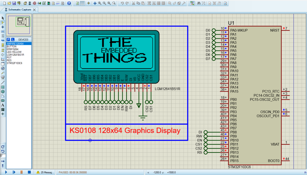
That’s all!
If you have any questions or suggestions don’t hesitate to leave a comment below.