
In this article, explore how to generate a sinus wave with the STM32 AD5621 DAC for precise signal output.
Things used in this project
Software apps and online services:
1- STMicroelectronics STM32CubeMX
2- STMicroelectronics STM32CubeIDE
3- Proteus 8
Generating Sinusoidal Waveforms Using a DAC in Embedded Systems
In embedded systems, generating analog signals from digital data is crucial for applications like audio processing, sensor simulation, and control systems. Digital-to-Analog Converters (DACs) convert digital values from microcontrollers into corresponding analog voltages, with sinusoidal waveforms being a fundamental choice due to their smooth periodic nature. Ensuring accurate, stable, and efficient conversion is a challenge, which is where precision DACs like the AD5621 excel. This 12-bit buffered DAC features low power consumption, rail-to-rail output, and operates within a 2.7V to 5.5V supply range, making it ideal for portable or battery-powered devices.
Understanding the AD5621 DAC
The AD5621 belongs to the nanoDAC® family, providing high precision with minimal power requirements. It operates with a versatile 3-wire serial interface compatible with multiple standards like SPI, making it easy to integrate into most embedded systems. The device can output smooth analog signals, thanks to its on-chip precision output amplifier that enables rail-to-rail operation. This means the DAC can generate output voltages ranging from 0V to the full power supply voltage (VDD).
The AD5621 also features a power-down mode, reducing current consumption to as low as 0.2 µA, which is a significant advantage for battery-operated systems. Its power-on reset function ensures that the DAC powers up to 0V, preventing any unexpected signals until a valid digital input is provided. Additionally, the high speed of its serial interface, capable of clock rates up to 30 MHz, allows for fast updates, making it well-suited for dynamic signal generation such as sinusoidal waveforms.
Why Generate Sinusoidal Waves?
Sinusoidal waves are essential in engineering and science, serving as building blocks in audio processing and as smooth modulation signals in control systems. Accurately generating these waves using a microcontroller and a DAC enables engineers to simulate real-world signals effectively. By inputting calculated digital values that represent points on a sine curve into the DAC, embedded systems can produce precise sinusoidal waveforms. The waveform’s accuracy relies on the DAC’s resolution and the system’s processing and communication speed.
Using the STM32 Microcontroller with the AD5621 DAC
In this project, we will utilize the STM32 microcontroller to drive the AD5621 DAC for generating a sinusoidal waveform. The STM32’s built-in SPI peripheral facilitates communication with the AD5621, allowing it to send digital values that represent the sine wave. The DAC then converts these values into corresponding analog voltages, producing a smooth sine wave output.
The STM32 AD5621 DAC combination offers a robust solution for generating high-quality analog signals. The STM32’s processing power allows for real-time calculation or lookup of sine wave values, while the AD5621’s 12-bit resolution ensures accurate and stable output waveforms.
Key Features of This Implementation:
- High Precision: The 12-bit resolution of the AD5621 ensures smooth transitions between digital-to-analog conversions.
- Low Power Consumption: The AD5621 operates with minimal power, making it ideal for embedded applications, particularly in portable devices.
- Simple Integration: The SPI interface allows for easy communication between the STM32 microcontroller and the DAC, enabling fast updates.
- Real-Time Waveform Generation: The STM32 can compute or retrieve sine wave data points in real-time, ensuring continuous signal generation without interruptions.
STM32CubeMX Configuration:
- Open CubeMX & Create New Project Choose The Target MCU STM32F103C6 & Double-Click Its Name
- Go To The Clock Configuration & Set The System Clock To 16MHz
Configuration for the SPI Mode:
- In the Categories tab, select the SPI1 & Transmit Only Master
- In the Basic Parameters set Data Size to 16 Bits
- In the clock parameters, set the prescaler to 2 to achieve a baud rate of 8.0 Mbits/s.
Configuration for the GPIO Mode:
- Configure The GPIO Pins [PA4] as Output Pins
- Generate The Initialization Code & Open The Project In CubeIDE
STM32CubeIDE Configuration:
- Write The Application Layer Code
- main.c
- /* Includes ------------------------------------------------------------------*/
- #include "main.h"
- /* Private includes ----------------------------------------------------------*/
- /* USER CODE BEGIN Includes */
- #include<AD5621.h>
- /* USER CODE END Includes */
- /* Private variables ---------------------------------------------------------*/
- SPI_HandleTypeDef hspi1;
- /* USER CODE BEGIN PV */
- const uint16_t SINE_POINTS = 360;
- uint16_t sine_table[360];
- /* USER CODE END PV */
- /* Private function prototypes -----------------------------------------------*/
- void SystemClock_Config(void);
- static void MX_GPIO_Init(void);
- static void MX_SPI1_Init(void);
- /**
- * @brief The application entry point.
- * @retval int
- */
- int main(void)
- {
- /* Reset of all peripherals, Initializes the Flash interface and the Systick. */
- HAL_Init();
- /* Configure the system clock */
- SystemClock_Config();
- /* Initialize all configured peripherals */
- MX_GPIO_Init();
- MX_SPI1_Init();
- /* USER CODE BEGIN 2 */
- // Initialize AD5601 with SPI handle, CS pin, and CS GPIO port
- ad5621_Init(&hspi1, GPIO_PIN_4, GPIOA);
- // Generate the sine table
- ad5621_GenerateSineTable(sine_table, SINE_POINTS);
- /* USER CODE END 2 */
- /* Infinite loop */
- /* USER CODE BEGIN WHILE */
- while (1)
- {
- /* USER CODE END WHILE */
- /* USER CODE BEGIN 3 */
- for (int i = 0; i < SINE_POINTS; i++)
- {
- ad5621_SendToDAC(sine_table[i]);
- HAL_Delay(1); // Adjust delay if needed
- }
- }
- /* USER CODE END 3 */
- }
Proteus Configuration :
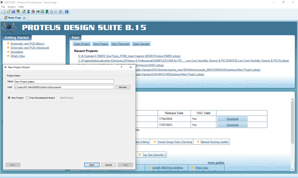
- Open Proteus & Create New Project and click next
- Click on Pick Device
- Search for STM32F103C6 & AD5621
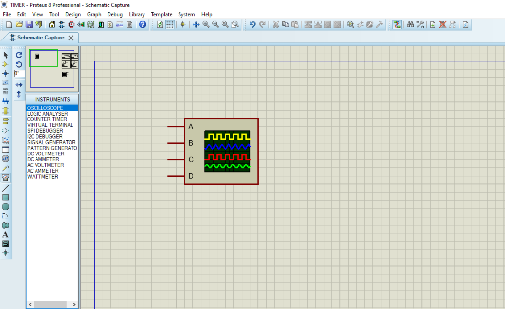
- Click on Virtual Instrumets Mode then choose OSCILLOSCOPE
- Click on Terminal Mode then choose (DYNAMIC&POWER &GROUND)
- finally make the circuit below and start the simulation
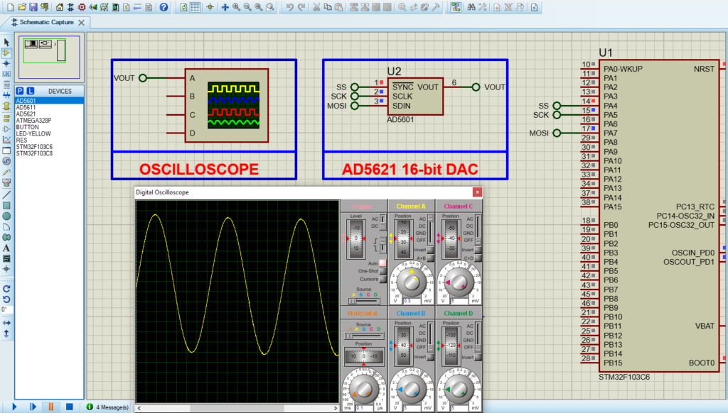
That’s all!
If you have any questions or suggestions don’t hesitate to leave a comment below