
In this article, we explore how to use the STM32 12-bit DAC MCP4921 for generating precise analog signals.
Things used in this project
Software apps and online services:
1- STMicroelectronics STM32CubeMX
2- STMicroelectronics STM32CubeIDE
3- Proteus 8
Generating Analog Signals Using 12-bit DAC MCP4921 and STM32
In this project, we will explore the MCP4921, a 12-bit Digital-to-Analog Converter (DAC) from Microchip Technology, and interface it with an STM32 microcontroller. The MCP4921 is designed for high accuracy and low noise performance, making it ideal for various industrial applications such as sensor calibration, motor control, and signal generation. By using the SPI communication protocol, the STM32 microcontroller can easily control the MCP4921 to generate precise analog signals from digital inputs.
Overview of the MCP4921 DAC:
The MCP4921 is a 12-bit, single-channel DAC that offers excellent accuracy with a typical Differential Nonlinearity (DNL) of ±0.2 LSB and an Integral Nonlinearity (INL) of ±2 LSB. It operates within a voltage range of 2.7V to 5.5V, making it suitable for low-power applications. The DAC also supports rail-to-rail output, ensuring it can fully utilize the entire voltage range.
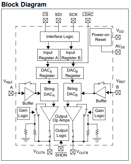
A key feature of the MCP4921 is its use of an SPI interface for communication, supporting clock speeds up to 20 MHz. This enables fast data transfer between the microcontroller and the DAC, ensuring high-speed signal generation. Additionally, the MCP4921 offers a selectable gain of either unity or 2x, allowing for flexible signal amplitude control based on your application needs.
The MCP4921 features a fast settling time of 4.5 µs, making it ideal for applications where rapid signal updates are required. It also includes an external reference voltage (VREF) input for precise control over the output range.
Applications and Specifications of the MCP4921:
The MCP4921 is versatile and can be used in a wide range of applications, including:
- Set Point or Offset Trimming: Adjusting output levels for systems that require calibration.
- Sensor Calibration: Generating analog voltages for calibrating sensors such as pressure or temperature sensors.
- Motor Control: Adjusting the speed or position of motors by generating precise analog control signals.
- Portable Devices: Suitable for battery-powered applications due to its low power consumption.
The MCP4921 operates in temperatures ranging from -40°C to +125°C, making it suitable for industrial environments. The device also provides electrostatic discharge (ESD) protection of over 4 kV on all pins, ensuring robustness in electrically noisy environments.
Pin Descriptions and Circuit Configuration:
- VDD: Supply voltage pin for powering the DAC, operating in a range of 2.7V to 5.5V.
- VREF: External reference voltage input, which determines the full-scale output range of the DAC.
- CS (Chip Select): SPI control pin used to enable communication with the device.
- SCK (Serial Clock): SPI clock pin that synchronizes the data transfer.
- SDI (Serial Data In): SPI data input pin where digital data is sent to the DAC.
- LDAC (Latch DAC): When pulled low, this pin allows the DAC output to update. It can be used to simultaneously update multiple DACs.
- VOUT: The analog output pin where the generated voltage appears.
This project illustrates how to interface an STM32 microcontroller with the MCP4921 12-bit DAC using SPI communication. The code generates analog voltage outputs that switch between 0V and 5V, showcasing the DAC’s capabilities. By initializing the DAC and sending output values through SPI, the project emphasizes real-time control of analog signals. It highlights efficient SPI communication and modular programming, making it ideal for applications requiring precise digital-to-analog conversion, such as generating control signals for motors or simulating sensor outputs.
STM32CubeMX Configuration:
- Open CubeMX & Create New Project Choose The Target MCU STM32F103C6 & Double-Click Its Name
- Go To The Clock Configuration & Set The System Clock To 8MHz
Configuration for the SPI Mode:
- In the Categories tab, select the SPI1 & Transmit Only Master
- In the clock parameters, set the prescaler to 4 to achieve a baud rate of 4.0 Mbits/s.
Configuration for the GPIO Mode:
- Configure The GPIO Pins [PA4] as Output Pins
Configuration for the UART Mode:
- Enable USART1 Module (Asynchronous Mode)
- Set the USART1 communication parameters (baud rate = 115200, parity=NON, stop bits =1, and word length = 8bits)
- Generate The Initialization Code & Open The Project In CubeIDE
STM32CubeIDE Configuration:
- Write The Application Layer Code
- main.c
/* Includes ------------------------------------------------------------------*/
#include "main.h"

/* Private includes ----------------------------------------------------------*/
/* USER CODE BEGIN Includes */
#include "MCP492X.h"        // Include the MCP492X header


/* Private variables ---------------------------------------------------------*/
SPI_HandleTypeDef hspi1;

UART_HandleTypeDef huart1;

/* USER CODE BEGIN PV */
DAC_MCP49x1_HandleTypeDef hdac;

#define CS_ADC_PIN GPIO_PIN_4
#define CS_ADC_PORT GPIOA
#define CS_DAC_PIN GPIO_PIN_9
#define CS_DAC_PORT GPIOA
/* USER CODE END PV */

/* Private function prototypes -----------------------------------------------*/
void SystemClock_Config(void);
static void MX_GPIO_Init(void);
static void MX_SPI1_Init(void);
static void MX_USART1_UART_Init(void);

/**
  * @brief  The application entry point.
  * @retval int
  */
int main(void)
{

  /* Reset of all peripherals, Initializes the Flash interface and the Systick. */
  HAL_Init();

  /* Configure the system clock */
  SystemClock_Config();

  /* Initialize all configured peripherals */
  MX_GPIO_Init();
  MX_SPI1_Init();
  MX_USART1_UART_Init();
  /* USER CODE BEGIN 2 */
  // Initialize the MCP492X
  DAC_MCP49x1_Init(&hdac, MCP4921, &hspi1, GPIOA, GPIO_PIN_4, NULL, 0);
   /* USER CODE END 2 */

  /* Infinite loop */
  /* USER CODE BEGIN WHILE */
  while (1)
  {
    /* USER CODE END WHILE */

    /* USER CODE BEGIN 3 */
    DAC_MCP49x1_Output(&hdac, 0);
    HAL_Delay(100);
    DAC_MCP49x1_Output(&hdac, 4095);
    HAL_Delay(100);
  }
  /* USER CODE END 3 */
}
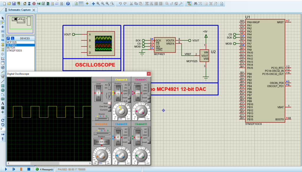
Proteus Configuration :
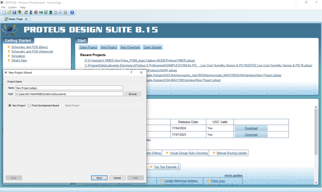
- Open Proteus & Create New Project and click next
- Click on Pick Device
- Search for STM32F103C6 & MCP4921& MCP1525
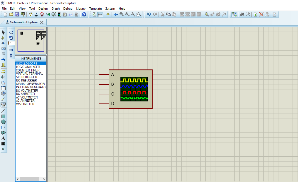
- Click on Virtual Instrumets Mode then choose OSCILLOSCOPE
- Click on Terminal Mode then choose (DYNAMIC&POWER &GROUND)
- finally make the circuit below and start the simulation
That’s all!
If you have any questions or suggestions don’t hesitate to leave a comment below