
In this article, we will discuss Servo Motors Control with STM32, covering the basics of servo motors and techniques for precise movement using PWM signals.
Things used in this project
Software apps and online services:
1- STMicroelectronics STM32CubeMX
2- STMicroelectronics STM32CubeIDE
3- Proteus 8
Controlling Servo Motors with STM32 Microcontrollers
In this project, we will learn how to control servo motors using STM32 microcontrollers by utilizing Pulse Width Modulation (PWM) to achieve precise positioning. Servo motors are crucial components in robotics and automation due to their accurate control over angular movement. They are widely used in various applications, from hobby projects to complex industrial systems. Through this project, you’ll understand how to configure PWM on the STM32 to control a servo motor’s position efficiently.
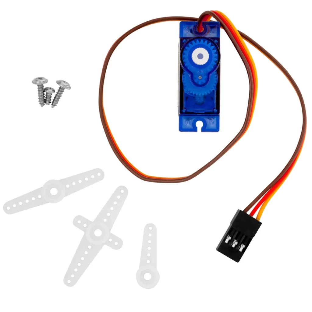
What is a Servo Motor?:
Servo motors are designed for precise control of position, speed, and acceleration. Unlike standard DC motors, which rotate continuously, servo motors respond to (PWM) control signals to move to a specific angle and hold that position. This is achieved through a feedback mechanism that ensures the motor maintains the correct position based on the input signal.
How Servo Motors Work?:
Servo motors function through a closed-loop control system, utilizing feedback to adjust their movement. Here’s how they work:
- Control Signal: The STM32 microcontroller sends a PWM signal to the servo. The duration of the pulse determines the target position of the servo motor shaft.
- Position Sensing: A potentiometer inside the servo continuously monitors the current position of the shaft, generating a voltage proportional to that position.
- Error Correction: The control circuit compares the actual position (from the potentiometer) with the target position (from the input signal). If there’s any discrepancy, the circuit commands the motor to correct its position.
- Feedback Loop: This adjustment process continues until the servo reaches the desired position, ensuring smooth and accurate control.
PWM and Servo Motor Control:
Pulse Width Modulation (PWM) is a method used to create analog signals from digital sources by adjusting the duration of pulses within a set time frame. This technique is particularly useful for controlling servo motors, as the width of each pulse determines how far the servo arm will turn.
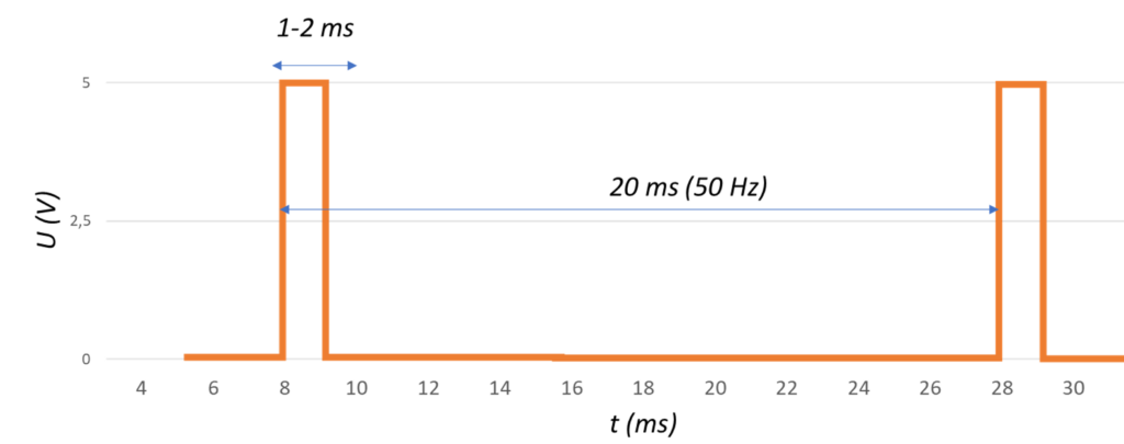
For servo motors, PWM signals consist of a series of pulses within a specific period, typically 20 milliseconds (ms) for standard hobby servos, which equates to a frequency of 50 Hz. The key element of PWM here is the “high” time duration of each pulse, known as the pulse width. This directly affects the position of the servo’s output shaft.
For most hobbyist servo motors:
- A pulse width of 1 ms generally moves the motor to 0° (its minimum position).
- A pulse width of 2 ms moves it to 180° (its maximum position).
By varying the pulse width between these limits, you can achieve smooth and accurate adjustments in the servo’s positioning. This makes PWM an essential technique for applications requiring precise motion control.
To kickstart this project, we will focus on learning how to control a servo motor using PWM signals generated by an STM32 microcontroller. We’ll begin by implementing a button-driven interface that allows users to set the servo’s position at predefined angles (45°, 90°, 135°, and 180°). Additionally, we’ll explore how to utilize HAL library functions to configure both GPIO and Timer settings, ensuring smooth control of the servo’s movements. This hands-on project will provide valuable experience in integrating hardware components and developing code for real-time control applications.
STM32CubeMX Configuration:
- Open CubeMX & Create New Project Choose The Target MCU STM32F103C6 & Double-Click Its Name
- Go To The Clock Configuration & Set The System Clock To 60MHz
Configuration for the TIMER PWM Mode:
- In the Categories tab, select the TIM2 then Enable Internal Clock & PWM Generation Channel 1
- In the Counter settings tab, set the (Prescaler = 16-1 & Counter Peroid = 20000-1)
- In the PWM Generation Channel set ( Mode : PWM mode 1 & Pulse = 0 )
Configuration for the GPIO Mode:
- Configure The GPIO Pins [PB0 .. PB3] as Input Pins
- Generate The Initialization Code & Open The Project In CubeIDE
STM32CubeIDE Configuration :
Initialization and Servo Angle Control
First, this section of the code initializes the necessary header files and defines the GPIO pins for buttons controlling the servo motor’s angles. It declares private variables, including a timer handle and the current angle of the servo, starting at 0 degrees. The SetServoAngle function accepts an angle input, validates it within the range of 0 to 180 degrees, calculates the corresponding PWM pulse width, and updates the timer’s compare value to adjust the servo’s position.
/* Includes ------------------------------------------------------------------*/
#include "main.h"

/* Private define ------------------------------------------------------------*/
// Button definitions
#define BTN_45_PIN  GPIO_PIN_0
#define BTN_90_PIN  GPIO_PIN_1
#define BTN_N45_PIN GPIO_PIN_2
#define BTN_N90_PIN GPIO_PIN_3
#define BTN_PORT    GPIOB

/* Private variables ---------------------------------------------------------*/
TIM_HandleTypeDef htim2;
int16_t currentAngle = 0;  // Start at 90 degrees

/* Private function prototypes -----------------------------------------------*/
void SystemClock_Config(void);
static void MX_GPIO_Init(void);
static void MX_TIM2_Init(void);

/* USER CODE BEGIN 0 */
void SetServoAngle(int16_t angle) {
    /* Ensure angle is within valid range */
    if (angle < 0) angle = 0;
    if (angle > 180) angle = 180;

    /* Calculate pulse width in microseconds */
    uint32_t pulse = (angle * 1000) / 180 + 1000; // Calculate pulse width in microseconds
    __HAL_TIM_SET_COMPARE(&htim2, TIM_CHANNEL_1, pulse); // Set the PWM pulse width for the servo

    currentAngle = angle;  // Update current angle
}
Main Function and Button Checks
In this part, the CheckButtons function reads the state of the GPIO-connected buttons and sets the servo angle based on which button is pressed: 45°, 90°, 135°, or 180°. The main function initializes the STM32 HAL, configures the system clock, and sets up the GPIO and Timer 2 for PWM. Once the setup is complete, it starts PWM generation and enters an infinite loop. This loop continuously checks the button states to update the servo position, with a brief delay to debounce the button presses.
void CheckButtons(void) {
    if (HAL_GPIO_ReadPin(BTN_PORT, BTN_45_PIN) == GPIO_PIN_SET) {
        SetServoAngle(45); // Set servo to 45 degrees
    } else if (HAL_GPIO_ReadPin(BTN_PORT, BTN_90_PIN) == GPIO_PIN_SET) {
        SetServoAngle(90); // Set servo to 90 degrees
    } else if (HAL_GPIO_ReadPin(BTN_PORT, BTN_N45_PIN) == GPIO_PIN_SET) {
        SetServoAngle(135); // Set servo to 135 degrees
    } else if (HAL_GPIO_ReadPin(BTN_PORT, BTN_N90_PIN) == GPIO_PIN_SET) {
        SetServoAngle(180); // Set servo to 180 degrees
    } else {
        SetServoAngle(currentAngle); // Maintain the current angle
    }
}

/**
  * @brief  The application entry point.
  * @retval int
  */
int main(void) {
    HAL_Init(); // Initialize the HAL Library
    SystemClock_Config(); // Configure the system clock
    MX_GPIO_Init(); // Initialize GPIO
    MX_TIM2_Init(); // Initialize Timer 2 for PWM

    HAL_TIM_PWM_Start(&htim2, TIM_CHANNEL_1); // Start PWM on Timer Channel 1

    /* Infinite loop */
    while (1) {
        CheckButtons(); // Continuously check button states
        HAL_Delay(50); // Delay to debounce button presses
    }
}
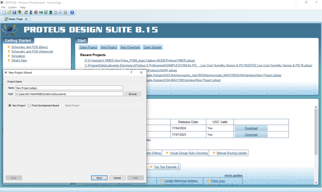
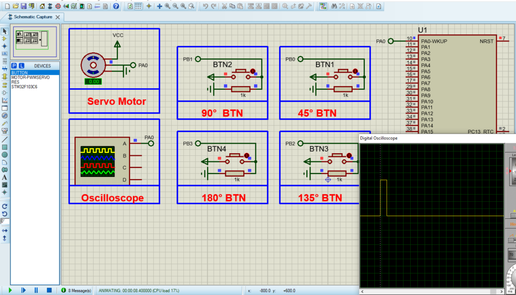
Proteus Configuration :
- Open Proteus & Create New Project and click next
- Click on Pick Device
- Search for STM32F103C6 & LED-RED & RES
- finally make the circuit below and start the simulation
That’s all!
If you have any questions or suggestions don’t hesitate to leave a comment below.
1 comment
[…] In this project, we will explore how to interface the PIC16F877A microcontroller with a servo motor to achieve precise position control, making it ideal for robotics and automation systems. For additional insights, check out a related project: “Controlling Servo Motors with STM32 Microcontrollers.” […]