
In this article, we will explore how to integrate a Real-Time Clock (RTC) with an STM32 microcontroller.
Things used in this project
Software apps and online services:
1- STMicroelectronics STM32CubeMX
2- STMicroelectronics STM32CubeIDE
3- Proteus 8
Real-Time Clock (RTC) and Its Application in STM32
Understanding Real-Time Clocks (RTC):
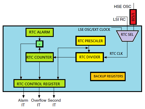
A Real-Time Clock (RTC) is a critical component in embedded systems that maintains accurate time and date tracking even when the power is off. This capability allows RTCs to function independently of the main processor, making them essential for devices that require precise timing without continuous processor intervention. RTCs find applications across various domains, including clocks, watches, washing machines, medicine dispensers, and data loggers. Unlike general-purpose timers in microcontrollers that focus on PWM generation and waveform tasks, RTCs provide enhanced accuracy for timekeeping.
Traditional 8-bit microcontrollers, such as PICs and AVRs, often lack integrated RTC modules. This limitation necessitates the use of external RTC chips like the DS1302 or PCF8563. However, modern microcontrollers like the STM32 come equipped with built-in RTC functionality. This advancement eliminates the need for additional hardware, saving cost, space, and design complexity. As a result, developers can create smarter and more compact devices with ease.
The RTC Alarm Feature:
The RTC Alarm is a specialized feature that triggers an event at a predefined time or date. This functionality is crucial for applications requiring timed operations. You can configure it to wake the system from low-power modes, such as Standby or Sleep mode, or to execute a specific task when the specified time or date arrives. The ability to operate independently from the main processor enhances the efficiency of embedded systems, allowing them to conserve power while remaining responsive.
Why Use RTC Alarms?:
- Low-Power Management: Minimizing power consumption is a significant concern in embedded systems, especially for battery-operated devices. The RTC Alarm can wake the microcontroller from a low-power state at a specific time. This feature makes it ideal for systems that need to remain in a power-saving mode for extended periods, executing tasks only at designated intervals.
- Scheduled Events: RTC Alarms facilitate the scheduling of tasks at predetermined times. For instance, a system can be programmed to send sensor data every hour, or an alarm can trigger notifications at specific times. This enhances the functionality of time-dependent applications.
- Time-Sensitive Applications: Applications that require operations based on real-world time, such as alarms, clocks, or timed data logging, benefit from RTC alarms. These alarms ensure that time-sensitive operations execute reliably and accurately.
- Autonomous Wake-Up: An RTC Alarm can autonomously wake the microcontroller to perform critical tasks, even when the main processor is in a sleep or standby state. This capability reduces the need for manual intervention and simplifies power management in embedded systems.
To kickstart this project, we will implement a Real-Time Clock (RTC) using an STM32 microcontroller. Our primary goal is to display the current time and date on an ST7735 TFT display while allowing users to set these values through UART (Universal Asynchronous Receiver-Transmitter). Specifically, we will configure the RTC module to keep accurate time, establish UART communication for user input, and utilize the ST7735 display for visual output.
STM32CubeMX Configuration:
- Open CubeMX & Create New Project Choose The Target MCU STM32F103C6 & Double-Click Its Name
- Go To The Clock Configuration & Set The System Clock To 72MHz
Configuration for the RTC Mode:
- In the Categories tab, (Activate Clock source calendar)
- In Parameter Settings Enbale auto Predivider Calculation & Asynchronous Predevider value
Configuration for the GPIO Mode:
- Configure The GPIO Pins [PB12 .. PB14] as Input Pins
Configuration for the SPIMode:
- In the Categories tab, select the SPI1 & Transmit Only Master
- In the Parameter settings tab, set the Prescaler (for baud Rate) to 4
Configuration for the UART Mode:
- Enable USART1 Module (Asynchronous Mode)
- Set the USART1 communication parameters (baud rate = 115200, parity=NON, stop bits =1, and word length = 8bits)
- Generate The Initialization Code & Open The Project In CubeIDE
STM32CubeIDE Configuration:
Includes and Initialization
This section includes the core logic for validating the date and time formats received via UART. We ensure the inputs are correct before setting them on the RTC. Functions like validateDate, validateTime, and checkInputFormat check the input validity. The Set_RTC_TimeAndDate function solicits, parses, and validates user inputs. If the inputs are valid, the RTC updates with the new time and date values. This section emphasizes user interaction and error handling for setting up the RTC.
- /* Includes ------------------------------------------------------------------*/
- #include "main.h"
- /* Private includes ----------------------------------------------------------*/
- /* USER CODE BEGIN Includes */
- #include "fonts.h"
- #include "ST7735.h"
- #include <stdio.h>
- #include <string.h>
- /* USER CODE END Includes */
- /* Private variables ---------------------------------------------------------*/
- RTC_HandleTypeDef hrtc;
- SPI_HandleTypeDef hspi1;
- UART_HandleTypeDef huart1;
- /* USER CODE BEGIN PV */
- char time[30];
- char date[30];
- char uart_buf[30];
- RTC_TimeTypeDef sTime;
- RTC_DateTypeDef sDate;
- /* USER CODE END PV */
- /* Private function prototypes -----------------------------------------------*/
- void SystemClock_Config(void);
- static void MX_GPIO_Init(void);
- static void MX_SPI1_Init(void);
- static void MX_RTC_Init(void);
- static void MX_USART1_UART_Init(void);
- /* USER CODE BEGIN PFP */
- /* USER CODE END PFP */
- /* Private user code ---------------------------------------------------------*/
- /* USER CODE BEGIN 0 */
- // State variable to check if the configuration is done
- uint8_t configComplete = 0; // Configuration status
RTC Configuration and Input Handling
This part includes the core logic for validating the date and time formats received via UART, as well as ensuring the inputs are correct before setting them on the RTC. Functions like validateDate, validateTime, and checkInputFormat check the input validity. The Set_RTC_TimeAndDate function is where user inputs are solicited, parsed, and validated. If inputs are valid, the RTC is updated with the new time and date values. This section emphasizes user interaction and error handling for setting up the RTC.
- // Function to validate the date
- bool validateDate(RTC_DateTypeDef *date) {
- // Array with the number of days in each month
- uint8_t daysInMonth[] = {31, 28, 31, 30, 31, 30, 31, 31, 30, 31, 30, 31};
- // Validate month
- if (date->Month < 1 || date->Month > 12) {
- return false;
- }
- // Validate day
- if (date->Date < 1 || date->Date > daysInMonth[date->Month - 1]) {
- return false;
- }
- // The date is valid
- return true;
- }
- // Function to validate the time
- bool validateTime(RTC_TimeTypeDef *time) {
- // Validate hours, minutes, and seconds
- if (time->Hours > 23 || time->Minutes > 59 || time->Seconds > 59) {
- return false;
- }
- // The time is valid
- return true;
- }
- // Function to check format of the input strings
- bool checkInputFormat(const char *input, const char *format) {
- // Check for the correct length
- if (strlen(input) != strlen(format)) {
- return false;
- }
- for (size_t i = 0; i < strlen(format); i++) {
- if (format[i] == ':') {
- if (input[i] != ':') return false; // Expecting ':' in time
- } else if (format[i] == '/') {
- if (input[i] != '/') return false; // Expecting '/' in date
- } else if (!isdigit(input[i])) {
- return false; // Expecting a digit
- }
- }
- return true; // Format is correct
- }
- void Set_RTC_TimeAndDate(void) {
- RTC_TimeTypeDef sTime;
- RTC_DateTypeDef sDate;
- char uart_buf[50]; // Ensure this is appropriately sized for your messages
- while (1) { // Loop until valid date and time are set
- // Get the time from UART
- const char *timePrompt = "Enter Time (HH:MM:SS): ";
- HAL_UART_Transmit(&huart1, (uint8_t *)timePrompt, strlen(timePrompt), HAL_MAX_DELAY);
- UART_ReceiveString(uart_buf, sizeof(uart_buf)); // Assuming uart_buf is defined
- // Validate the format of the input
- if (!checkInputFormat(uart_buf, "HH:MM:SS")) {
- const char *errorMsg = "Invalid time format. Please use HH:MM:SS\n\r";
- HAL_UART_Transmit(&huart1, (uint8_t *)errorMsg, strlen(errorMsg), HAL_MAX_DELAY);
- continue; // Prompt for input again
- }
- // Parse the received time from uart_buf
- sTime.Hours = (uart_buf[0] - '0') * 10 + (uart_buf[1] - '0');
- sTime.Minutes = (uart_buf[3] - '0') * 10 + (uart_buf[4] - '0');
- sTime.Seconds = (uart_buf[6] - '0') * 10 + (uart_buf[7] - '0');
- // Prompt for date input
- const char *datePrompt = "Enter Date (DD/MM/YY): ";
- HAL_UART_Transmit(&huart1, (uint8_t *)datePrompt, strlen(datePrompt), HAL_MAX_DELAY);
- UART_ReceiveString(uart_buf, sizeof(uart_buf)); // Assuming uart_buf is defined
- // Validate the format of the input
- if (!checkInputFormat(uart_buf, "DD/MM/YY")) {
- const char *errorMsg = "Invalid date format. Please use DD/MM/YY\n\r";
- HAL_UART_Transmit(&huart1, (uint8_t *)errorMsg, strlen(errorMsg), HAL_MAX_DELAY);
- continue; // Prompt for input again
- }
- // Parse the received date from uart_buf
- sDate.Date = (uart_buf[0] - '0') * 10 + (uart_buf[1] - '0');
- sDate.Month = (uart_buf[3] - '0') * 10 + (uart_buf[4] - '0');
- sDate.Year = (uart_buf[6] - '0') * 10 + (uart_buf[7] - '0'); // Two-digit year
- // Validate date and time
- bool dateValid = validateDate(&sDate);
- bool timeValid = validateTime(&sTime);
- if (!dateValid || !timeValid) {
- const char *errorMsg = "Error in time or in date. Please try again.\n\r";
- HAL_UART_Transmit(&huart1, (uint8_t *)errorMsg, strlen(errorMsg), HAL_MAX_DELAY);
- continue; // Prompt for input again
- }
- // If valid, set the time and date
- HAL_RTC_SetTime(&hrtc, &sTime, RTC_FORMAT_BIN);
- HAL_RTC_SetDate(&hrtc, &sDate, RTC_FORMAT_BIN);
- const char *successMsg = "RTC set successfully\n\r";
- HAL_UART_Transmit(&huart1, (uint8_t *)successMsg, strlen(successMsg), HAL_MAX_DELAY);
- break; // Exit the loop since time and date are set successfully
- }
- }
- void UART_ReceiveString(char *buffer, uint16_t bufferSize) {
- uint16_t i = 0;
- char received;
- // Receive each character until '\r' is received or buffer is full
- while (i < bufferSize - 1) {
- HAL_UART_Receive(&huart1, (uint8_t *)&received, 1, HAL_MAX_DELAY);
- if (received == '\r') { // End of input
- break;
- }
- buffer[i++] = received;
- }
- buffer[i] = '\0'; // Null-terminate the string
- }
Main Loop and Display Update
In this final section, the main function initializes the STM32 system, including GPIO, SPI, RTC, and UART peripherals, as well as the ST7735 TFT display. We set the display’s orientation, fill the screen with a background color, and draw borders. In the infinite loop, we fetch the current time and date from the RTC, format it into strings, and display it on the TFT screen. We also send the same information via UART for debugging or logging. The display updates every second, providing a continuous real-time clock interface.
- int main(void)
- {
- /* MCU Configuration--------------------------------------------------------*/
- /* Reset of all peripherals, Initializes the Flash interface and the Systick. */
- HAL_Init();
- /* Configure the system clock */
- SystemClock_Config();
- /* Initialize all configured peripherals */
- MX_GPIO_Init();
- MX_SPI1_Init();
- MX_RTC_Init();
- MX_USART1_UART_Init();
- /* USER CODE BEGIN 2 */
- ST7735_Init(); // Initialize the TFT display
- ST7735_Backlight_On(); // Turn on the display backlight
- // Set the display orientation
- uint8_t rotation = 1; // 1 for portrait or 0 for landscape, based on preference
- ST7735_SetRotation(rotation);
- // Fill the screen with a background color
- ST7735_FillRoundRect(1, 1, 160, 128, 2, ST7735_BLUE); // Blue background
- // Draw screen borders
- for (int x = 0; x < ST7735_GetWidth(); x++) {
- ST7735_DrawPixel(x, 0, ST7735_WHITE); // Top border
- ST7735_DrawPixel(x, ST7735_GetHeight() - 1, ST7735_WHITE); // Bottom border
- }
- for (int y = 0; y < ST7735_GetHeight(); y++) {
- ST7735_DrawPixel(0, y, ST7735_WHITE); // Left border
- ST7735_DrawPixel(ST7735_GetWidth() - 1, y, ST7735_WHITE); // Right border
- }
- /* USER CODE END 2 */
- /* Infinite loop */
- while (1)
- {
- // Get the current time and date from the RTC
- HAL_RTC_GetTime(&hrtc, &sTime, RTC_FORMAT_BIN);
- HAL_RTC_GetDate(&hrtc, &sDate, RTC_FORMAT_BIN);
- // Format the time and date into strings for display
- snprintf(time, sizeof(time), "Time: %02d:%02d:%02d", sTime.Hours, sTime.Minutes, sTime.Seconds);
- snprintf(date, sizeof(date), "Date: %02d/%02d/20%02d", sDate.Date, sDate.Month, sDate.Year);
- // Clear previous text (black background) and display the updated time and date
- ST7735_WriteString(5, 5, time, Font_7x10, ST7735_WHITE, ST7735_BLACK); // Display time
- ST7735_WriteString(5, 20, date, Font_7x10, ST7735_WHITE, ST7735_BLACK); // Display date
- // Send the time and date over UART for logging/debugging
- snprintf(uart_buf, sizeof(uart_buf), "%02d:%02d:%02d - %02d/%02d/20%02d\n\r",
- sTime.Hours, sTime.Minutes, sTime.Seconds, sDate.Date, sDate.Month, sDate.Year);
- HAL_UART_Transmit(&huart1, (uint8_t*)uart_buf, strlen(uart_buf), HAL_MAX_DELAY);
- // Delay for 1 second before updating again
- HAL_Delay(1000);
- }
- }
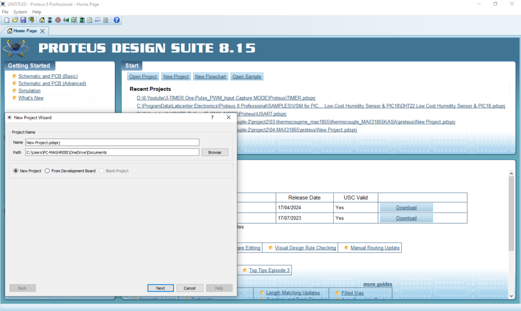
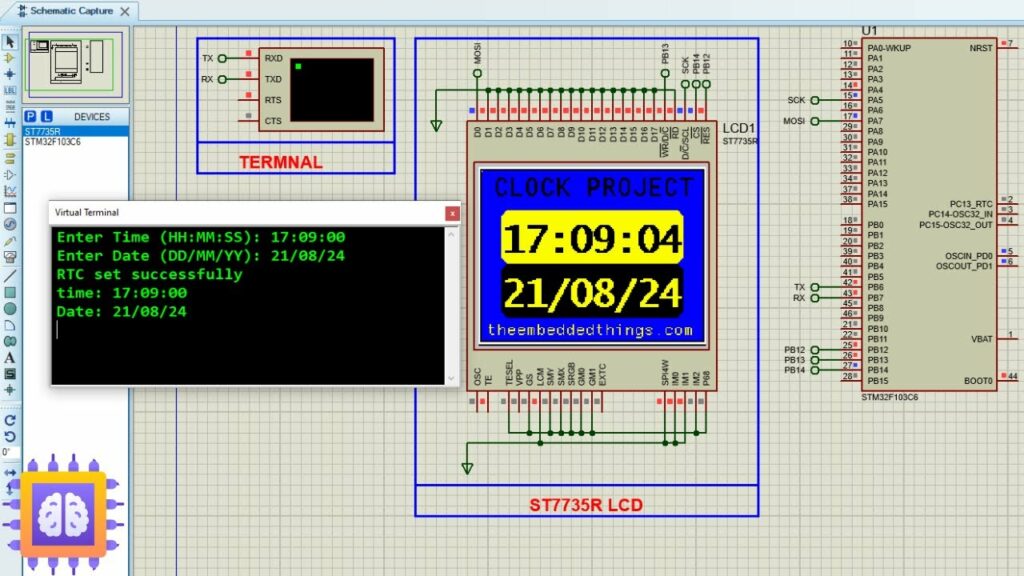
Proteus Configuration :
- Open Proteus & Create New Project and click next
- Click on Pick Device
- Search for STM32F103C8 & ST7735R
- Click on Virtual Instruments Mode then choose Terminal
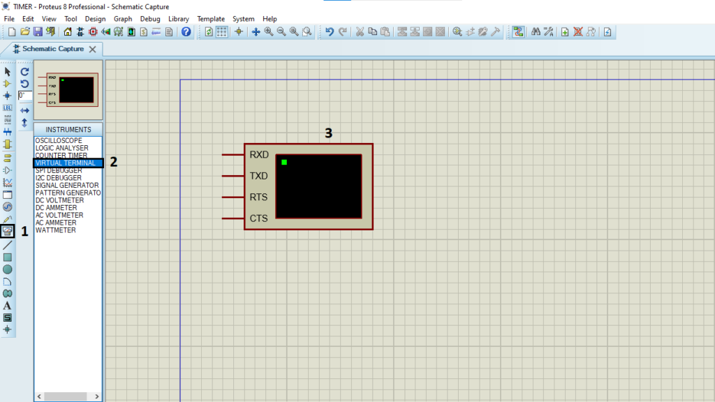
- Click on Terminal Mode then choose (DYNAMIC & POWER &GROUND)
- finally make the circuit below and start the simulation
That’s all!
If you have any questions or suggestions don’t hesitate to leave a comment below.
2 comments
thank you for the tuto , but i can’t find the libraries ?
You’re welcome! You can find the required libraries in the project titled
“STM32 ST7735 TFT Display SPI: A Complete Guide to Interfacing.”
https://theembeddedthings.com/stmp32/interfacing-stm32-with-st7735-display-using-spi/
Feel free to check it out, and let me know if you have any other questions!