
In this article, we will explore MCP3208 STM32 ADC integration, demonstrating how to configure multi-channel setups for efficient analog-to-digital conversion using SPI communication.

Things used in this project
Software apps and online services:
1- STMicroelectronics STM32CubeMX
2- STMicroelectronics STM32CubeIDE
3- Proteus 8
MCP3208 12-Bit Analog-to-Digital Converter Overview
In this project, we explore the MCP3208 from Microchip Technology Inc., a successive approximation 12-bit Analog-to-Digital Converter (ADC) equipped with on-board sample-and-hold circuitry. This device provides high performance and flexibility, which makes it ideal for a wide range of applications. When integrated with STM32 microcontrollers, the MCP3208 communicates seamlessly via SPI . This integration enables efficient multi-channel data acquisition and processing in embedded systems.
Overview of the MCP3208 ADC:
Overview of the MCP3208 ADC: The MCP3208 is a flexible 12-bit Analog-to-Digital Converter (ADC) that can be configured for either four pseudo-differential input pairs or eight single-ended inputs. This configuration allows users to select the most suitable setup for their applications. It provides high precision, featuring a maximum Differential Nonlinearity (DNL) of ±1 Least Significant Bit (LSB). Additionally, the Integral Nonlinearity (INL) is ±1 LSB for the MCP3208-B or ±2 LSB for the MCP3208-C.
This device uses a straightforward SPI (Serial Peripheral Interface) protocol, which allows conversion rates of up to 100,000 samples per second (ksps). Operating within a voltage range of 2.7V to 5.5V, the MCP3208 suits different power supply configurations. It also consumes minimal power, using only 500 nA in standby mode and 320 µA during active operation.
Applications and Ratings of the MCP3208 ADC:
The MCP3208 ADC is highly versatile, making it suitable for various applications such as sensor interfaces, process control, data acquisition, and battery-operated systems. Its flexibility makes it an ideal option for projects that demand precise analog-to-digital conversion.
In terms of specifications, the MCP3208 has a maximum VDD rating of 7.0V and an input/output voltage range from -0.6V to VDD + 0.6V (relative to VSS). It operates reliably in storage temperatures ranging from -65°C to +150°C and functions well at ambient temperatures between -65°C and +125°C. Furthermore, the device tolerates soldering temperatures up to +300°C for a maximum of 10 seconds and offers ESD protection exceeding 4 kV on all pins.
Pin Descriptions:
- Digital Ground (DGND): Provides ground for internal digital circuitry.
- Analog Ground (AGND): Connects to the internal analog circuitry ground.
- Analog Inputs (CH0–CH7): The MCP3208 has eight multiplexed analog inputs. Each pair of channels can be configured as two independent channels in single-ended mode or as a single pseudo-differential input. Channel configuration details are available in the device’s programming sections.
- Serial Clock (CLK): The SPI clock pin starts a conversion and clocks out each bit of the conversion. Minimum clock speed constraints are detailed in the device specifications.
- Serial Data Input (DIN): This pin inputs SPI serial data for loading channel configuration data into the MCP3208.
- Serial Data Output (DOUT): This SPI serial data output pin shifts out the ADC conversion results. Data is output on the falling edge of the clock during conversion.
Chip Select/Shutdown (CS/SHDN): The CS/SHDN pin starts communication with the device when pulled low and transitions it into standby mode when pulled high. This pin must remain high between conversions.
This project demonstrates how to interface an STM32 microcontroller with the MCP3208 12-bit ADC via SPI. It converts analog signals into voltage readings displayed through UART. The code handles both single-ended and differential ADC readings, converts them to voltage using reference voltages, and displays the results in a structured format on a serial terminal. This project emphasizes efficient SPI communication, modular functions, and clear UART output for real-time monitoring, making it ideal for embedded applications that require precise analog data processing.
STM32CubeMX Configuration:
Open CubeMX & Create New Project Choose The Target MCU STM32F103C6 & Double-Click Its Name
- Go To The Clock Configuration & Set The System Clock To 8MHz
- Configure The GPIO Pin PA4 (CS) as Output Pin
- In the Categories tab, select the SPI1 & Full-Duplex Master
- Generate The Initialization Code & Open The Project In CubeIDE
STM32CubeIDE Configuration :
- Write The Application Layer Code
/* USER CODE END Header */
/* Includes ------------------------------------------------------------------*/
#include "main.h"

/* Private includes ----------------------------------------------------------*/
/* USER CODE BEGIN Includes */
#include "mcp3208.h"
#include <stdio.h>
#include <string.h>
/* USER CODE END Includes */

/* Private typedef -----------------------------------------------------------*/
/* USER CODE BEGIN PTD */
MCP3208_HandleTypeDef hmcp3208;
/* USER CODE END PTD */

/* Private variables ---------------------------------------------------------*/
SPI_HandleTypeDef hspi1;
UART_HandleTypeDef huart1;

/* USER CODE BEGIN PV */
#define VREF 2.5 // Reference voltage
#define ADC_RESOLUTION 4096  // 12-bit ADC

const float V_REF = 2.5f;    // Adjust based on your reference voltage
const float V_REF2 = 5.0f;    // Adjust based on your reference voltage

const int ADC_MAX_VALUE = 4095; // MCP3208 is a 12-bit ADC
const int ADC_MAX_VALUE2 = 1024; // MCP3208 is a 12-bit ADC

/* USER CODE END PV */

/* Private function prototypes -----------------------------------------------*/
void SystemClock_Config(void);
static void MX_GPIO_Init(void);
static void MX_SPI1_Init(void);
static void MX_USART1_UART_Init(void);
/* USER CODE BEGIN PFP */

/* USER CODE END PFP */

/* Private user code ---------------------------------------------------------*/
/* USER CODE BEGIN 0 */
void print_uart(const char* str)
{
    HAL_UART_Transmit(&huart1, (uint8_t*)str, strlen(str), HAL_MAX_DELAY);
}

float adc_to_voltage(uint16_t adc_value)
{
    return (float)adc_value * VREF / ADC_RESOLUTION ;

}

int main(void)
{
  /* Reset of all peripherals, Initializes the Flash interface and the Systick. */
  HAL_Init();
  /* Configure the system clock */
  SystemClock_Config();
  /* Initialize all configured peripherals */
  MX_GPIO_Init();
  MX_SPI1_Init();
  MX_USART1_UART_Init();
  /* USER CODE BEGIN 2 */
    // Initialize MCP3208
     hmcp3208.hspi = &hspi1;
     hmcp3208.CS_GPIO_Port = GPIOA;
     hmcp3208.CS_Pin = GPIO_PIN_4;
     MCP3208_Init(&hmcp3208);

     char temp[10];
     int ctr = 0;
  /* USER CODE END 2 */

 /* USER CODE BEGIN WHILE */
  while (1)
  {
    /* USER CODE END WHILE */

    /* USER CODE BEGIN 3 */
      if (ctr == 0)
      {
          HAL_UART_Transmit(&huart1, (uint8_t*)"\n\r", 2, HAL_MAX_DELAY);
          HAL_UART_Transmit(&huart1, (uint8_t*)"\n\r              Single Ended (V)           |    Differential (V)\n\r", 68, HAL_MAX_DELAY);
          HAL_UART_Transmit(&huart1, (uint8_t*)"   0    1    2    3    4    5    6    7  |   0     1    2    3\n\r", 66, HAL_MAX_DELAY);
          HAL_UART_Transmit(&huart1, (uint8_t*)"------------------------------------------------------------------------\n\r", 66, HAL_MAX_DELAY);
          HAL_UART_Transmit(&huart1, (uint8_t*)"\n\r", 2, HAL_MAX_DELAY);
      }

      ctr++;
      if (ctr == 10)
      {
          ctr = 0;
      }

      // Read single-ended values
      for (int i = 0; i < 8; i++)
      {
          uint16_t value = MCP3208_AnalogRead(&hmcp3208, i);
          float voltage = (value * V_REF) / ADC_MAX_VALUE; // Convert to voltage
          sprintf(temp, "%5.2f", voltage);  // Format to 2 decimal places with 5 characters (including leading spaces)
          HAL_UART_Transmit(&huart1, (uint8_t*)temp, strlen(temp), HAL_MAX_DELAY);
      }
      HAL_UART_Transmit(&huart1, (uint8_t*)" | ", 2, HAL_MAX_DELAY);

      // Read differential values
      for (int i = 0; i < 4; i++)
      {
          int16_t diff_value = MCP3208_AnalogReadDif(&hmcp3208, i);
          float diff_voltage = (diff_value * V_REF) / ADC_MAX_VALUE; // Convert to voltage
          sprintf(temp, "%5.2f ", diff_voltage); // Format to 2 decimal places with a single space after the value
          HAL_UART_Transmit(&huart1, (uint8_t*)temp, strlen(temp), HAL_MAX_DELAY);
      }
      HAL_UART_Transmit(&huart1, (uint8_t*)"\r\n", 2, HAL_MAX_DELAY);
      HAL_Delay(1000); // Delay for stability
  }
  /* USER CODE END 3 */
}
Proteus Configuration :
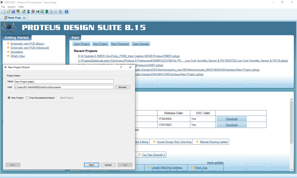
- Open Proteus & Create New Project and click next
- Click on Pick Device
- Search for STM32F103C6 & MCP3008 & POT & RES
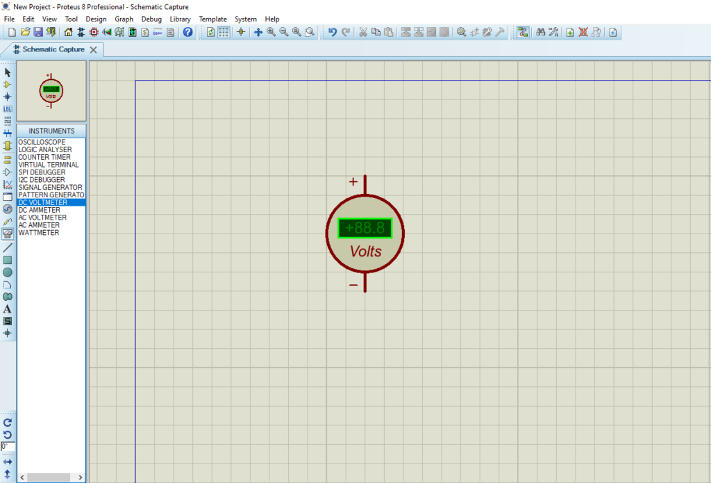
- Click on Virtual Instrumets Mode then choose DCVOLTMETER
- Click on Terminal Mode then choose (DYNAMIC&POWER &GROUND)
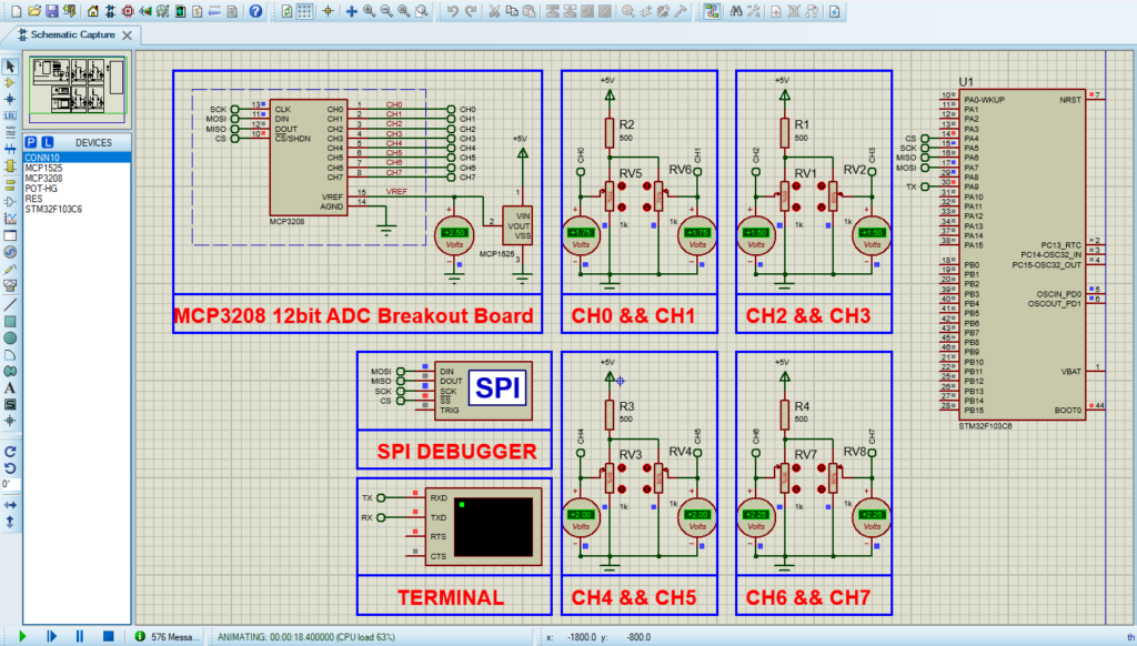
- finally make the circuit below and start the simulation
That’s all!
If you have any questions or suggestions don’t hesitate to leave a comment below