STM32 Thermistors ADC: Mastering Temperature Sensing with Microcontrollers

by Marwen Maghrebi

In this article, we explore using NTC thermistors with STM32 microcontrollers, emphasizing ADC configurations for accurate temperature sensing.

Things used in this project

Software apps and online services

1- STMicroelectronics STM32CubeMX

2- STMicroelectronics STM32CubeIDE

3- Proteus 8

Understanding NTC and PTC Thermistors for STM32 Microcontroller Projects

In this project, we explore thermistors: temperature-sensitive resistors pivotal in electronics for their ability to vary resistance with temperature. Unlike RTDs, which feature a consistent positive temperature coefficient, thermistors can exhibit either positive (PTC) or negative (NTC) coefficients, making them versatile in diverse applications. 

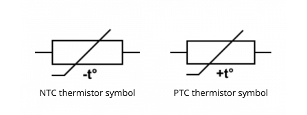
This article delves into the essential characteristics of NTC and PTC thermistors, offering insights into their operational principles and practical applications in electronic projects.


What Are Thermistors Composed Of?:

Thermistors are made from composite materials, usually ceramic, polymer, or semiconductor (typically metal oxides). These materials are formed into various shapes such as discs, beads, or chips. The precise ratio of these composite materials determines the resistance-temperature characteristics of the thermistor, which manufacturers control with great accuracy.

Types of Thermistors:

Thermistors are available in two types: NTC (Negative Temperature Coefficient) and PTC (Positive Temperature Coefficient).

  • NTC Thermistors: An NTC thermistor decreases its resistance as the temperature increases. NTC thermistors are more commonly used in precision temperature measurement applications due to their high sensitivity and faster response rate. They are typically used in applications that require low cost, small size, and restricted temperature range, such as monitoring electronic equipment, household and building controls, scientific laboratories, or cold-junction compensation for thermocouples.
  • PTC Thermistors: A PTC thermistor increases its resistance as the temperature increases. PTC thermistors are primarily used in overcurrent protection circuits or as resettable fuses for safety applications. They exhibit a very small NTC region until reaching their switching point (or Curie point), above which the resistance increases dramatically, thereby reducing the current and preventing damage to the system. The switching point for a PTC thermistor is typically between 60°C and 120°C, making them unsuitable for wide-range temperature monitoring.

Comparison with RTDs:

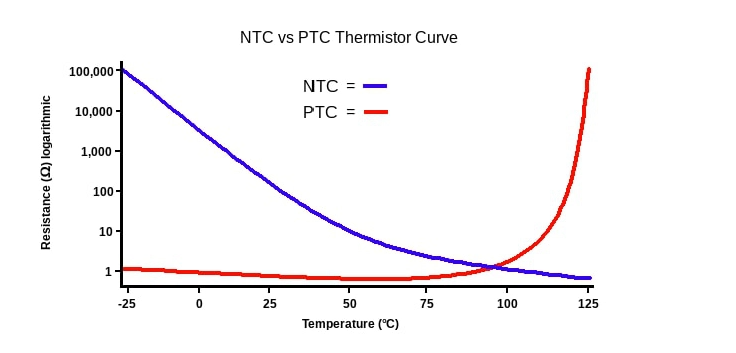
In terms of temperature range, RTDs cover a much wider range (commonly –200°C to +850°C) than thermistors, which have nonlinear (exponential) characteristics. While RTDs are usually available in standardized curves, thermistor curves vary depending on the manufacturer. Thermistors detect changes in temperature much faster than RTDs, delivering quicker feedback. If you want to know more about RTDs, you can find projects in this [link].

Key Characteristics of NTC and PTC Thermistors:

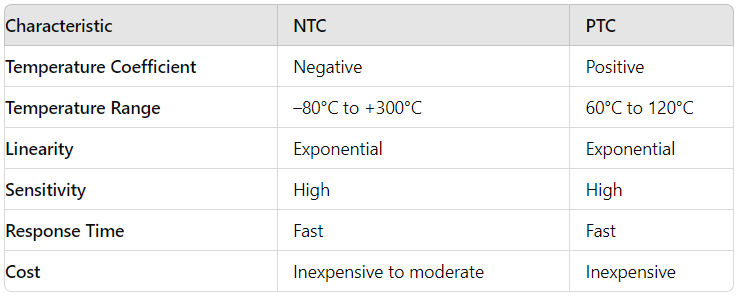
Application Considerations:

  • NTC Thermistors: NTC thermistors are preferred for precision temperature measurement applications due to their high sensitivity and fast response time. They are available with nominal resistances at 25°C, ranging from a few ohms to 10 MΩ. The high resistance values make their front-end circuitry simpler compared to RTDs, as they do not need special wiring configurations to compensate for lead resistance.
  • PTC Thermistors: PTC thermistors are mainly used for overcurrent protection due to their significant resistance increase above the switching point. This characteristic makes them effective in reducing current input to prevent system damage. However, their limited temperature range (60°C to 120°C) restricts their use in broad temperature measurement applications.

This project focuses on using an STM32 microcontroller to measure temperature using an NTC thermistor and the ADC peripheral. Key steps include configuring the ADC for single-channel sampling, setting parameters like SERIESRESISTOR, THERMISTORNOMINAL, and BCOEFFICIENT for accurate temperature conversion using the Steinhart-Hart equation. UART communication is established to transmit real-time temperature data efficiently. Overall, the project aims to achieve precise temperature monitoring and data transmission using STM32’s ADC and UART capabilities.

STM32CubeMX Configuration:

  • Open CubeMX & Create New Project Choose The Target MCU STM32F103C6 & Double-Click Its Name
  • Go To The Clock Configuration & Set The System Clock To 8MHz

Configuration for the ADC Modes:

  • In the Categories tab, select the ADC1 & enable IN4

Configuration for the UART Mode:

  • Enable USART1 Module (Asynchronous Mode)
  • Set the USART1 communication parameters (baud rate = 115200, parity=NON, stop bits =1, and word length = 8bits)
  • Generate The Initialization Code & Open The Project In CubeIDE

STM32CubeIDE Configuration:

  • Write The Application Layer Code
  • main.c
/* Includes ------------------------------------------------------------------*/
#include "main.h"

/* Private includes ----------------------------------------------------------*/
/* USER CODE BEGIN Includes */
#include <stdio.h>
#include <math.h>
#include <string.h>

/* Private define ------------------------------------------------------------*/
/* USER CODE BEGIN PD */
#define NUMSAMPLES 5                  //Number of ADC samples to average for better measurement accuracy
#define SERIESRESISTOR 10000          //Value of the series resistor in ohms
#define THERMISTORNOMINAL 10000       //Nominal resistance of the thermistor at 25°C in ohms
#define TEMPERATURENOMINAL 25           //Nominal temperature for the thermistor resistance in degrees Celsius
#define BCOEFFICIENT 3950              //Beta coefficient of the thermistor, typically between 3000 and 4000
/* USER CODE END PD */

/* Private variables ---------------------------------------------------------*/
ADC_HandleTypeDef hadc1;
UART_HandleTypeDef huart1;

/* USER CODE BEGIN PV */
char buffer[50];                  //Buffer for UART transmission
float samples[NUMSAMPLES];          //Array to store ADC sample values
float average = 0;               //Variable to store the average of ADC samples
float steinhart;                   //Variable to store the calculated temperature in Celsius
uint8_t i;                       //Loop counter for sampling
/* USER CODE END PV */

/* Private function prototypes -----------------------------------------------*/
void SystemClock_Config(void);
static void MX_GPIO_Init(void);
static void MX_ADC1_Init(void);
static void MX_USART1_UART_Init(void);
/* USER CODE BEGIN PFP */

int main(void)
{
  /* Reset of all peripherals, Initializes the Flash interface and the Systick. */
  HAL_Init();
  /* Configure the system clock */
  SystemClock_Config();
  /* Initialize all configured peripherals */
  MX_GPIO_Init();
  MX_ADC1_Init();
  MX_USART1_UART_Init();

  /* USER CODE BEGIN WHILE */
  while (1)
  {
    /* USER CODE END WHILE */
    /* USER CODE BEGIN 3 */
      average = 0;  //Clear previous average value to ensure correct calculation for the new set of samples

      //Collect multiple ADC samples and store them in the array
      for (i = 0; i < NUMSAMPLES; i++) {
          HAL_ADC_Start(&hadc1);                              //Start the ADC conversion
          HAL_ADC_PollForConversion(&hadc1, HAL_MAX_DELAY);   //Wait for the conversion to complete
          samples[i] = HAL_ADC_GetValue(&hadc1);              //Read the ADC conversion result
          HAL_Delay(10);                                      //Delay between samples to stabilize the ADC readings
      }
    
      //Compute the average of the collected ADC samples
      for (i = 0; i < NUMSAMPLES; i++) {
          average += samples[i];  //Sum up all the ADC sample values
      }
      average /= NUMSAMPLES;  //Calculate the average of the ADC samples
      sprintf(buffer, "Average analog reading %.2f \r\n", average);  // Format the average reading for UART output
      HAL_UART_Transmit(&huart1, (uint8_t*)buffer, strlen(buffer), HAL_MAX_DELAY);  //Transmit the average reading via UART
    
      //Convert the average ADC reading to thermistor resistance and calculate temperature
      if (average > 0) {  // Ensure the average is not zero to avoid division errors
          average = 4094 / average - 1;  // Convert ADC reading to resistance using 12-bit ADC resolution
          average = SERIESRESISTOR / average;  // Calculate the thermistor resistance
    
          sprintf(buffer, "Thermistor resistance %.2f \r\n", average);  // Format the resistance value for UART output
          HAL_UART_Transmit(&huart1, (uint8_t*)buffer, strlen(buffer), HAL_MAX_DELAY);  // Transmit the resistance value via UART
    
          // Apply the Steinhart-Hart equation to convert resistance to temperature
          steinhart = average / THERMISTORNOMINAL;  //Compute the ratio of thermistor resistance to nominal resistance
          steinhart = log(steinhart);  //Compute the natural logarithm of the resistance ratio
          steinhart /= BCOEFFICIENT;  //Divide by the thermistor's Beta coefficient
          steinhart += 1.0 / (TEMPERATURENOMINAL + 273.15);  //Add the reciprocal of the nominal temperature in Kelvin
          steinhart = 1.0 / steinhart;  //Compute the reciprocal to get the temperature in Kelvin
          steinhart -= 273.15;  //Convert the temperature from Kelvin to Celsius
    
          sprintf(buffer, "Temperature: %.2f *C\r\n", steinhart);  // Format the temperature value for UART output
          HAL_UART_Transmit(&huart1, (uint8_t*)buffer, strlen(buffer), HAL_MAX_DELAY);  // Transmit the temperature value via UART
      } else {
          sprintf(buffer, "Error: Invalid ADC reading\r\n");  // Handle invalid ADC reading (e.g., division by zero)
          HAL_UART_Transmit(&huart1, (uint8_t*)buffer, strlen(buffer), HAL_MAX_DELAY);  // Transmit the error message via UART
      }
    
      HAL_Delay(1000);  // Wait for 1 second before repeating the loop

  }
  /* USER CODE END 3 */
}

Proteus Configuration :

  • Open Proteus & Create New Project and click next

  • Click on Pick Device
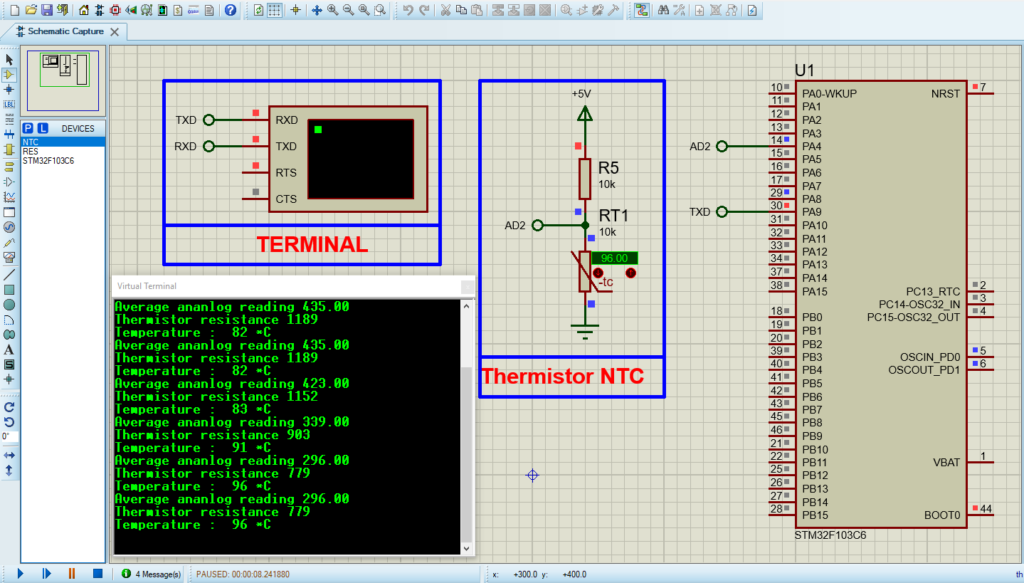
  • Search for STM32F103C6 & NTC & RES
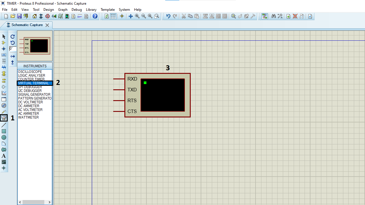
  • Click on Virtual Instruments Mode then choose Terminal

  • Click on Terminal Mode then choose (DEFAULT & POWER &GROUND)
  • finally make the circuit below and start the simulation
Circuit design simulation for STM32 microcontrollers using thermistors for temperature sensing.

That’s all!
If you have any questions or suggestions don’t hesitate to leave a comment below

You Might Also Like

1 comment

DHT11 Sensor with STM32: A Complete Integration Guide - The Embedded Things September 24, 2024 - 11:21 pm

[…] NTC Thermistor: Measures temperature by decreasing resistance as temperature increases, following a negative temperature coefficient (NTC) characteristic. […]

Reply

Leave a Comment


Are you sure want to unlock this post?
Unlock left : 0
Are you sure want to cancel subscription?
-
00:00
00:00
Update Required Flash plugin
-
00:00
00:00