
10.1K
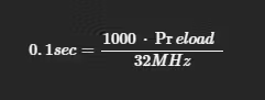
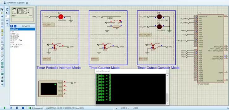
Table of Contents
STM32CubeMX Configuration:
- Open CubeMX & Create New Project Choose The Target MCU STM32F103C6 & Double-Click Its Name
- Go To The Clock Configuration & Set The System Clock To 32MHz
Configuration for the TIMER Periodic Interrupt Mode:
- Configure The GPIO Pins PB3 as Output Pin
- In the Categories tab, select the TIM3 & enable Internal Clock
- In the Parameter settings tab, set the (Prescaler=1000 & Counter Peroid 32000) The purpose of this settings is to generate a periodic time event with a 100ms interval
- In the NVIC settings tab, Enable TIM3 global Interrupt
Configuration for the Timer Counter Mode:
- In the Categories tab, select the TIM1 & enable ETR2 in “Clock Source” the clock source is an external pin (timer1 input pin ETR2) which is highlighted as PA12.
- In the Parameter settings tab, set the (Counter Mode =up & Counter Peroid=10 & Auto-reload preload= Enable)
- In the NVIC settings tab, Enable TIM1 update Interrupt
- Enable USART1 Module (Asynchronous Mode)
- Set the USART1 and USART2 communication parameters (baud rate = 9600, parity=NON, stop bits =1, and word length =8bits)
Configuration for the Timer Output Compare Mode:
- In the Categories tab, select the TIM2 & Enable Output Compare for Channel 2 and 4
- In the Parameter settings tab, set the (Prescaler=3200-1 & Counter Peroid 1000)
- In the Outpute Compare Channel 2 set the (Mode=Toggle on match & Pulse 200 & Output compare preload = Enable)
- In the Outpute Compare Channel 4 set the (Mode=Toggle on match & Pulse 400 & Output compare preload = Enable)
- Generate The Initialization Code & Open The Project In CubeIDE
STM32CubeIDE Configuration:
- Write The Application Layer Code
- stm32f1xx_it.c
- main.c
Proteus Configuration :
- Open Proteus & Create New Project and click next

- Click on Pick Device
- Search for STM32F103C6 & SW-SPDT(switch) & LED_RED & Button & RES
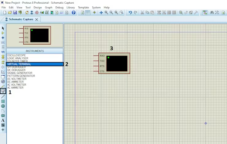
- Click on Virtual Instruments Mode then choose VIRTUAL TERMINAL
- Click on Terminal Mode then choose (DEFAULT & POWER & GROUND)
1 comment
[…] the advanced Timer functionality offered by the STM32 series. By harnessing the capabilities of STM32’s Timer peripherals, developers can significantly enhance the accuracy and efficiency of distance […]