
In this project, we’ll interface the TC72 Temperature Sensor with STM32 via SPI, ensuring accurate temperature readings with efficient data transfer.

Things used in this project
Software apps and online services:
1- STMicroelectronics STM32CubeMX
2- STMicroelectronics STM32CubeIDE
3- Proteus 8
Exploring Temperature Sensing with TC72 and STM32: SPI Interface Integration
This project aims to teach you about the Serial Peripheral Interface (SPI) communication protocol and how to interface the TC72 temperature sensor with an STM32 microcontroller. The TC72 is a digital temperature sensor that can provide highly accurate temperature readings with low power consumption, making it ideal for use in a variety of embedded applications.
TC72 Sensor Connection: SPI Bus and Chip Select Pin Usage:
According to the datasheet for the TC72 sensor, in order to establish a connection between the sensor and a microcontroller, it is necessary to connect the SPI bus lines, specifically the SCLK, MOSI, and MISO lines, between the two devices. The chip select (CS) pin must also be utilized to enable and disable the sensor during communication.
Configuring Microcontroller SPI Settings for TC72 Communication:
After establishing the connections, you will need to configure the SPI settings on the microcontroller, including the clock frequency, data order, and data frame size. Once the settings are configured, the microcontroller can send commands to the TC72 sensor to request temperature data. The sensor responds by providing the temperature value in a 16-bit data frame.
Temperature Data Reception and Processing on the Microcontroller:
The microcontroller will then receive the temperature data and perform any necessary calculations or conversions to display or use the temperature value. This process can be repeated as needed to continuously monitor the temperature using the TC72 sensor.
By following the step-by-step instructions provided in this project, you will learn how to configure the necessary settings, and develop code to read the temperature values from the sensor. this project will also include simulation on Proteus software.
STM32CubeMX Configuration:
- Open CubeMX & Create New Project Choose The Target MCU STM32F103C6 & Double-Click Its Name
- Go To The Clock Configuration & Set The System Clock To 8MHz
SPI Configuration:
- Configure The GPIO Pin PA4 as Output Pin (CSPin)
- In the Categories tab, select the SPI1 & Full-Duplex Master
UART Configuration:
- Enable USART1 Module (Asynchronous Mode)
- Set the USART1 communication parameters (baud rate = 9600, parity=NON, stop bits = 1, and word length =8bits)
- Generate The Initialization Code & Open The Project In CubeIDE
- Write The Application Layer Code
STM32CubeIDE Configuration :
In file name : main.c
#include "main.h"
#include <math.h>
#include <stdio.h>
#include <string.h>

#define ASSERT_CS()   (HAL_GPIO_WritePin(GPIOA,GPIO_PIN_4,GPIO_PIN_SET))
#define DEASSERT_CS() (HAL_GPIO_WritePin(GPIOA,GPIO_PIN_4,GPIO_PIN_RESET))

typedef struct {
  uint8_t lsb_temp;
  uint8_t msb_temp;
}tc72_t;

void floatToStr(float val , char data[])
{
  if (val<0)
  {
    *data='-';
    data++;
    val*=-1;
  }
  int intVal =val*100;
  data[5] = (intVal %10) +'0';
  intVal /=10;
  data[4] = (intVal %10) +'0';
  data[3] = '.';
  intVal /=10;
  data[2] = (intVal %10) +'0';
  intVal /=10;
  data[1] = (intVal %10) +'0';
  intVal /=10;
  data[0] = (intVal %10) +'0';
  intVal /=10;
}

int main(void)
{
  tc72_t  tc72;
  uint8_t TxBuf[10];
  uint8_t RxBuf[10];

      char  str [20];
      char  str2[20] ="temperature = ";
      float temp;
      int   x;
HAL_Init();
SystemClock_Config();
MX_GPIO_Init();
MX_SPI1_Init();
MX_USART1_UART_Init();

while (1)
  {
    TxBuf[0]=0x80;
    TxBuf[1]=0x00;

    ASSERT_CS();
    HAL_SPI_Transmit(&hspi1, TxBuf, 2, 100);
    DEASSERT_CS();

    TxBuf[0]=0x01;
    temp = 0.0f;

    ASSERT_CS();
    HAL_SPI_TransmitReceive(&hspi1, TxBuf, RxBuf, 4, 100);
    DEASSERT_CS();
          if(RxBuf[1]& (1<<6))
          {
            temp+=0.5f;
          }
          else if(RxBuf[1]& (1<<7))
          {
            temp+=0.25f;
          }

   TxBuf[0]=0x02;
   ASSERT_CS();
   HAL_SPI_TransmitReceive(&hspi1, TxBuf, RxBuf, 4, 100);
   DEASSERT_CS();

   tc72.msb_temp = RxBuf[1];
   tc72.lsb_temp = RxBuf[2];

   int16_t Temp_reg = tc72.msb_temp <<8 | tc72.lsb_temp;
   Temp_reg >>=7;
   x= ((signed char)(Temp_reg));
   temp+=x;

   floatToStr(temp,str);

   HAL_UART_Transmit(&huart1,(uint8_t*)str2, sizeof(str2), 100);
   HAL_UART_Transmit(&huart1,(uint8_t*)str, sizeof(str), 100);
   HAL_UART_Transmit(&huart1,(uint8_t*)&"\n\r",2, 2);
   HAL_Delay(1000);
 }}
Proteus Configuration :
- Open Proteus & Create New Project and click next

- Click on Pick Device
- Search for STM32F103C6 & TC72
- Click on Virtual Instrumets Mode then choose VIRTUAL TERMINAL & SPI DEBUGGER
- Click on Terminal Mode then choose (DEFAULT & POWER &GROUND)
- finally make the circuit below and start the simulation
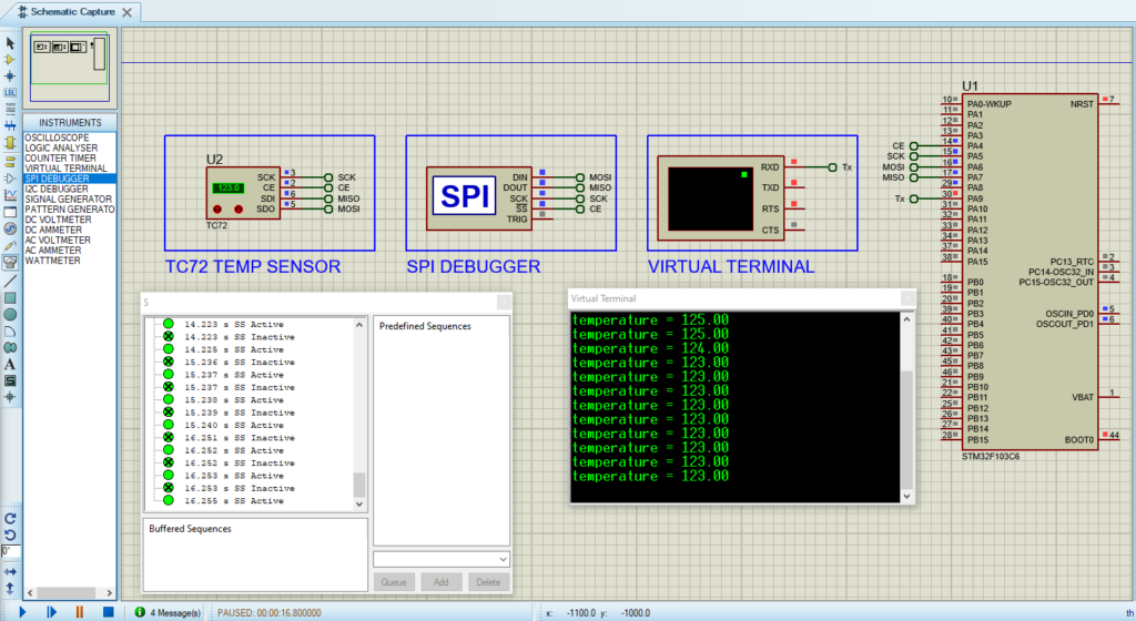
That’s all!
If you have any questions or suggestions don’t hesitate to leave a comment below