
This article covers interfacing STM32 with ST7735 color TFT display using SPI. You’ll learn about the required components, connections, and programming techniques to display graphics and text on the TFT screen.
Things used in this project
Software apps and online services:
1- STMicroelectronics STM32CubeMX
2- STMicroelectronics STM32CubeIDE
3- Proteus 8
Displaying Graphics and Text on ST7735 TFT LCD with STM32 Microcontroller:
This project involves interfacing STM32 with the ST7735 TFT display using SPI communication in Proteus simulation software. The purpose of this project is to demonstrate how to display graphics and text on the ST7735 display through interfacing STM32 with ST7735 TFT display using SPI.
ST7735 Display Module Overview: Features and Capabilities:
The ST7735 display is a small, color TFT LCD display module that supports a resolution of 128×160 pixels. It has an integrated controller that supports SPI communication protocol for transferring data to the display. The ST7735 display is capable of displaying up to 18-bit color depth, which means it can display up to 262,144 colors.
Configuring Pins for STM32 to ST7735 Display Interfacing:
To interface the STM32 microcontroller with the ST7735 display, we need to connect the SPI pins of the microcontroller to the corresponding pins of the display module. The SPI pins include MOSI (Master Output Slave Input), MISO (Master Input Slave Output), SCK (Serial Clock), and CS (Chip Select). We also need to connect the power and ground pins of the display module to the corresponding pins of the microcontroller.
Overall, this project provides example of how to interface an STM32 microcontroller with an ST7735 display using SPI communication protocol in a Proteus simulation environment.
STM32CubeMX Configuration:
- Open CubeMX & Create New Project Choose The Target MCU STM32F103C6 & Double-Click Its Name
- In the Categories tab, select the RCC High Speed Clock (HSE) to Crystal/Ceramic Resonator
- Go To The Clock Configuration & Set The System Clock To 72MHz
- Configure The GPIO Pins [PB12..PB15] as Output Pin
- In the Categories tab, select the SPI1 & Transmit Only Master
- In the Parameter settings tab, set the Prescaler (for baud Rate) to 16
- Generate The Initialization Code & Open The Project In CubeIDE
STM32CubeIDE Configuration :
- Write The Application Layer Code
- t7735_cfg.h
- ST7735.h & ST7735.c
/*
 * st7735_cfg.h
 *
 */

#ifndef ST7735_CFG_H_
#define ST7735_CFG_H_

#include "main.h"
#define ST7735_SPI_PORT hspi1 //hspi1, hspi2, hspi3...
//#define USE_SPI_DMA     //if used DMA for SPI bus

//#define ST7735_1_8_DEFAULT_ORIENTATION  // AliExpress/eBay 1.8" display, default orientation
#define ST7735S_1_8_DEFAULT_ORIENTATION   // WaveShare ST7735S-based 1.8" display, default orientation
//#define ST7735_1_44_DEFAULT_ORIENTATION   // 1.44" display, default orientation
//#define ST7735_MINI_DEFAULT_ORIENTATION   // mini 160x80 display (it's unlikely you want the default orientation)

//Port and pin connected signal 'RES' (reset) ST7735 display
#ifndef ST7735_RES_Pin
#define ST7735_RES_Pin      GPIO_PIN_12
#endif
#ifndef ST7735_RES_GPIO_Port
#define ST7735_RES_GPIO_Port  GPIOB
#endif
//Port and pin connected signal 'DC' (data or command) ST7735 display
#ifndef ST7735_DC_Pin
#define ST7735_DC_Pin       GPIO_PIN_13
#endif
#ifndef ST7735_DC_GPIO_Port
#define ST7735_DC_GPIO_Port   GPIOB
#endif
//Port and pin connected signal 'CS' (chip select) ST7735 display
#ifndef ST7735_CS_Pin
#define ST7735_CS_Pin       GPIO_PIN_14
#endif
#ifndef ST7735_CS_GPIO_Port
#define ST7735_CS_GPIO_Port   GPIOB
#endif
//Port and pin connected signal 'BL' (back light) ST7735 display
#ifndef ST7735_BL_Pin
#define ST7735_BL_Pin     GPIO_PIN_15
#endif
#ifndef ST7735_BL_GPIO_Port
#define ST7735_BL_GPIO_Port   GPIOB
#endif


#endif /* ST7735_CFG_H_ */
/*
 * ST7735.h
 *
 */

#ifndef ST7735_H_
#define ST7735_H_

#include "fonts.h"
#include "st7735_cfg.h"
#include <stdbool.h>

extern SPI_HandleTypeDef ST7735_SPI_PORT;

#define ST7735_MADCTL_MY  0x80
#define ST7735_MADCTL_MX  0x40
#define ST7735_MADCTL_MV  0x20
#define ST7735_MADCTL_RGB 0x00
#define ST7735_MADCTL_BGR 0x08

// AliExpress/eBay 1.8" display, default orientation
#ifdef ST7735_1_8_DEFAULT_ORIENTATION
#define ST7735_IS_160X128   1
#define ST7735_WIDTH        128
#define ST7735_HEIGHT       160
#define ST7735_XSTART       0
#define ST7735_YSTART       0
#define ST7735_DATA_ROTATION  (ST7735_MADCTL_MX | ST7735_MADCTL_MY)
#endif //ST7735_1_8_DEFAULT_ORIENTATION

// WaveShare ST7735S-based 1.8" display, default orientation
#ifdef ST7735S_1_8_DEFAULT_ORIENTATION
#define ST7735_IS_160X128     1
#define ST7735_WIDTH        128
#define ST7735_HEIGHT       160
#define ST7735_XSTART       2
#define ST7735_YSTART       1
#define ST7735_DATA_ROTATION  (ST7735_MADCTL_MX | ST7735_MADCTL_MY | ST7735_MADCTL_RGB)
#endif //ST7735S_1_8_DEFAULT_ORIENTATION

// 1.44" display, default orientation
#ifdef ST7735_1_44_DEFAULT_ORIENTATION
#define ST7735_IS_128X128     1
#define ST7735_WIDTH        128
#define ST7735_HEIGHT       128
#define ST7735_XSTART       2
#define ST7735_YSTART       3
//#define ST7735_VALUE_ROTATION 0
#define ST7735_DATA_ROTATION  (ST7735_MADCTL_MX | ST7735_MADCTL_MY | ST7735_MADCTL_BGR)
#endif //ST7735_1_44_DEFAULT_ORIENTATION

// mini 160x80 display (it's unlikely you want the default orientation)
#ifdef ST7735_MINI_DEFAULT_ORIENTATION
#define ST7735_IS_160X80    1
#define ST7735_XSTART       26
#define ST7735_YSTART       1
#define ST7735_WIDTH        80
#define ST7735_HEIGHT       160
//#define ST7735_VALUE_ROTATION 0
#define ST7735_DATA_ROTATION  (ST7735_MADCTL_MX | ST7735_MADCTL_MY | ST7735_MADCTL_BGR)
#endif //ST7735_MINI_DEFAULT_ORIENTATION
/****************************/

#define ST7735_NOP     0x00
#define ST7735_SWRESET 0x01
#define ST7735_RDDID   0x04
#define ST7735_RDDST   0x09

#define ST7735_SLPIN   0x10
#define ST7735_SLPOUT  0x11
#define ST7735_PTLON   0x12
#define ST7735_NORON   0x13

#define ST7735_INVOFF  0x20
#define ST7735_INVON   0x21
#define ST7735_DISPOFF 0x28
#define ST7735_DISPON  0x29
#define ST7735_CASET   0x2A
#define ST7735_RASET   0x2B
#define ST7735_RAMWR   0x2C
#define ST7735_RAMRD   0x2E

#define ST7735_PTLAR   0x30
#define ST7735_COLMOD  0x3A
#define ST7735_MADCTL  0x36

#define ST7735_FRMCTR1 0xB1
#define ST7735_FRMCTR2 0xB2
#define ST7735_FRMCTR3 0xB3
#define ST7735_INVCTR  0xB4
#define ST7735_DISSET5 0xB6

#define ST7735_PWCTR1  0xC0
#define ST7735_PWCTR2  0xC1
#define ST7735_PWCTR3  0xC2
#define ST7735_PWCTR4  0xC3
#define ST7735_PWCTR5  0xC4
#define ST7735_VMCTR1  0xC5

#define ST7735_RDID1   0xDA
#define ST7735_RDID2   0xDB
#define ST7735_RDID3   0xDC
#define ST7735_RDID4   0xDD

#define ST7735_PWCTR6  0xFC

#define ST7735_GMCTRP1 0xE0
#define ST7735_GMCTRN1 0xE1

// Color definitions
#define ST7735_BLACK   0x0000
#define ST7735_BLUE    0x001F
#define ST7735_RED     0xF800
#define ST7735_GREEN   0x07E0
#define ST7735_CYAN    0x07FF
#define ST7735_MAGENTA 0xF81F
#define ST7735_YELLOW  0xFFE0
#define ST7735_WHITE   0xFFFF

void ST7735_Backlight_On(void);
void ST7735_Backlight_Off(void);
void ST7735_Init(void);
void ST7735_DrawPixel(uint16_t x, uint16_t y, uint16_t color);
void ST7735_DrawString(uint16_t x, uint16_t y, const char* str, FontDef font, uint16_t color, uint16_t bgcolor);
void ST7735_FillRectangle(uint16_t x, uint16_t y, uint16_t w, uint16_t h, uint16_t color);
void ST7735_FillScreen(uint16_t color);
void ST7735_DrawImage(uint16_t x, uint16_t y, uint16_t w, uint16_t h, const uint16_t* data);
void ST7735_DrawTouchGFX(uint16_t x, uint16_t y, uint16_t w, uint16_t h, const uint16_t* data);
void ST7735_InvertColors(bool invert);
void ST7735_DrawCircle(int16_t x0, int16_t y0, int16_t r, uint16_t color);
void ST7735_DrawCircleHelper( int16_t x0, int16_t y0, int16_t r, uint8_t cornername, uint16_t color);
void ST7735_FillCircle(int16_t x0, int16_t y0, int16_t r, uint16_t color);
void ST7735_FillCircleHelper(int16_t x0, int16_t y0, int16_t r, uint8_t cornername, int16_t delta, uint16_t color);
void ST7735_DrawEllipse(int16_t x0, int16_t y0, int16_t rx, int16_t ry, uint16_t color);
void ST7735_FillEllipse(int16_t x0, int16_t y0, int16_t rx, int16_t ry, uint16_t color);
void ST7735_DrawRect(int16_t x, int16_t y, int16_t w, int16_t h, uint16_t color);
void ST7735_DrawRoundRect(int16_t x, int16_t y, int16_t w, int16_t h, int16_t r, uint16_t color);
void ST7735_FillRoundRect(int16_t x, int16_t y, int16_t w, int16_t h, int16_t r, uint16_t color);
void ST7735_DrawTriangle(int16_t x0, int16_t y0, int16_t x1, int16_t y1, int16_t x2, int16_t y2, uint16_t color);
void ST7735_FillTriangle( int16_t x0, int16_t y0, int16_t x1, int16_t y1, int16_t x2, int16_t y2, uint16_t color);
void ST7735_DrawLine(int16_t x0, int16_t y0, int16_t x1, int16_t y1, uint16_t color);
void ST7735_DrawFastVLine(int16_t x, int16_t y, int16_t h, uint16_t color);
void ST7735_DrawFastHLine(int16_t x, int16_t y, int16_t w, uint16_t color);
void ST7735_SetRotation(uint8_t m);
uint8_t ST7735_GetRotation(void);
int16_t ST7735_GetHeight(void);
int16_t ST7735_GetWidth(void);


#endif /* ST7735_H_ */
/*
 * ST773.c
 *
 */


#include "ST7735.h"
#include "stdlib.h"

#define TFT_BL_H()  HAL_GPIO_WritePin(ST7735_BL_GPIO_Port, ST7735_BL_Pin, GPIO_PIN_SET)
#define TFT_BL_L()  HAL_GPIO_WritePin(ST7735_BL_GPIO_Port, ST7735_BL_Pin, GPIO_PIN_RESET)
#define TFT_CS_H()  HAL_GPIO_WritePin(ST7735_CS_GPIO_Port, ST7735_CS_Pin, GPIO_PIN_SET)
#define TFT_CS_L()  HAL_GPIO_WritePin(ST7735_CS_GPIO_Port, ST7735_CS_Pin, GPIO_PIN_RESET)
#define TFT_DC_D()  HAL_GPIO_WritePin(ST7735_DC_GPIO_Port, ST7735_DC_Pin, GPIO_PIN_SET)
#define TFT_DC_C()  HAL_GPIO_WritePin(ST7735_DC_GPIO_Port, ST7735_DC_Pin, GPIO_PIN_RESET)
#define TFT_RES_H() HAL_GPIO_WritePin(ST7735_RES_GPIO_Port, ST7735_RES_Pin, GPIO_PIN_SET)
#define TFT_RES_L() HAL_GPIO_WritePin(ST7735_RES_GPIO_Port, ST7735_RES_Pin, GPIO_PIN_RESET)

#define ST7735_COLOR565(r, g, b) (((r & 0xF8) << 8) | ((g & 0xFC) << 3) | ((b & 0xF8) >> 3))
#define SWAP_INT16_T(a, b) { int16_t t = a; a = b; b = t; }
#define DELAY 0x80

#if defined(ST7735_1_8_DEFAULT_ORIENTATION) || defined(ST7735S_1_8_DEFAULT_ORIENTATION)
static uint8_t _data_rotation[4] = { ST7735_MADCTL_MX, ST7735_MADCTL_MY, ST7735_MADCTL_MV, ST7735_MADCTL_RGB };
#endif

#if defined(ST7735_1_44_DEFAULT_ORIENTATION) || defined(ST7735_MINI_DEFAULT_ORIENTATION)
static uint8_t _data_rotation[4] = { ST7735_MADCTL_MX, ST7735_MADCTL_MY, ST7735_MADCTL_MV, ST7735_MADCTL_BGR };
#endif

static uint8_t _value_rotation = 0;
static int16_t _height = ST7735_HEIGHT, _width = ST7735_WIDTH;
static uint8_t _xstart = ST7735_XSTART, _ystart = ST7735_YSTART;

// based on Adafruit ST7735 library for Arduino
static const uint8_t
init_cmds1[] = {                // Init for 7735R, part 1 (red or green tab)
      15,                       // 15 commands in list:
      ST7735_SWRESET, DELAY,    //  1: Software reset, 0 args, w/delay
      150,                      //     150 ms delay
      ST7735_SLPOUT, DELAY,   //  2: Out of sleep mode, 0 args, w/delay
      255,                      //     500 ms delay
      ST7735_FRMCTR1, 3,    //  3: Frame rate ctrl - normal mode, 3 args:
      0x01, 0x2C, 0x2D,         //     Rate = fosc/(1x2+40) * (LINE+2C+2D)
      ST7735_FRMCTR2, 3,      //  4: Frame rate control - idle mode, 3 args:
      0x01, 0x2C, 0x2D,         //     Rate = fosc/(1x2+40) * (LINE+2C+2D)
      ST7735_FRMCTR3, 6,      //  5: Frame rate ctrl - partial mode, 6 args:
      0x01, 0x2C, 0x2D,         //     Dot inversion mode
      0x01, 0x2C, 0x2D,         //     Line inversion mode
      ST7735_INVCTR, 1,     //  6: Display inversion ctrl, 1 arg, no delay:
      0x07,                     //     No inversion
      ST7735_PWCTR1, 3,     //  7: Power control, 3 args, no delay:
      0xA2,
      0x02,                     //     -4.6V
      0x84,                     //     AUTO mode
      ST7735_PWCTR2, 1,     //  8: Power control, 1 arg, no delay:
      0xC5,                     //     VGH25 = 2.4C VGSEL = -10 VGH = 3 * AVDD
      ST7735_PWCTR3, 2,     //  9: Power control, 2 args, no delay:
      0x0A,                     //     Opamp current small
      0x00,                     //     Boost frequency
      ST7735_PWCTR4, 2,     // 10: Power control, 2 args, no delay:
      0x8A,                     //     BCLK/2, Opamp current small & Medium low
      0x2A,
      ST7735_PWCTR5, 2,     // 11: Power control, 2 args, no delay:
      0x8A, 0xEE,
      ST7735_VMCTR1, 1,     // 12: Power control, 1 arg, no delay:
      0x0E,
      ST7735_INVOFF, 0,     // 13: Don't invert display, no args, no delay
      ST7735_MADCTL, 1,     // 14: Memory access control (directions), 1 arg:
      ST7735_DATA_ROTATION,     //     row addr/col addr, bottom to top refresh
      ST7735_COLMOD, 1,     // 15: set color mode, 1 arg, no delay:
      0x05},                  //     16-bit color

#if (defined(ST7735_IS_128X128) || defined(ST7735_IS_160X128))
init_cmds2[] = {            // Init for 7735R, part 2 (1.44" display)
    2,                  //  2 commands in list:
    ST7735_CASET, 4,    //  1: Column addr set, 4 args, no delay:
    0x00, 0x00,         //     XSTART = 0
    0x00, 0x7F,         //     XEND = 127
    ST7735_RASET, 4,    //  2: Row addr set, 4 args, no delay:
    0x00, 0x00,         //     XSTART = 0
    0x00, 0x7F },       //     XEND = 127
#endif // ST7735_IS_128X128

#ifdef ST7735_IS_160X80
init_cmds2[] = {          // Init for 7735S, part 2 (160x80 display)
    3,                          //  3 commands in list:
    ST7735_CASET, 4,        //  1: Column addr set, 4 args, no delay:
    0x00, 0x00,               //     XSTART = 0
    0x00, 0x4F,               //     XEND = 79
    ST7735_RASET, 4,        //  2: Row addr set, 4 args, no delay:
    0x00, 0x00,               //     XSTART = 0
    0x00, 0x9F ,              //     XEND = 159
    ST7735_INVON, 0 },        //  3: Invert colors
#endif

init_cmds3[] = {                // Init for 7735R, part 3 (red or green tab)
    4,                          //  4 commands in list:
    ST7735_GMCTRP1, 16,     //  1: Magical unicorn dust, 16 args, no delay:
    0x02, 0x1c, 0x07, 0x12,
    0x37, 0x32, 0x29, 0x2d,
    0x29, 0x25, 0x2B, 0x39,
    0x00, 0x01, 0x03, 0x10,
    ST7735_GMCTRN1, 16,     //  2: Sparkles and rainbows, 16 args, no delay:
    0x03, 0x1d, 0x07, 0x06,
    0x2E, 0x2C, 0x29, 0x2D,
    0x2E, 0x2E, 0x37, 0x3F,
    0x00, 0x00, 0x02, 0x10,
    ST7735_NORON, DELAY,    //  3: Normal display on, no args, w/delay
    10,                       //     10 ms delay
    ST7735_DISPON, DELAY,     //  4: Main screen turn on, no args w/delay
    100 };                    //     100 ms delay

static void ST7735_GPIO_Init(void);
static void ST7735_WriteCommand(uint8_t cmd);
static void ST7735_WriteData(uint8_t* buff, size_t buff_size);
static void ST7735_ExecuteCommandList(const uint8_t *addr);
static void ST7735_SetAddressWindow(uint8_t x0, uint8_t y0, uint8_t x1, uint8_t y1);
static void ST7735_WriteChar(uint16_t x, uint16_t y, char ch, FontDef font, uint16_t color, uint16_t bgcolor);

static void ST7735_GPIO_Init(void)
{
//  GPIO_InitTypeDef GPIO_InitStruct = {0};
//
//  /* GPIO Ports Clock Enable */
//  __HAL_RCC_GPIOB_CLK_ENABLE();
//
//  /*Configure GPIO pin Output Level */
//  HAL_GPIO_WritePin(GPIOB, ST7735_RES_Pin|ST7735_DC_Pin|ST7735_CS_Pin|ST7735_BL_Pin, GPIO_PIN_RESET);
//
//  /*Configure GPIO pins : ST7735_RES_Pin ST7735_DC_Pin ST7735_CS_Pin ST7735_BL_Pin */
//  GPIO_InitStruct.Pin = ST7735_RES_Pin|ST7735_DC_Pin|ST7735_CS_Pin|ST7735_BL_Pin;
//  GPIO_InitStruct.Mode = GPIO_MODE_OUTPUT_PP;
//  GPIO_InitStruct.Pull = GPIO_NOPULL;
//  GPIO_InitStruct.Speed = GPIO_SPEED_FREQ_LOW;
//  HAL_GPIO_Init(GPIOB, &GPIO_InitStruct);
}

static void ST7735_Reset()
{
  TFT_RES_L();
  HAL_Delay(20);
  TFT_RES_H();
}

static void ST7735_WriteCommand(uint8_t cmd)
{
  TFT_DC_C();
#ifdef USE_SPI_DMA
  HAL_SPI_Transmit_DMA(&ST7735_SPI_PORT, &cmd, sizeof(cmd));
  //while(hspi1.State == HAL_SPI_STATE_BUSY_TX);
#else
  HAL_SPI_Transmit(&ST7735_SPI_PORT, &cmd, sizeof(cmd), HAL_MAX_DELAY);
#endif
}

static void ST7735_WriteData(uint8_t* buff, size_t buff_size)
{
  TFT_DC_D();
#ifdef USE_SPI_DMA
  HAL_SPI_Transmit_DMA(&ST7735_SPI_PORT, buff, buff_size);
  while(hspi1.State == HAL_SPI_STATE_BUSY_TX);

#else
  HAL_SPI_Transmit(&ST7735_SPI_PORT, buff, buff_size, HAL_MAX_DELAY);
#endif
}

static void ST7735_ExecuteCommandList(const uint8_t *addr)
{
    uint8_t numCommands, numArgs;
    uint16_t ms;

    numCommands = *addr++;
    while(numCommands--)
    {
      uint8_t cmd = *addr++;
        ST7735_WriteCommand(cmd);

        numArgs = *addr++;
        // If high bit set, delay follows args
        ms = numArgs & DELAY;
        numArgs &= ~DELAY;
        if(numArgs)
        {
            ST7735_WriteData((uint8_t*)addr, numArgs);
            addr += numArgs;
        }

        if(ms)
        {
            ms = *addr++;
            if(ms == 255) ms = 500;
            HAL_Delay(ms);
        }
    }
}

static void ST7735_SetAddressWindow(uint8_t x0, uint8_t y0, uint8_t x1, uint8_t y1)
{
    // column address set
    ST7735_WriteCommand(ST7735_CASET);
    uint8_t data[] = { 0x00, x0 + _xstart, 0x00, x1 + _xstart };
    ST7735_WriteData(data, sizeof(data));

    // row address set
    ST7735_WriteCommand(ST7735_RASET);
    data[1] = y0 + _ystart;
    data[3] = y1 + _ystart;
    ST7735_WriteData(data, sizeof(data));

    // write to RAM
    ST7735_WriteCommand(ST7735_RAMWR);
}

static void ST7735_WriteChar(uint16_t x, uint16_t y, char ch, FontDef font, uint16_t color, uint16_t bgcolor)
{
    uint32_t i, b, j;

    ST7735_SetAddressWindow(x, y, x+font.width-1, y+font.height-1);

    for(i = 0; i < font.height; i++)
    {
        b = font.data[(ch - 32) * font.height + i];
        for(j = 0; j < font.width; j++)
        {
            if((b << j) & 0x8000)
            {
                uint8_t data[] = { color >> 8, color & 0xFF };
                ST7735_WriteData(data, sizeof(data));
            }
            else
            {
                uint8_t data[] = { bgcolor >> 8, bgcolor & 0xFF };
                ST7735_WriteData(data, sizeof(data));
            }
        }
    }
}

void ST7735_Init()
{
  ST7735_GPIO_Init();
  TFT_CS_L();
    ST7735_Reset();
    ST7735_ExecuteCommandList(init_cmds1);
    ST7735_ExecuteCommandList(init_cmds2);
    ST7735_ExecuteCommandList(init_cmds3);
    TFT_CS_H();
}

void ST7735_DrawPixel(uint16_t x, uint16_t y, uint16_t color)
{
    if((x >= _width) || (y >= _height))
        return;

    TFT_CS_L();

    ST7735_SetAddressWindow(x, y, x+1, y+1);
    uint8_t data[] = { color >> 8, color & 0xFF };
    ST7735_WriteData(data, sizeof(data));

    TFT_CS_H();
}

void ST7735_DrawString(uint16_t x, uint16_t y, const char* str, FontDef font, uint16_t color, uint16_t bgcolor)
{
  TFT_CS_L();

    while(*str)
    {
        if(x + font.width >= _width)
        {
            x = 0;
            y += font.height;
            if(y + font.height >= _height)
            {
                break;
            }

            if(*str == ' ')
            {
                // skip spaces in the beginning of the new line
                str++;
                continue;
            }
        }

        ST7735_WriteChar(x, y, *str, font, color, bgcolor);
        x += font.width;
        str++;
    }
    TFT_CS_H();
}

void ST7735_FillRectangle(uint16_t x, uint16_t y, uint16_t w, uint16_t h, uint16_t color)
{
    // clipping
    if((x >= _width) || (y >= _height)) return;
    if((x + w - 1) >= _width) w = _width - x;
    if((y + h - 1) >= _height) h = _height - y;

    TFT_CS_L();
    ST7735_SetAddressWindow(x, y, x+w-1, y+h-1);

    uint8_t data[] = { color >> 8, color & 0xFF };
    TFT_DC_D();
    for(y = h; y > 0; y--)
    {
        for(x = w; x > 0; x--)
        {
#ifdef USE_SPI_DMA
          HAL_SPI_Transmit_DMA(&ST7735_SPI_PORT, data, sizeof(data));
          //while(hspi1.State == HAL_SPI_STATE_BUSY_TX);
#else
          HAL_SPI_Transmit(&ST7735_SPI_PORT, data, sizeof(data), HAL_MAX_DELAY);
#endif
        }
    }
    TFT_CS_H();
}

void ST7735_FillScreen(uint16_t color)
{
    ST7735_FillRectangle(0, 0, _width, _height, color);
}

void ST7735_DrawImage(uint16_t x, uint16_t y, uint16_t w, uint16_t h, const uint16_t* data)
{
    if((x >= _width) || (y >= _height)) return;
    if((x + w - 1) >= _width) return;
    if((y + h - 1) >= _height) return;

    TFT_CS_L();
    ST7735_SetAddressWindow(x, y, x+w-1, y+h-1);
    ST7735_WriteData((uint8_t*)data, sizeof(uint16_t)*w*h);
    TFT_CS_H();
}

void ST7735_DrawTouchGFX(uint16_t x, uint16_t y, uint16_t w, uint16_t h, const uint16_t* data)
{
    if((x >= _width) || (y >= _height)) return;
    if((x + w - 1) >= _width) return;
    if((y + h - 1) >= _height) return;

    TFT_CS_L();
    ST7735_SetAddressWindow(x, y, x+w-1, y+h-1);

    uint32_t size = w * h;
    uint8_t colorBytes[size][2];

    for (uint32_t i = 0; i < size; i++)
  {
    colorBytes[i][0] = (*data & 0xFF00) >> 8;
    colorBytes[i][1] = *data & 0x00FF;
    data++;
  }

    TFT_DC_D();
  ST7735_WriteData((uint8_t*) &colorBytes, size * 2);
    TFT_CS_H();
}

void ST7735_InvertColors(bool invert)
{
  TFT_CS_L();
    ST7735_WriteCommand(invert ? ST7735_INVON : ST7735_INVOFF);
    TFT_CS_H();
}

void ST7735_Backlight_On(void)
{
  TFT_BL_H();
}

void ST7735_Backlight_Off(void)
{
  TFT_BL_L();
}

/***************************************************************************************
** Function name:           drawCircle
** Description:             Draw a circle outline
***************************************************************************************/
void ST7735_DrawCircle(int16_t x0, int16_t y0, int16_t r, uint16_t color)
{
  int16_t f = 1 - r;
  int16_t ddF_x = 1;
  int16_t ddF_y = - r - r;
  int16_t x = 0;

  ST7735_DrawPixel(x0 + r, y0  , color);
  ST7735_DrawPixel(x0 - r, y0  , color);
  ST7735_DrawPixel(x0  , y0 - r, color);
  ST7735_DrawPixel(x0  , y0 + r, color);

  while (x < r)
  {
    if (f >= 0)
    {
      r--;
      ddF_y += 2;
      f += ddF_y;
    }
    x++;
    ddF_x += 2;
    f += ddF_x;

    ST7735_DrawPixel(x0 + x, y0 + r, color);
    ST7735_DrawPixel(x0 - x, y0 + r, color);
    ST7735_DrawPixel(x0 - x, y0 - r, color);
    ST7735_DrawPixel(x0 + x, y0 - r, color);

    ST7735_DrawPixel(x0 + r, y0 + x, color);
    ST7735_DrawPixel(x0 - r, y0 + x, color);
    ST7735_DrawPixel(x0 - r, y0 - x, color);
    ST7735_DrawPixel(x0 + r, y0 - x, color);
  }
}

/***************************************************************************************
** Function name:           drawCircleHelper
** Description:             Support function for circle drawing
***************************************************************************************/
void ST7735_DrawCircleHelper( int16_t x0, int16_t y0, int16_t r, uint8_t cornername, uint16_t color)
{
  int16_t f     = 1 - r;
  int16_t ddF_x = 1;
  int16_t ddF_y = -2 * r;
  int16_t x     = 0;

  while (x < r)
  {
    if (f >= 0)
    {
      r--;
      ddF_y += 2;
      f     += ddF_y;
    }
    x++;
    ddF_x += 2;
    f     += ddF_x;
    if (cornername & 0x8)
    {
      ST7735_DrawPixel(x0 - r, y0 + x, color);
      ST7735_DrawPixel(x0 - x, y0 + r, color);
    }
    if (cornername & 0x4)
    {
      ST7735_DrawPixel(x0 + x, y0 + r, color);
      ST7735_DrawPixel(x0 + r, y0 + x, color);
    }
    if (cornername & 0x2)
    {
      ST7735_DrawPixel(x0 + r, y0 - x, color);
      ST7735_DrawPixel(x0 + x, y0 - r, color);
    }
    if (cornername & 0x1)
    {
      ST7735_DrawPixel(x0 - x, y0 - r, color);
      ST7735_DrawPixel(x0 - r, y0 - x, color);
    }

  }
}

/***************************************************************************************
** Function name:           fillCircle
** Description:             draw a filled circle
***************************************************************************************/
void ST7735_FillCircle(int16_t x0, int16_t y0, int16_t r, uint16_t color)
{
  ST7735_DrawFastVLine(x0, y0 - r, r + r + 1, color);
  ST7735_FillCircleHelper(x0, y0, r, 3, 0, color);
}

/***************************************************************************************
** Function name:           fillCircleHelper
** Description:             Support function for filled circle drawing
***************************************************************************************/
// Used to do circles and roundrects
void ST7735_FillCircleHelper(int16_t x0, int16_t y0, int16_t r, uint8_t cornername, int16_t delta, uint16_t color)
{
  int16_t f     = 1 - r;
  int16_t ddF_x = 1;
  int16_t ddF_y = -r - r;
  int16_t x     = 0;

  delta++;
  while (x < r)
  {
    if (f >= 0)
    {
      r--;
      ddF_y += 2;
      f     += ddF_y;
    }
    x++;
    ddF_x += 2;
    f     += ddF_x;

    if (cornername & 0x1)
    {
      ST7735_DrawFastVLine(x0 + x, y0 - r, r + r + delta, color);
      ST7735_DrawFastVLine(x0 + r, y0 - x, x + x + delta, color);
    }
    if (cornername & 0x2)
    {
      ST7735_DrawFastVLine(x0 - x, y0 - r, r + r + delta, color);
      ST7735_DrawFastVLine(x0 - r, y0 - x, x + x + delta, color);
    }
  }
}

/***************************************************************************************
** Function name:           drawEllipse
** Description:             Draw a ellipse outline
***************************************************************************************/
void ST7735_DrawEllipse(int16_t x0, int16_t y0, int16_t rx, int16_t ry, uint16_t color)
{
  if (rx < 2) return;
  if (ry < 2) return;
  int16_t x, y;
  int32_t rx2 = rx * rx;
  int32_t ry2 = ry * ry;
  int32_t fx2 = 4 * rx2;
  int32_t fy2 = 4 * ry2;
  int32_t s;

  for (x = 0, y = ry, s = 2 * ry2 + rx2 * (1-2 * ry); ry2 * x <= rx2 * y; x++)
  {
    ST7735_DrawPixel(x0 + x, y0 + y, color);
    ST7735_DrawPixel(x0 - x, y0 + y, color);
    ST7735_DrawPixel(x0 - x, y0 - y, color);
    ST7735_DrawPixel(x0 + x, y0 - y, color);
    if (s >= 0)
    {
      s += fx2 * (1 - y);
      y--;
    }
    s += ry2 * ((4 * x) + 6);
  }

  for (x = rx, y = 0, s = 2 * rx2 + ry2 * (1 - 2 * rx); rx2 * y <= ry2 * x; y++)
  {
    ST7735_DrawPixel(x0 + x, y0 + y, color);
    ST7735_DrawPixel(x0 - x, y0 + y, color);
    ST7735_DrawPixel(x0 - x, y0 - y, color);
    ST7735_DrawPixel(x0 + x, y0 - y, color);
  if (s >= 0)
  {
    s += fy2 * (1 - x);
    x--;
  }
  s += rx2 * ((4 * y) + 6);
  }
}

/***************************************************************************************
** Function name:           fillEllipse
** Description:             draw a filled ellipse
***************************************************************************************/
void ST7735_FillEllipse(int16_t x0, int16_t y0, int16_t rx, int16_t ry, uint16_t color)
{
  if (rx < 2) return;
  if (ry < 2) return;
  int16_t x, y;
  int32_t rx2 = rx * rx;
  int32_t ry2 = ry * ry;
  int32_t fx2 = 4 * rx2;
  int32_t fy2 = 4 * ry2;
  int32_t s;

  for (x = 0, y = ry, s = 2 * ry2 + rx2 * (1 - 2 * ry); ry2 * x <= rx2 * y; x++)
  {
    ST7735_DrawFastHLine(x0 - x, y0 - y, x + x + 1, color);
    ST7735_DrawFastHLine(x0 - x, y0 + y, x + x + 1, color);

    if (s >= 0)
    {
      s += fx2 * (1 - y);
      y--;
    }
    s += ry2 * ((4 * x) + 6);
  }

  for (x = rx, y = 0, s = 2 * rx2 + ry2 * (1 - 2 * rx); rx2 * y <= ry2 * x; y++)
  {
    ST7735_DrawFastHLine(x0 - x, y0 - y, x + x + 1, color);
    ST7735_DrawFastHLine(x0 - x, y0 + y, x + x + 1, color);

    if (s >= 0)
    {
      s += fy2 * (1 - x);
      x--;
    }
    s += rx2 * ((4 * y) + 6);
  }

}

/***************************************************************************************
** Function name:           drawRect
** Description:             Draw a rectangle outline
***************************************************************************************/
// Draw a rectangle
void ST7735_DrawRect(int16_t x, int16_t y, int16_t w, int16_t h, uint16_t color)
{
  ST7735_DrawFastHLine(x, y, w, color);
  ST7735_DrawFastHLine(x, y + h - 1, w, color);
  ST7735_DrawFastVLine(x, y, h, color);
  ST7735_DrawFastVLine(x + w - 1, y, h, color);
}

/***************************************************************************************
** Function name:           drawRoundRect
** Description:             Draw a rounded corner rectangle outline
***************************************************************************************/
// Draw a rounded rectangle
void ST7735_DrawRoundRect(int16_t x, int16_t y, int16_t w, int16_t h, int16_t r, uint16_t color)
{
  // smarter version
  ST7735_DrawFastHLine(x + r  , y    , w - r - r, color); // Top
  ST7735_DrawFastHLine(x + r  , y + h - 1, w - r - r, color); // Bottom
  ST7735_DrawFastVLine(x    , y + r  , h - r - r, color); // Left
  ST7735_DrawFastVLine(x + w - 1, y + r  , h - r - r, color); // Right
  // draw four corners
  ST7735_DrawCircleHelper(x + r    , y + r    , r, 1, color);
  ST7735_DrawCircleHelper(x + r    , y + h - r - 1, r, 8, color);
  ST7735_DrawCircleHelper(x + w - r - 1, y + r    , r, 2, color);
  ST7735_DrawCircleHelper(x + w - r - 1, y + h - r - 1, r, 4, color);
}

/***************************************************************************************
** Function name:           fillRoundRect
** Description:             Draw a rounded corner filled rectangle
***************************************************************************************/
// Fill a rounded rectangle
void ST7735_FillRoundRect(int16_t x, int16_t y, int16_t w, int16_t h, int16_t r, uint16_t color)
{
  // smarter version
  ST7735_FillRectangle(x + r, y, w - r - r, h, color);

  // draw four corners
  ST7735_FillCircleHelper(x + w - r - 1, y + r, r, 1, h - r - r - 1, color);
  ST7735_FillCircleHelper(x + r    , y + r, r, 2, h - r - r - 1, color);
}

/***************************************************************************************
** Function name:           drawTriangle
** Description:             Draw a triangle outline using 3 arbitrary points
***************************************************************************************/
// Draw a triangle
void ST7735_DrawTriangle(int16_t x0, int16_t y0, int16_t x1, int16_t y1, int16_t x2, int16_t y2, uint16_t color)
{
  ST7735_DrawLine(x0, y0, x1, y1, color);
  ST7735_DrawLine(x1, y1, x2, y2, color);
  ST7735_DrawLine(x2, y2, x0, y0, color);
}

/***************************************************************************************
** Function name:           fillTriangle
** Description:             Draw a filled triangle using 3 arbitrary points
***************************************************************************************/
// Fill a triangle - original Adafruit function works well and code footprint is small
void ST7735_FillTriangle( int16_t x0, int16_t y0, int16_t x1, int16_t y1, int16_t x2, int16_t y2, uint16_t color)
{
  int16_t a, b, y, last;

  // Sort coordinates by Y order (y2 >= y1 >= y0)
  if (y0 > y1)
  {
    SWAP_INT16_T(y0, y1); SWAP_INT16_T(x0, x1);
  }

  if (y1 > y2)
  {
    SWAP_INT16_T(y2, y1); SWAP_INT16_T(x2, x1);
  }

  if (y0 > y1)
  {
    SWAP_INT16_T(y0, y1); SWAP_INT16_T(x0, x1);
  }

  if (y0 == y2)
  { // Handle awkward all-on-same-line case as its own thing
    a = b = x0;
    if (x1 < a)      a = x1;
    else if (x1 > b) b = x1;
    if (x2 < a)      a = x2;
    else if (x2 > b) b = x2;
    ST7735_DrawFastHLine(a, y0, b - a + 1, color);
    return;
  }

  int16_t
  dx01 = x1 - x0,
  dy01 = y1 - y0,
  dx02 = x2 - x0,
  dy02 = y2 - y0,
  dx12 = x2 - x1,
  dy12 = y2 - y1,
  sa   = 0,
  sb   = 0;

  // For upper part of triangle, find scanline crossings for segments
  // 0-1 and 0-2.  If y1=y2 (flat-bottomed triangle), the scanline y1
  // is included here (and second loop will be skipped, avoiding a /0
  // error there), otherwise scanline y1 is skipped here and handled
  // in the second loop...which also avoids a /0 error here if y0=y1
  // (flat-topped triangle).
  if (y1 == y2) last = y1;  // Include y1 scanline
  else         last = y1 - 1; // Skip it

  for (y = y0; y <= last; y++)
  {
    a   = x0 + sa / dy01;
    b   = x0 + sb / dy02;
    sa += dx01;
    sb += dx02;

    if (a > b) SWAP_INT16_T(a, b);
    ST7735_DrawFastHLine(a, y, b - a + 1, color);
  }

  // For lower part of triangle, find scanline crossings for segments
  // 0-2 and 1-2.  This loop is skipped if y1=y2.
  sa = dx12 * (y - y1);
  sb = dx02 * (y - y0);
  for (; y <= y2; y++)
  {
    a   = x1 + sa / dy12;
    b   = x0 + sb / dy02;
    sa += dx12;
    sb += dx02;

    if (a > b) SWAP_INT16_T(a, b);
    ST7735_DrawFastHLine(a, y, b - a + 1, color);
  }
}

/***************************************************************************************
** Function name:           drawLine
** Description:             draw a line between 2 arbitrary points
***************************************************************************************/

// Slower but more compact line drawing function
void ST7735_DrawLine(int16_t x0, int16_t y0, int16_t x1, int16_t y1, uint16_t color)
{
  int16_t steep = abs(y1 - y0) > abs(x1 - x0);
  if (steep)
  {
    SWAP_INT16_T(x0, y0);
    SWAP_INT16_T(x1, y1);
  }

  if (x0 > x1)
  {
    SWAP_INT16_T(x0, x1);
    SWAP_INT16_T(y0, y1);
  }

  int16_t dx, dy;
  dx = x1 - x0;
  dy = abs(y1 - y0);

  int16_t err = dx / 2;
  int16_t ystep;

  if (y0 < y1)
  {
    ystep = 1;
  }
  else
  {
    ystep = -1;
  }

  for (; x0<=x1; x0++)
  {
    if (steep)
    {
      ST7735_DrawPixel(y0, x0, color);
    }
    else
    {
      ST7735_DrawPixel(x0, y0, color);
    }
    err -= dy;
    if (err < 0)
    {
      y0 += ystep;
      err += dx;
    }
  }
}

/***************************************************************************************
** Function name:           drawFastVLine
** Description:             draw a vertical line
***************************************************************************************/
void ST7735_DrawFastVLine(int16_t x, int16_t y, int16_t h, uint16_t color)
{
  // Rudimentary clipping
  if ((x >= _width) || (y >= _height)) return;
  if ((y + h - 1) >= _height) h = _height - y;

  ST7735_DrawLine(x, y, x, y + h - 1, color);
}

/***************************************************************************************
** Function name:           drawFastHLine
** Description:             draw a horizontal line
***************************************************************************************/
void ST7735_DrawFastHLine(int16_t x, int16_t y, int16_t w, uint16_t color)
{
  // Rudimentary clipping
  if ((x >= _width) || (y >= _height)) return;
  if ((x + w - 1) >= _width)  w = _width - x;

  ST7735_DrawLine(x, y, x + w - 1, y, color);
}

/***************************************************************************************
** Function name:           setRotation
** Description:             rotate the screen orientation m = 0-3
***************************************************************************************/
void ST7735_SetRotation(uint8_t m)
{
  _value_rotation = m % 4;

  TFT_CS_L();

  ST7735_WriteCommand(ST7735_MADCTL);

  switch (_value_rotation)
  {
    case 0:
    {
      uint8_t d_r = (_data_rotation[0] | _data_rotation[1] | _data_rotation[3]);
      ST7735_WriteData(&d_r, sizeof(d_r));
        _width  = ST7735_WIDTH;
        _height = ST7735_HEIGHT;
        _xstart = ST7735_XSTART;
    _ystart = ST7735_YSTART;
    }
     break;
    case 1:
    {
      uint8_t d_r = (_data_rotation[1] | _data_rotation[2] | _data_rotation[3]);
      ST7735_WriteData(&d_r, sizeof(d_r));
      _width  = ST7735_HEIGHT;
      _height = ST7735_WIDTH;
      _xstart = ST7735_YSTART;
      _ystart = ST7735_XSTART;
    }
      break;
    case 2:
    {
      uint8_t d_r = _data_rotation[3];
      ST7735_WriteData(&d_r, sizeof(d_r));
      _width  = ST7735_WIDTH;
      _height = ST7735_HEIGHT;
      _xstart = ST7735_XSTART;
      _ystart = ST7735_YSTART;
    }
      break;
    case 3:
    {
      uint8_t d_r = (_data_rotation[0] | _data_rotation[2] | _data_rotation[3]);
      ST7735_WriteData(&d_r, sizeof(d_r));
      _width  = ST7735_HEIGHT;
      _height = ST7735_WIDTH;
      _xstart = ST7735_YSTART;
      _ystart = ST7735_XSTART;
    }
      break;
  }
  TFT_CS_H();
}

uint8_t ST7735_GetRotation(void)
{
  return _value_rotation;
}

int16_t ST7735_GetHeight(void)
{
  return _height;
}

int16_t ST7735_GetWidth(void)
{
  return _width;
}
- fonts.h & fonts.c
- testimg.h
- main.c
/*
 * fonts.h
 */

#ifndef FONTS_H_
#define FONTS_H_

#include <stdint.h>

typedef struct {
    const uint8_t width;
    uint8_t height;
    const uint16_t *data;
} FontDef;


extern FontDef Font_7x10;
extern FontDef Font_11x18;
extern FontDef Font_16x26;


#endif /* FONTS_H_ */
/*
 * fonts.c
 *
 */

#include "fonts.h"

static const uint16_t Font7x10 [] = {
0x0000, 0x0000, 0x0000, 0x0000, 0x0000, 0x0000, 0x0000, 0x0000, 0x0000, 0x0000,  // sp
0x1000, 0x1000, 0x1000, 0x1000, 0x1000, 0x1000, 0x0000, 0x1000, 0x0000, 0x0000,  // !
0x2800, 0x2800, 0x2800, 0x0000, 0x0000, 0x0000, 0x0000, 0x0000, 0x0000, 0x0000,  // "
0x2400, 0x2400, 0x7C00, 0x2400, 0x4800, 0x7C00, 0x4800, 0x4800, 0x0000, 0x0000,  // #
0x3800, 0x5400, 0x5000, 0x3800, 0x1400, 0x5400, 0x5400, 0x3800, 0x1000, 0x0000,  // $
0x2000, 0x5400, 0x5800, 0x3000, 0x2800, 0x5400, 0x1400, 0x0800, 0x0000, 0x0000,  // %
0x1000, 0x2800, 0x2800, 0x1000, 0x3400, 0x4800, 0x4800, 0x3400, 0x0000, 0x0000,  // &
0x1000, 0x1000, 0x1000, 0x0000, 0x0000, 0x0000, 0x0000, 0x0000, 0x0000, 0x0000,  // '
0x0800, 0x1000, 0x2000, 0x2000, 0x2000, 0x2000, 0x2000, 0x2000, 0x1000, 0x0800,  // (
0x2000, 0x1000, 0x0800, 0x0800, 0x0800, 0x0800, 0x0800, 0x0800, 0x1000, 0x2000,  // )
0x1000, 0x3800, 0x1000, 0x2800, 0x0000, 0x0000, 0x0000, 0x0000, 0x0000, 0x0000,  // *
0x0000, 0x0000, 0x1000, 0x1000, 0x7C00, 0x1000, 0x1000, 0x0000, 0x0000, 0x0000,  // +
0x0000, 0x0000, 0x0000, 0x0000, 0x0000, 0x0000, 0x0000, 0x1000, 0x1000, 0x1000,  // ,
0x0000, 0x0000, 0x0000, 0x0000, 0x0000, 0x3800, 0x0000, 0x0000, 0x0000, 0x0000,  // -
0x0000, 0x0000, 0x0000, 0x0000, 0x0000, 0x0000, 0x0000, 0x1000, 0x0000, 0x0000,  // .
0x0800, 0x0800, 0x1000, 0x1000, 0x1000, 0x1000, 0x2000, 0x2000, 0x0000, 0x0000,  // /
0x3800, 0x4400, 0x4400, 0x5400, 0x4400, 0x4400, 0x4400, 0x3800, 0x0000, 0x0000,  // 0
0x1000, 0x3000, 0x5000, 0x1000, 0x1000, 0x1000, 0x1000, 0x1000, 0x0000, 0x0000,  // 1
0x3800, 0x4400, 0x4400, 0x0400, 0x0800, 0x1000, 0x2000, 0x7C00, 0x0000, 0x0000,  // 2
0x3800, 0x4400, 0x0400, 0x1800, 0x0400, 0x0400, 0x4400, 0x3800, 0x0000, 0x0000,  // 3
0x0800, 0x1800, 0x2800, 0x2800, 0x4800, 0x7C00, 0x0800, 0x0800, 0x0000, 0x0000,  // 4
0x7C00, 0x4000, 0x4000, 0x7800, 0x0400, 0x0400, 0x4400, 0x3800, 0x0000, 0x0000,  // 5
0x3800, 0x4400, 0x4000, 0x7800, 0x4400, 0x4400, 0x4400, 0x3800, 0x0000, 0x0000,  // 6
0x7C00, 0x0400, 0x0800, 0x1000, 0x1000, 0x2000, 0x2000, 0x2000, 0x0000, 0x0000,  // 7
0x3800, 0x4400, 0x4400, 0x3800, 0x4400, 0x4400, 0x4400, 0x3800, 0x0000, 0x0000,  // 8
0x3800, 0x4400, 0x4400, 0x4400, 0x3C00, 0x0400, 0x4400, 0x3800, 0x0000, 0x0000,  // 9
0x0000, 0x0000, 0x1000, 0x0000, 0x0000, 0x0000, 0x0000, 0x1000, 0x0000, 0x0000,  // :
0x0000, 0x0000, 0x0000, 0x1000, 0x0000, 0x0000, 0x0000, 0x1000, 0x1000, 0x1000,  // ;
0x0000, 0x0000, 0x0C00, 0x3000, 0x4000, 0x3000, 0x0C00, 0x0000, 0x0000, 0x0000,  // <
0x0000, 0x0000, 0x0000, 0x7C00, 0x0000, 0x7C00, 0x0000, 0x0000, 0x0000, 0x0000,  // =
0x0000, 0x0000, 0x6000, 0x1800, 0x0400, 0x1800, 0x6000, 0x0000, 0x0000, 0x0000,  // >
0x3800, 0x4400, 0x0400, 0x0800, 0x1000, 0x1000, 0x0000, 0x1000, 0x0000, 0x0000,  // ?
0x3800, 0x4400, 0x4C00, 0x5400, 0x5C00, 0x4000, 0x4000, 0x3800, 0x0000, 0x0000,  // @
0x1000, 0x2800, 0x2800, 0x2800, 0x2800, 0x7C00, 0x4400, 0x4400, 0x0000, 0x0000,  // A
0x7800, 0x4400, 0x4400, 0x7800, 0x4400, 0x4400, 0x4400, 0x7800, 0x0000, 0x0000,  // B
0x3800, 0x4400, 0x4000, 0x4000, 0x4000, 0x4000, 0x4400, 0x3800, 0x0000, 0x0000,  // C
0x7000, 0x4800, 0x4400, 0x4400, 0x4400, 0x4400, 0x4800, 0x7000, 0x0000, 0x0000,  // D
0x7C00, 0x4000, 0x4000, 0x7C00, 0x4000, 0x4000, 0x4000, 0x7C00, 0x0000, 0x0000,  // E
0x7C00, 0x4000, 0x4000, 0x7800, 0x4000, 0x4000, 0x4000, 0x4000, 0x0000, 0x0000,  // F
0x3800, 0x4400, 0x4000, 0x4000, 0x5C00, 0x4400, 0x4400, 0x3800, 0x0000, 0x0000,  // G
0x4400, 0x4400, 0x4400, 0x7C00, 0x4400, 0x4400, 0x4400, 0x4400, 0x0000, 0x0000,  // H
0x3800, 0x1000, 0x1000, 0x1000, 0x1000, 0x1000, 0x1000, 0x3800, 0x0000, 0x0000,  // I
0x0400, 0x0400, 0x0400, 0x0400, 0x0400, 0x0400, 0x4400, 0x3800, 0x0000, 0x0000,  // J
0x4400, 0x4800, 0x5000, 0x6000, 0x5000, 0x4800, 0x4800, 0x4400, 0x0000, 0x0000,  // K
0x4000, 0x4000, 0x4000, 0x4000, 0x4000, 0x4000, 0x4000, 0x7C00, 0x0000, 0x0000,  // L
0x4400, 0x6C00, 0x6C00, 0x5400, 0x4400, 0x4400, 0x4400, 0x4400, 0x0000, 0x0000,  // M
0x4400, 0x6400, 0x6400, 0x5400, 0x5400, 0x4C00, 0x4C00, 0x4400, 0x0000, 0x0000,  // N
0x3800, 0x4400, 0x4400, 0x4400, 0x4400, 0x4400, 0x4400, 0x3800, 0x0000, 0x0000,  // O
0x7800, 0x4400, 0x4400, 0x4400, 0x7800, 0x4000, 0x4000, 0x4000, 0x0000, 0x0000,  // P
0x3800, 0x4400, 0x4400, 0x4400, 0x4400, 0x4400, 0x5400, 0x3800, 0x0400, 0x0000,  // Q
0x7800, 0x4400, 0x4400, 0x4400, 0x7800, 0x4800, 0x4800, 0x4400, 0x0000, 0x0000,  // R
0x3800, 0x4400, 0x4000, 0x3000, 0x0800, 0x0400, 0x4400, 0x3800, 0x0000, 0x0000,  // S
0x7C00, 0x1000, 0x1000, 0x1000, 0x1000, 0x1000, 0x1000, 0x1000, 0x0000, 0x0000,  // T
0x4400, 0x4400, 0x4400, 0x4400, 0x4400, 0x4400, 0x4400, 0x3800, 0x0000, 0x0000,  // U
0x4400, 0x4400, 0x4400, 0x2800, 0x2800, 0x2800, 0x1000, 0x1000, 0x0000, 0x0000,  // V
0x4400, 0x4400, 0x5400, 0x5400, 0x5400, 0x6C00, 0x2800, 0x2800, 0x0000, 0x0000,  // W
0x4400, 0x2800, 0x2800, 0x1000, 0x1000, 0x2800, 0x2800, 0x4400, 0x0000, 0x0000,  // X
0x4400, 0x4400, 0x2800, 0x2800, 0x1000, 0x1000, 0x1000, 0x1000, 0x0000, 0x0000,  // Y
0x7C00, 0x0400, 0x0800, 0x1000, 0x1000, 0x2000, 0x4000, 0x7C00, 0x0000, 0x0000,  // Z
0x1800, 0x1000, 0x1000, 0x1000, 0x1000, 0x1000, 0x1000, 0x1000, 0x1000, 0x1800,  // [
0x2000, 0x2000, 0x1000, 0x1000, 0x1000, 0x1000, 0x0800, 0x0800, 0x0000, 0x0000,  /* \ */
0x3000, 0x1000, 0x1000, 0x1000, 0x1000, 0x1000, 0x1000, 0x1000, 0x1000, 0x3000,  // ]
0x1000, 0x2800, 0x2800, 0x4400, 0x0000, 0x0000, 0x0000, 0x0000, 0x0000, 0x0000,  // ^
0x0000, 0x0000, 0x0000, 0x0000, 0x0000, 0x0000, 0x0000, 0x0000, 0x0000, 0xFE00,  // _
0x2000, 0x1000, 0x0000, 0x0000, 0x0000, 0x0000, 0x0000, 0x0000, 0x0000, 0x0000,  // <code>
0x0000, 0x0000, 0x3800, 0x4400, 0x3C00, 0x4400, 0x4C00, 0x3400, 0x0000, 0x0000,  // a
0x4000, 0x4000, 0x5800, 0x6400, 0x4400, 0x4400, 0x6400, 0x5800, 0x0000, 0x0000,  // b
0x0000, 0x0000, 0x3800, 0x4400, 0x4000, 0x4000, 0x4400, 0x3800, 0x0000, 0x0000,  // c
0x0400, 0x0400, 0x3400, 0x4C00, 0x4400, 0x4400, 0x4C00, 0x3400, 0x0000, 0x0000,  // d
0x0000, 0x0000, 0x3800, 0x4400, 0x7C00, 0x4000, 0x4400, 0x3800, 0x0000, 0x0000,  // e
0x0C00, 0x1000, 0x7C00, 0x1000, 0x1000, 0x1000, 0x1000, 0x1000, 0x0000, 0x0000,  // f
0x0000, 0x0000, 0x3400, 0x4C00, 0x4400, 0x4400, 0x4C00, 0x3400, 0x0400, 0x7800,  // g
0x4000, 0x4000, 0x5800, 0x6400, 0x4400, 0x4400, 0x4400, 0x4400, 0x0000, 0x0000,  // h
0x1000, 0x0000, 0x7000, 0x1000, 0x1000, 0x1000, 0x1000, 0x1000, 0x0000, 0x0000,  // i
0x1000, 0x0000, 0x7000, 0x1000, 0x1000, 0x1000, 0x1000, 0x1000, 0x1000, 0xE000,  // j
0x4000, 0x4000, 0x4800, 0x5000, 0x6000, 0x5000, 0x4800, 0x4400, 0x0000, 0x0000,  // k
0x7000, 0x1000, 0x1000, 0x1000, 0x1000, 0x1000, 0x1000, 0x1000, 0x0000, 0x0000,  // l
0x0000, 0x0000, 0x7800, 0x5400, 0x5400, 0x5400, 0x5400, 0x5400, 0x0000, 0x0000,  // m
0x0000, 0x0000, 0x5800, 0x6400, 0x4400, 0x4400, 0x4400, 0x4400, 0x0000, 0x0000,  // n
0x0000, 0x0000, 0x3800, 0x4400, 0x4400, 0x4400, 0x4400, 0x3800, 0x0000, 0x0000,  // o
0x0000, 0x0000, 0x5800, 0x6400, 0x4400, 0x4400, 0x6400, 0x5800, 0x4000, 0x4000,  // p
0x0000, 0x0000, 0x3400, 0x4C00, 0x4400, 0x4400, 0x4C00, 0x3400, 0x0400, 0x0400,  // q
0x0000, 0x0000, 0x5800, 0x6400, 0x4000, 0x4000, 0x4000, 0x4000, 0x0000, 0x0000,  // r
0x0000, 0x0000, 0x3800, 0x4400, 0x3000, 0x0800, 0x4400, 0x3800, 0x0000, 0x0000,  // s
0x2000, 0x2000, 0x7800, 0x2000, 0x2000, 0x2000, 0x2000, 0x1800, 0x0000, 0x0000,  // t
0x0000, 0x0000, 0x4400, 0x4400, 0x4400, 0x4400, 0x4C00, 0x3400, 0x0000, 0x0000,  // u
0x0000, 0x0000, 0x4400, 0x4400, 0x2800, 0x2800, 0x2800, 0x1000, 0x0000, 0x0000,  // v
0x0000, 0x0000, 0x5400, 0x5400, 0x5400, 0x6C00, 0x2800, 0x2800, 0x0000, 0x0000,  // w
0x0000, 0x0000, 0x4400, 0x2800, 0x1000, 0x1000, 0x2800, 0x4400, 0x0000, 0x0000,  // x
0x0000, 0x0000, 0x4400, 0x4400, 0x2800, 0x2800, 0x1000, 0x1000, 0x1000, 0x6000,  // y
0x0000, 0x0000, 0x7C00, 0x0800, 0x1000, 0x2000, 0x4000, 0x7C00, 0x0000, 0x0000,  // z
0x1800, 0x1000, 0x1000, 0x1000, 0x2000, 0x2000, 0x1000, 0x1000, 0x1000, 0x1800,  // {
0x1000, 0x1000, 0x1000, 0x1000, 0x1000, 0x1000, 0x1000, 0x1000, 0x1000, 0x1000,  // |
0x3000, 0x1000, 0x1000, 0x1000, 0x0800, 0x0800, 0x1000, 0x1000, 0x1000, 0x3000,  // }
0x0000, 0x0000, 0x0000, 0x7400, 0x4C00, 0x0000, 0x0000, 0x0000, 0x0000, 0x0000,  // ~
};

static const uint16_t Font11x18 [] = {
0x0000, 0x0000, 0x0000, 0x0000, 0x0000, 0x0000, 0x0000, 0x0000, 0x0000, 0x0000, 0x0000, 0x0000, 0x0000, 0x0000, 0x0000, 0x0000, 0x0000, 0x0000,   // sp
0x0000, 0x0C00, 0x0C00, 0x0C00, 0x0C00, 0x0C00, 0x0C00, 0x0C00, 0x0C00, 0x0C00, 0x0C00, 0x0C00, 0x0000, 0x0C00, 0x0C00, 0x0000, 0x0000, 0x0000,   // !
0x0000, 0x1B00, 0x1B00, 0x1B00, 0x1B00, 0x1B00, 0x0000, 0x0000, 0x0000, 0x0000, 0x0000, 0x0000, 0x0000, 0x0000, 0x0000, 0x0000, 0x0000, 0x0000,   // "
0x0000, 0x1980, 0x1980, 0x1980, 0x1980, 0x7FC0, 0x7FC0, 0x1980, 0x3300, 0x7FC0, 0x7FC0, 0x3300, 0x3300, 0x3300, 0x3300, 0x0000, 0x0000, 0x0000,   // #
0x0000, 0x1E00, 0x3F00, 0x7580, 0x6580, 0x7400, 0x3C00, 0x1E00, 0x0700, 0x0580, 0x6580, 0x6580, 0x7580, 0x3F00, 0x1E00, 0x0400, 0x0400, 0x0000,   // $
0x0000, 0x7000, 0xD800, 0xD840, 0xD8C0, 0xD980, 0x7300, 0x0600, 0x0C00, 0x1B80, 0x36C0, 0x66C0, 0x46C0, 0x06C0, 0x0380, 0x0000, 0x0000, 0x0000,   // %
0x0000, 0x1E00, 0x3F00, 0x3300, 0x3300, 0x3300, 0x1E00, 0x0C00, 0x3CC0, 0x66C0, 0x6380, 0x6180, 0x6380, 0x3EC0, 0x1C80, 0x0000, 0x0000, 0x0000,   // &
0x0000, 0x0C00, 0x0C00, 0x0C00, 0x0C00, 0x0C00, 0x0000, 0x0000, 0x0000, 0x0000, 0x0000, 0x0000, 0x0000, 0x0000, 0x0000, 0x0000, 0x0000, 0x0000,   // '
0x0080, 0x0100, 0x0300, 0x0600, 0x0600, 0x0400, 0x0C00, 0x0C00, 0x0C00, 0x0C00, 0x0C00, 0x0C00, 0x0400, 0x0600, 0x0600, 0x0300, 0x0100, 0x0080,   // (
0x2000, 0x1000, 0x1800, 0x0C00, 0x0C00, 0x0400, 0x0600, 0x0600, 0x0600, 0x0600, 0x0600, 0x0600, 0x0400, 0x0C00, 0x0C00, 0x1800, 0x1000, 0x2000,   // )
0x0000, 0x0C00, 0x2D00, 0x3F00, 0x1E00, 0x3300, 0x0000, 0x0000, 0x0000, 0x0000, 0x0000, 0x0000, 0x0000, 0x0000, 0x0000, 0x0000, 0x0000, 0x0000,   // *
0x0000, 0x0000, 0x0000, 0x0C00, 0x0C00, 0x0C00, 0x0C00, 0xFFC0, 0xFFC0, 0x0C00, 0x0C00, 0x0C00, 0x0C00, 0x0000, 0x0000, 0x0000, 0x0000, 0x0000,   // +
0x0000, 0x0000, 0x0000, 0x0000, 0x0000, 0x0000, 0x0000, 0x0000, 0x0000, 0x0000, 0x0000, 0x0000, 0x0000, 0x0C00, 0x0C00, 0x0400, 0x0400, 0x0800,   // ,
0x0000, 0x0000, 0x0000, 0x0000, 0x0000, 0x0000, 0x0000, 0x0000, 0x0000, 0x1E00, 0x1E00, 0x0000, 0x0000, 0x0000, 0x0000, 0x0000, 0x0000, 0x0000,   // -
0x0000, 0x0000, 0x0000, 0x0000, 0x0000, 0x0000, 0x0000, 0x0000, 0x0000, 0x0000, 0x0000, 0x0000, 0x0000, 0x0C00, 0x0C00, 0x0000, 0x0000, 0x0000,   // .
0x0000, 0x0300, 0x0300, 0x0300, 0x0600, 0x0600, 0x0600, 0x0600, 0x0C00, 0x0C00, 0x0C00, 0x0C00, 0x1800, 0x1800, 0x1800, 0x0000, 0x0000, 0x0000,   // /
0x0000, 0x1E00, 0x3F00, 0x3300, 0x6180, 0x6180, 0x6180, 0x6D80, 0x6D80, 0x6180, 0x6180, 0x6180, 0x3300, 0x3F00, 0x1E00, 0x0000, 0x0000, 0x0000,   // 0
0x0000, 0x0600, 0x0E00, 0x1E00, 0x3600, 0x2600, 0x0600, 0x0600, 0x0600, 0x0600, 0x0600, 0x0600, 0x0600, 0x0600, 0x0600, 0x0000, 0x0000, 0x0000,   // 1
0x0000, 0x1E00, 0x3F00, 0x7380, 0x6180, 0x6180, 0x0180, 0x0300, 0x0600, 0x0C00, 0x1800, 0x3000, 0x6000, 0x7F80, 0x7F80, 0x0000, 0x0000, 0x0000,   // 2
0x0000, 0x1C00, 0x3E00, 0x6300, 0x6300, 0x0300, 0x0E00, 0x0E00, 0x0300, 0x0180, 0x0180, 0x6180, 0x7380, 0x3F00, 0x1E00, 0x0000, 0x0000, 0x0000,   // 3
0x0000, 0x0600, 0x0E00, 0x0E00, 0x1E00, 0x1E00, 0x1600, 0x3600, 0x3600, 0x6600, 0x7F80, 0x7F80, 0x0600, 0x0600, 0x0600, 0x0000, 0x0000, 0x0000,   // 4
0x0000, 0x7F00, 0x7F00, 0x6000, 0x6000, 0x6000, 0x6E00, 0x7F00, 0x6380, 0x0180, 0x0180, 0x6180, 0x7380, 0x3F00, 0x1E00, 0x0000, 0x0000, 0x0000,   // 5
0x0000, 0x1E00, 0x3F00, 0x3380, 0x6180, 0x6000, 0x6E00, 0x7F00, 0x7380, 0x6180, 0x6180, 0x6180, 0x3380, 0x3F00, 0x1E00, 0x0000, 0x0000, 0x0000,   // 6
0x0000, 0x7F80, 0x7F80, 0x0180, 0x0300, 0x0300, 0x0600, 0x0600, 0x0C00, 0x0C00, 0x0C00, 0x0800, 0x1800, 0x1800, 0x1800, 0x0000, 0x0000, 0x0000,   // 7
0x0000, 0x1E00, 0x3F00, 0x6380, 0x6180, 0x6180, 0x2100, 0x1E00, 0x3F00, 0x6180, 0x6180, 0x6180, 0x6180, 0x3F00, 0x1E00, 0x0000, 0x0000, 0x0000,   // 8
0x0000, 0x1E00, 0x3F00, 0x7300, 0x6180, 0x6180, 0x6180, 0x7380, 0x3F80, 0x1D80, 0x0180, 0x6180, 0x7300, 0x3F00, 0x1E00, 0x0000, 0x0000, 0x0000,   // 9
0x0000, 0x0000, 0x0000, 0x0000, 0x0000, 0x0C00, 0x0C00, 0x0000, 0x0000, 0x0000, 0x0000, 0x0000, 0x0000, 0x0C00, 0x0C00, 0x0000, 0x0000, 0x0000,   // :
0x0000, 0x0000, 0x0000, 0x0000, 0x0000, 0x0000, 0x0C00, 0x0C00, 0x0000, 0x0000, 0x0000, 0x0000, 0x0000, 0x0C00, 0x0C00, 0x0400, 0x0400, 0x0800,   // ;
0x0000, 0x0000, 0x0000, 0x0000, 0x0080, 0x0380, 0x0E00, 0x3800, 0x6000, 0x3800, 0x0E00, 0x0380, 0x0080, 0x0000, 0x0000, 0x0000, 0x0000, 0x0000,   // <
0x0000, 0x0000, 0x0000, 0x0000, 0x0000, 0x7F80, 0x7F80, 0x0000, 0x0000, 0x7F80, 0x7F80, 0x0000, 0x0000, 0x0000, 0x0000, 0x0000, 0x0000, 0x0000,   // =
0x0000, 0x0000, 0x0000, 0x0000, 0x4000, 0x7000, 0x1C00, 0x0700, 0x0180, 0x0700, 0x1C00, 0x7000, 0x4000, 0x0000, 0x0000, 0x0000, 0x0000, 0x0000,   // >
0x0000, 0x1F00, 0x3F80, 0x71C0, 0x60C0, 0x00C0, 0x01C0, 0x0380, 0x0700, 0x0E00, 0x0C00, 0x0C00, 0x0000, 0x0C00, 0x0C00, 0x0000, 0x0000, 0x0000,   // ?
0x0000, 0x1E00, 0x3F00, 0x3180, 0x7180, 0x6380, 0x6F80, 0x6D80, 0x6D80, 0x6F80, 0x6780, 0x6000, 0x3200, 0x3E00, 0x1C00, 0x0000, 0x0000, 0x0000,   // @
0x0000, 0x0E00, 0x0E00, 0x1B00, 0x1B00, 0x1B00, 0x1B00, 0x3180, 0x3180, 0x3F80, 0x3F80, 0x3180, 0x60C0, 0x60C0, 0x60C0, 0x0000, 0x0000, 0x0000,   // A
0x0000, 0x7C00, 0x7E00, 0x6300, 0x6300, 0x6300, 0x6300, 0x7E00, 0x7E00, 0x6300, 0x6180, 0x6180, 0x6380, 0x7F00, 0x7E00, 0x0000, 0x0000, 0x0000,   // B
0x0000, 0x1E00, 0x3F00, 0x3180, 0x6180, 0x6000, 0x6000, 0x6000, 0x6000, 0x6000, 0x6000, 0x6180, 0x3180, 0x3F00, 0x1E00, 0x0000, 0x0000, 0x0000,   // C
0x0000, 0x7C00, 0x7F00, 0x6300, 0x6380, 0x6180, 0x6180, 0x6180, 0x6180, 0x6180, 0x6180, 0x6300, 0x6300, 0x7E00, 0x7C00, 0x0000, 0x0000, 0x0000,   // D
0x0000, 0x7F80, 0x7F80, 0x6000, 0x6000, 0x6000, 0x6000, 0x7F00, 0x7F00, 0x6000, 0x6000, 0x6000, 0x6000, 0x7F80, 0x7F80, 0x0000, 0x0000, 0x0000,   // E
0x0000, 0x7F80, 0x7F80, 0x6000, 0x6000, 0x6000, 0x6000, 0x7F00, 0x7F00, 0x6000, 0x6000, 0x6000, 0x6000, 0x6000, 0x6000, 0x0000, 0x0000, 0x0000,   // F
0x0000, 0x1E00, 0x3F00, 0x3180, 0x6180, 0x6000, 0x6000, 0x6000, 0x6380, 0x6380, 0x6180, 0x6180, 0x3180, 0x3F80, 0x1E00, 0x0000, 0x0000, 0x0000,   // G
0x0000, 0x6180, 0x6180, 0x6180, 0x6180, 0x6180, 0x6180, 0x7F80, 0x7F80, 0x6180, 0x6180, 0x6180, 0x6180, 0x6180, 0x6180, 0x0000, 0x0000, 0x0000,   // H
0x0000, 0x3F00, 0x3F00, 0x0C00, 0x0C00, 0x0C00, 0x0C00, 0x0C00, 0x0C00, 0x0C00, 0x0C00, 0x0C00, 0x0C00, 0x3F00, 0x3F00, 0x0000, 0x0000, 0x0000,   // I
0x0000, 0x0180, 0x0180, 0x0180, 0x0180, 0x0180, 0x0180, 0x0180, 0x0180, 0x0180, 0x6180, 0x6180, 0x7380, 0x3F00, 0x1E00, 0x0000, 0x0000, 0x0000,   // J
0x0000, 0x60C0, 0x6180, 0x6300, 0x6600, 0x6600, 0x6C00, 0x7800, 0x7C00, 0x6600, 0x6600, 0x6300, 0x6180, 0x6180, 0x60C0, 0x0000, 0x0000, 0x0000,   // K
0x0000, 0x6000, 0x6000, 0x6000, 0x6000, 0x6000, 0x6000, 0x6000, 0x6000, 0x6000, 0x6000, 0x6000, 0x6000, 0x7F80, 0x7F80, 0x0000, 0x0000, 0x0000,   // L
0x0000, 0x71C0, 0x71C0, 0x7BC0, 0x7AC0, 0x6AC0, 0x6AC0, 0x6EC0, 0x64C0, 0x60C0, 0x60C0, 0x60C0, 0x60C0, 0x60C0, 0x60C0, 0x0000, 0x0000, 0x0000,   // M
0x0000, 0x7180, 0x7180, 0x7980, 0x7980, 0x7980, 0x6D80, 0x6D80, 0x6D80, 0x6580, 0x6780, 0x6780, 0x6780, 0x6380, 0x6380, 0x0000, 0x0000, 0x0000,   // N
0x0000, 0x1E00, 0x3F00, 0x3300, 0x6180, 0x6180, 0x6180, 0x6180, 0x6180, 0x6180, 0x6180, 0x6180, 0x3300, 0x3F00, 0x1E00, 0x0000, 0x0000, 0x0000,   // O
0x0000, 0x7E00, 0x7F00, 0x6380, 0x6180, 0x6180, 0x6180, 0x6380, 0x7F00, 0x7E00, 0x6000, 0x6000, 0x6000, 0x6000, 0x6000, 0x0000, 0x0000, 0x0000,   // P
0x0000, 0x1E00, 0x3F00, 0x3300, 0x6180, 0x6180, 0x6180, 0x6180, 0x6180, 0x6180, 0x6580, 0x6780, 0x3300, 0x3F80, 0x1E40, 0x0000, 0x0000, 0x0000,   // Q
0x0000, 0x7E00, 0x7F00, 0x6380, 0x6180, 0x6180, 0x6380, 0x7F00, 0x7E00, 0x6600, 0x6300, 0x6300, 0x6180, 0x6180, 0x60C0, 0x0000, 0x0000, 0x0000,   // R
0x0000, 0x0E00, 0x1F00, 0x3180, 0x3180, 0x3000, 0x3800, 0x1E00, 0x0700, 0x0380, 0x6180, 0x6180, 0x3180, 0x3F00, 0x1E00, 0x0000, 0x0000, 0x0000,   // S
0x0000, 0xFFC0, 0xFFC0, 0x0C00, 0x0C00, 0x0C00, 0x0C00, 0x0C00, 0x0C00, 0x0C00, 0x0C00, 0x0C00, 0x0C00, 0x0C00, 0x0C00, 0x0000, 0x0000, 0x0000,   // T
0x0000, 0x6180, 0x6180, 0x6180, 0x6180, 0x6180, 0x6180, 0x6180, 0x6180, 0x6180, 0x6180, 0x6180, 0x7380, 0x3F00, 0x1E00, 0x0000, 0x0000, 0x0000,   // U
0x0000, 0x60C0, 0x60C0, 0x60C0, 0x3180, 0x3180, 0x3180, 0x1B00, 0x1B00, 0x1B00, 0x1B00, 0x0E00, 0x0E00, 0x0E00, 0x0400, 0x0000, 0x0000, 0x0000,   // V
0x0000, 0xC0C0, 0xC0C0, 0xC0C0, 0xC0C0, 0xC0C0, 0xCCC0, 0x4C80, 0x4C80, 0x5E80, 0x5280, 0x5280, 0x7380, 0x6180, 0x6180, 0x0000, 0x0000, 0x0000,   // W
0x0000, 0xC0C0, 0x6080, 0x6180, 0x3300, 0x3B00, 0x1E00, 0x0C00, 0x0C00, 0x1E00, 0x1F00, 0x3B00, 0x7180, 0x6180, 0xC0C0, 0x0000, 0x0000, 0x0000,   // X
0x0000, 0xC0C0, 0x6180, 0x6180, 0x3300, 0x3300, 0x1E00, 0x1E00, 0x0C00, 0x0C00, 0x0C00, 0x0C00, 0x0C00, 0x0C00, 0x0C00, 0x0000, 0x0000, 0x0000,   // Y
0x0000, 0x3F80, 0x3F80, 0x0180, 0x0300, 0x0300, 0x0600, 0x0C00, 0x0C00, 0x1800, 0x1800, 0x3000, 0x6000, 0x7F80, 0x7F80, 0x0000, 0x0000, 0x0000,   // Z
0x0F00, 0x0F00, 0x0C00, 0x0C00, 0x0C00, 0x0C00, 0x0C00, 0x0C00, 0x0C00, 0x0C00, 0x0C00, 0x0C00, 0x0C00, 0x0C00, 0x0C00, 0x0C00, 0x0F00, 0x0F00,   // [
0x0000, 0x1800, 0x1800, 0x1800, 0x0C00, 0x0C00, 0x0C00, 0x0C00, 0x0600, 0x0600, 0x0600, 0x0600, 0x0300, 0x0300, 0x0300, 0x0000, 0x0000, 0x0000,   /* \ */
0x1E00, 0x1E00, 0x0600, 0x0600, 0x0600, 0x0600, 0x0600, 0x0600, 0x0600, 0x0600, 0x0600, 0x0600, 0x0600, 0x0600, 0x0600, 0x0600, 0x1E00, 0x1E00,   // ]
0x0000, 0x0C00, 0x0C00, 0x1E00, 0x1200, 0x3300, 0x3300, 0x6180, 0x6180, 0x0000, 0x0000, 0x0000, 0x0000, 0x0000, 0x0000, 0x0000, 0x0000, 0x0000,   // ^
0x0000, 0x0000, 0x0000, 0x0000, 0x0000, 0x0000, 0x0000, 0x0000, 0x0000, 0x0000, 0x0000, 0x0000, 0x0000, 0x0000, 0x0000, 0x0000, 0xFFE0, 0x0000,   // _
0x0000, 0x3800, 0x1800, 0x0C00, 0x0000, 0x0000, 0x0000, 0x0000, 0x0000, 0x0000, 0x0000, 0x0000, 0x0000, 0x0000, 0x0000, 0x0000, 0x0000, 0x0000,   // </code>
0x0000, 0x0000, 0x0000, 0x0000, 0x0000, 0x1F00, 0x3F80, 0x6180, 0x0180, 0x1F80, 0x3F80, 0x6180, 0x6380, 0x7F80, 0x38C0, 0x0000, 0x0000, 0x0000,   // a
0x0000, 0x6000, 0x6000, 0x6000, 0x6000, 0x6E00, 0x7F00, 0x7380, 0x6180, 0x6180, 0x6180, 0x6180, 0x7380, 0x7F00, 0x6E00, 0x0000, 0x0000, 0x0000,   // b
0x0000, 0x0000, 0x0000, 0x0000, 0x0000, 0x1E00, 0x3F00, 0x7380, 0x6180, 0x6000, 0x6000, 0x6180, 0x7380, 0x3F00, 0x1E00, 0x0000, 0x0000, 0x0000,   // c
0x0000, 0x0180, 0x0180, 0x0180, 0x0180, 0x1D80, 0x3F80, 0x7380, 0x6180, 0x6180, 0x6180, 0x6180, 0x7380, 0x3F80, 0x1D80, 0x0000, 0x0000, 0x0000,   // d
0x0000, 0x0000, 0x0000, 0x0000, 0x0000, 0x1E00, 0x3F00, 0x7300, 0x6180, 0x7F80, 0x7F80, 0x6000, 0x7180, 0x3F00, 0x1E00, 0x0000, 0x0000, 0x0000,   // e
0x0000, 0x07C0, 0x0FC0, 0x0C00, 0x0C00, 0x7F80, 0x7F80, 0x0C00, 0x0C00, 0x0C00, 0x0C00, 0x0C00, 0x0C00, 0x0C00, 0x0C00, 0x0000, 0x0000, 0x0000,   // f
0x0000, 0x0000, 0x0000, 0x0000, 0x1D80, 0x3F80, 0x7380, 0x6180, 0x6180, 0x6180, 0x6180, 0x7380, 0x3F80, 0x1D80, 0x0180, 0x6380, 0x7F00, 0x3E00,   // g
0x0000, 0x6000, 0x6000, 0x6000, 0x6000, 0x6F00, 0x7F80, 0x7180, 0x6180, 0x6180, 0x6180, 0x6180, 0x6180, 0x6180, 0x6180, 0x0000, 0x0000, 0x0000,   // h
0x0000, 0x0600, 0x0600, 0x0000, 0x0000, 0x3E00, 0x3E00, 0x0600, 0x0600, 0x0600, 0x0600, 0x0600, 0x0600, 0x0600, 0x0600, 0x0000, 0x0000, 0x0000,   // i
0x0600, 0x0600, 0x0000, 0x0000, 0x3E00, 0x3E00, 0x0600, 0x0600, 0x0600, 0x0600, 0x0600, 0x0600, 0x0600, 0x0600, 0x0600, 0x4600, 0x7E00, 0x3C00,   // j
0x0000, 0x6000, 0x6000, 0x6000, 0x6000, 0x6180, 0x6300, 0x6600, 0x6C00, 0x7C00, 0x7600, 0x6300, 0x6300, 0x6180, 0x60C0, 0x0000, 0x0000, 0x0000,   // k
0x0000, 0x3E00, 0x3E00, 0x0600, 0x0600, 0x0600, 0x0600, 0x0600, 0x0600, 0x0600, 0x0600, 0x0600, 0x0600, 0x0600, 0x0600, 0x0000, 0x0000, 0x0000,   // l
0x0000, 0x0000, 0x0000, 0x0000, 0x0000, 0xDD80, 0xFFC0, 0xCEC0, 0xCCC0, 0xCCC0, 0xCCC0, 0xCCC0, 0xCCC0, 0xCCC0, 0xCCC0, 0x0000, 0x0000, 0x0000,   // m
0x0000, 0x0000, 0x0000, 0x0000, 0x0000, 0x6F00, 0x7F80, 0x7180, 0x6180, 0x6180, 0x6180, 0x6180, 0x6180, 0x6180, 0x6180, 0x0000, 0x0000, 0x0000,   // n
0x0000, 0x0000, 0x0000, 0x0000, 0x0000, 0x1E00, 0x3F00, 0x7380, 0x6180, 0x6180, 0x6180, 0x6180, 0x7380, 0x3F00, 0x1E00, 0x0000, 0x0000, 0x0000,   // o
0x0000, 0x0000, 0x0000, 0x0000, 0x6E00, 0x7F00, 0x7380, 0x6180, 0x6180, 0x6180, 0x6180, 0x7380, 0x7F00, 0x6E00, 0x6000, 0x6000, 0x6000, 0x6000,   // p
0x0000, 0x0000, 0x0000, 0x0000, 0x1D80, 0x3F80, 0x7380, 0x6180, 0x6180, 0x6180, 0x6180, 0x7380, 0x3F80, 0x1D80, 0x0180, 0x0180, 0x0180, 0x0180,   // q
0x0000, 0x0000, 0x0000, 0x0000, 0x0000, 0x6700, 0x3F80, 0x3900, 0x3000, 0x3000, 0x3000, 0x3000, 0x3000, 0x3000, 0x3000, 0x0000, 0x0000, 0x0000,   // r
0x0000, 0x0000, 0x0000, 0x0000, 0x0000, 0x1E00, 0x3F80, 0x6180, 0x6000, 0x7F00, 0x3F80, 0x0180, 0x6180, 0x7F00, 0x1E00, 0x0000, 0x0000, 0x0000,   // s
0x0000, 0x0000, 0x0800, 0x1800, 0x1800, 0x7F00, 0x7F00, 0x1800, 0x1800, 0x1800, 0x1800, 0x1800, 0x1800, 0x1F80, 0x0F80, 0x0000, 0x0000, 0x0000,   // t
0x0000, 0x0000, 0x0000, 0x0000, 0x0000, 0x6180, 0x6180, 0x6180, 0x6180, 0x6180, 0x6180, 0x6180, 0x6380, 0x7F80, 0x3D80, 0x0000, 0x0000, 0x0000,   // u
0x0000, 0x0000, 0x0000, 0x0000, 0x0000, 0x60C0, 0x3180, 0x3180, 0x3180, 0x1B00, 0x1B00, 0x1B00, 0x0E00, 0x0E00, 0x0600, 0x0000, 0x0000, 0x0000,   // v
0x0000, 0x0000, 0x0000, 0x0000, 0x0000, 0xDD80, 0xDD80, 0xDD80, 0x5500, 0x5500, 0x5500, 0x7700, 0x7700, 0x2200, 0x2200, 0x0000, 0x0000, 0x0000,   // w
0x0000, 0x0000, 0x0000, 0x0000, 0x0000, 0x6180, 0x3300, 0x3300, 0x1E00, 0x0C00, 0x0C00, 0x1E00, 0x3300, 0x3300, 0x6180, 0x0000, 0x0000, 0x0000,   // x
0x0000, 0x0000, 0x0000, 0x0000, 0x6180, 0x6180, 0x3180, 0x3300, 0x3300, 0x1B00, 0x1B00, 0x1B00, 0x0E00, 0x0E00, 0x0E00, 0x1C00, 0x7C00, 0x7000,   // y
0x0000, 0x0000, 0x0000, 0x0000, 0x0000, 0x7FC0, 0x7FC0, 0x0180, 0x0300, 0x0600, 0x0C00, 0x1800, 0x3000, 0x7FC0, 0x7FC0, 0x0000, 0x0000, 0x0000,   // z
0x0380, 0x0780, 0x0600, 0x0600, 0x0600, 0x0600, 0x0600, 0x0E00, 0x1C00, 0x1C00, 0x0E00, 0x0600, 0x0600, 0x0600, 0x0600, 0x0600, 0x0780, 0x0380,   // {
0x0600, 0x0600, 0x0600, 0x0600, 0x0600, 0x0600, 0x0600, 0x0600, 0x0600, 0x0600, 0x0600, 0x0600, 0x0600, 0x0600, 0x0600, 0x0600, 0x0600, 0x0600,   // |
0x3800, 0x3C00, 0x0C00, 0x0C00, 0x0C00, 0x0C00, 0x0C00, 0x0E00, 0x0700, 0x0700, 0x0E00, 0x0C00, 0x0C00, 0x0C00, 0x0C00, 0x0C00, 0x3C00, 0x3800,   // }
0x0000, 0x0000, 0x0000, 0x0000, 0x0000, 0x0000, 0x0000, 0x3880, 0x7F80, 0x4700, 0x0000, 0x0000, 0x0000, 0x0000, 0x0000, 0x0000, 0x0000, 0x0000,   // ~
};

static const uint16_t Font16x26 [] = {
0x0000,0x0000,0x0000,0x0000,0x0000,0x0000,0x0000,0x0000,0x0000,0x0000,0x0000,0x0000,0x0000,0x0000,0x0000,0x0000,0x0000,0x0000,0x0000,0x0000,0x0000,0x0000,0x0000,0x0000,0x0000,0x0000, // Ascii = [ ]
0x03E0,0x03E0,0x03E0,0x03E0,0x03E0,0x03E0,0x03E0,0x03E0,0x03C0,0x03C0,0x01C0,0x01C0,0x01C0,0x01C0,0x01C0,0x0000,0x0000,0x0000,0x03E0,0x03E0,0x03E0,0x0000,0x0000,0x0000,0x0000,0x0000, // Ascii = [!]
0x1E3C,0x1E3C,0x1E3C,0x1E3C,0x1E3C,0x1E3C,0x1E3C,0x0000,0x0000,0x0000,0x0000,0x0000,0x0000,0x0000,0x0000,0x0000,0x0000,0x0000,0x0000,0x0000,0x0000,0x0000,0x0000,0x0000,0x0000,0x0000, // Ascii = ["]
0x01CE,0x03CE,0x03DE,0x039E,0x039C,0x079C,0x3FFF,0x7FFF,0x0738,0x0F38,0x0F78,0x0F78,0x0E78,0xFFFF,0xFFFF,0x1EF0,0x1CF0,0x1CE0,0x3CE0,0x3DE0,0x39E0,0x0000,0x0000,0x0000,0x0000,0x0000, // Ascii = [#]
0x03FC,0x0FFE,0x1FEE,0x1EE0,0x1EE0,0x1EE0,0x1EE0,0x1FE0,0x0FE0,0x07E0,0x03F0,0x01FC,0x01FE,0x01FE,0x01FE,0x01FE,0x01FE,0x01FE,0x3DFE,0x3FFC,0x0FF0,0x01E0,0x01E0,0x0000,0x0000,0x0000, // Ascii = [$]
0x3E03,0xF707,0xE78F,0xE78E,0xE39E,0xE3BC,0xE7B8,0xE7F8,0xF7F0,0x3FE0,0x01C0,0x03FF,0x07FF,0x07F3,0x0FF3,0x1EF3,0x3CF3,0x38F3,0x78F3,0xF07F,0xE03F,0x0000,0x0000,0x0000,0x0000,0x0000, // Ascii = [%]
0x07E0,0x0FF8,0x0F78,0x1F78,0x1F78,0x1F78,0x0F78,0x0FF0,0x0FE0,0x1F80,0x7FC3,0xFBC3,0xF3E7,0xF1F7,0xF0F7,0xF0FF,0xF07F,0xF83E,0x7C7F,0x3FFF,0x1FEF,0x0000,0x0000,0x0000,0x0000,0x0000, // Ascii = [&]
0x03E0,0x03E0,0x03E0,0x03E0,0x03E0,0x03C0,0x01C0,0x0000,0x0000,0x0000,0x0000,0x0000,0x0000,0x0000,0x0000,0x0000,0x0000,0x0000,0x0000,0x0000,0x0000,0x0000,0x0000,0x0000,0x0000,0x0000, // Ascii = [']
0x003F,0x007C,0x01F0,0x01E0,0x03C0,0x07C0,0x0780,0x0780,0x0F80,0x0F00,0x0F00,0x0F00,0x0F00,0x0F00,0x0F00,0x0F80,0x0780,0x0780,0x07C0,0x03C0,0x01E0,0x01F0,0x007C,0x003F,0x000F,0x0000, // Ascii = [(]
0x7E00,0x1F00,0x07C0,0x03C0,0x01E0,0x01F0,0x00F0,0x00F0,0x00F8,0x0078,0x0078,0x0078,0x0078,0x0078,0x0078,0x00F8,0x00F0,0x00F0,0x01F0,0x01E0,0x03C0,0x07C0,0x1F00,0x7E00,0x7800,0x0000, // Ascii = [)]
0x03E0,0x03C0,0x01C0,0x39CE,0x3FFF,0x3F7F,0x0320,0x0370,0x07F8,0x0F78,0x1F3C,0x0638,0x0000,0x0000,0x0000,0x0000,0x0000,0x0000,0x0000,0x0000,0x0000,0x0000,0x0000,0x0000,0x0000,0x0000, // Ascii = [*]
0x0000,0x0000,0x0000,0x0000,0x0000,0x0000,0x01C0,0x01C0,0x01C0,0x01C0,0x01C0,0x01C0,0x01C0,0xFFFF,0xFFFF,0x01C0,0x01C0,0x01C0,0x01C0,0x01C0,0x01C0,0x0000,0x0000,0x0000,0x0000,0x0000, // Ascii = [+]
0x0000,0x0000,0x0000,0x0000,0x0000,0x0000,0x0000,0x0000,0x0000,0x0000,0x0000,0x0000,0x0000,0x0000,0x0000,0x0000,0x0000,0x03E0,0x03E0,0x03E0,0x03E0,0x01E0,0x01E0,0x01E0,0x01C0,0x0380, // Ascii = [,]
0x0000,0x0000,0x0000,0x0000,0x0000,0x0000,0x0000,0x0000,0x0000,0x0000,0x0000,0x3FFE,0x3FFE,0x0000,0x0000,0x0000,0x0000,0x0000,0x0000,0x0000,0x0000,0x0000,0x0000,0x0000,0x0000,0x0000, // Ascii = [-]
0x0000,0x0000,0x0000,0x0000,0x0000,0x0000,0x0000,0x0000,0x0000,0x0000,0x0000,0x0000,0x0000,0x0000,0x0000,0x0000,0x0000,0x03E0,0x03E0,0x03E0,0x03E0,0x0000,0x0000,0x0000,0x0000,0x0000, // Ascii = [.]
0x000F,0x000F,0x001E,0x001E,0x003C,0x003C,0x0078,0x0078,0x00F0,0x00F0,0x01E0,0x01E0,0x03C0,0x03C0,0x0780,0x0780,0x0F00,0x0F00,0x1E00,0x1E00,0x3C00,0x3C00,0x7800,0x7800,0xF000,0x0000, // Ascii = [/]
0x07F0,0x0FF8,0x1F7C,0x3E3E,0x3C1E,0x7C1F,0x7C1F,0x780F,0x780F,0x780F,0x780F,0x780F,0x780F,0x780F,0x7C1F,0x7C1F,0x3C1E,0x3E3E,0x1F7C,0x0FF8,0x07F0,0x0000,0x0000,0x0000,0x0000,0x0000, // Ascii = [0]
0x00F0,0x07F0,0x3FF0,0x3FF0,0x01F0,0x01F0,0x01F0,0x01F0,0x01F0,0x01F0,0x01F0,0x01F0,0x01F0,0x01F0,0x01F0,0x01F0,0x01F0,0x01F0,0x01F0,0x3FFF,0x3FFF,0x0000,0x0000,0x0000,0x0000,0x0000, // Ascii = [1]
0x0FE0,0x3FF8,0x3C7C,0x003C,0x003E,0x003E,0x003E,0x003C,0x003C,0x007C,0x00F8,0x01F0,0x03E0,0x07C0,0x0780,0x0F00,0x1E00,0x3E00,0x3C00,0x3FFE,0x3FFE,0x0000,0x0000,0x0000,0x0000,0x0000, // Ascii = [2]
0x0FF0,0x1FF8,0x1C7C,0x003E,0x003E,0x003E,0x003C,0x003C,0x00F8,0x0FF0,0x0FF8,0x007C,0x003E,0x001E,0x001E,0x001E,0x001E,0x003E,0x1C7C,0x1FF8,0x1FE0,0x0000,0x0000,0x0000,0x0000,0x0000, // Ascii = [3]
0x0078,0x00F8,0x00F8,0x01F8,0x03F8,0x07F8,0x07F8,0x0F78,0x1E78,0x1E78,0x3C78,0x7878,0x7878,0xFFFF,0xFFFF,0x0078,0x0078,0x0078,0x0078,0x0078,0x0078,0x0000,0x0000,0x0000,0x0000,0x0000, // Ascii = [4]
0x1FFC,0x1FFC,0x1FFC,0x1E00,0x1E00,0x1E00,0x1E00,0x1E00,0x1FE0,0x1FF8,0x00FC,0x007C,0x003E,0x003E,0x001E,0x003E,0x003E,0x003C,0x1C7C,0x1FF8,0x1FE0,0x0000,0x0000,0x0000,0x0000,0x0000, // Ascii = [5]
0x01FC,0x07FE,0x0F8E,0x1F00,0x1E00,0x3E00,0x3C00,0x3C00,0x3DF8,0x3FFC,0x7F3E,0x7E1F,0x3C0F,0x3C0F,0x3C0F,0x3C0F,0x3E0F,0x1E1F,0x1F3E,0x0FFC,0x03F0,0x0000,0x0000,0x0000,0x0000,0x0000, // Ascii = [6]
0x3FFF,0x3FFF,0x3FFF,0x000F,0x001E,0x001E,0x003C,0x0038,0x0078,0x00F0,0x00F0,0x01E0,0x01E0,0x03C0,0x03C0,0x0780,0x0F80,0x0F80,0x0F00,0x1F00,0x1F00,0x0000,0x0000,0x0000,0x0000,0x0000, // Ascii = [7]
0x07F8,0x0FFC,0x1F3E,0x1E1E,0x3E1E,0x3E1E,0x1E1E,0x1F3C,0x0FF8,0x07F0,0x0FF8,0x1EFC,0x3E3E,0x3C1F,0x7C1F,0x7C0F,0x7C0F,0x3C1F,0x3F3E,0x1FFC,0x07F0,0x0000,0x0000,0x0000,0x0000,0x0000, // Ascii = [8]
0x07F0,0x0FF8,0x1E7C,0x3C3E,0x3C1E,0x7C1F,0x7C1F,0x7C1F,0x7C1F,0x3C1F,0x3E3F,0x1FFF,0x07EF,0x001F,0x001E,0x001E,0x003E,0x003C,0x38F8,0x3FF0,0x1FE0,0x0000,0x0000,0x0000,0x0000,0x0000, // Ascii = [9]
0x0000,0x0000,0x0000,0x0000,0x0000,0x0000,0x03E0,0x03E0,0x03E0,0x03E0,0x0000,0x0000,0x0000,0x0000,0x0000,0x0000,0x0000,0x03E0,0x03E0,0x03E0,0x03E0,0x0000,0x0000,0x0000,0x0000,0x0000, // Ascii = [:]
0x0000,0x0000,0x0000,0x0000,0x0000,0x0000,0x03E0,0x03E0,0x03E0,0x03E0,0x0000,0x0000,0x0000,0x0000,0x0000,0x0000,0x0000,0x03E0,0x03E0,0x03E0,0x03E0,0x01E0,0x01E0,0x01E0,0x03C0,0x0380, // Ascii = [;]
0x0000,0x0000,0x0000,0x0000,0x0000,0x0000,0x0003,0x000F,0x003F,0x00FC,0x03F0,0x0FC0,0x3F00,0xFE00,0x3F00,0x0FC0,0x03F0,0x00FC,0x003F,0x000F,0x0003,0x0000,0x0000,0x0000,0x0000,0x0000, // Ascii = [<]
0x0000,0x0000,0x0000,0x0000,0x0000,0x0000,0x0000,0x0000,0x0000,0x0000,0xFFFF,0xFFFF,0x0000,0x0000,0x0000,0xFFFF,0xFFFF,0x0000,0x0000,0x0000,0x0000,0x0000,0x0000,0x0000,0x0000,0x0000, // Ascii = [=]
0x0000,0x0000,0x0000,0x0000,0x0000,0x0000,0xE000,0xF800,0x7E00,0x1F80,0x07E0,0x01F8,0x007E,0x001F,0x007E,0x01F8,0x07E0,0x1F80,0x7E00,0xF800,0xE000,0x0000,0x0000,0x0000,0x0000,0x0000, // Ascii = [>]
0x1FF0,0x3FFC,0x383E,0x381F,0x381F,0x001E,0x001E,0x003C,0x0078,0x00F0,0x01E0,0x03C0,0x03C0,0x07C0,0x07C0,0x0000,0x0000,0x0000,0x07C0,0x07C0,0x07C0,0x0000,0x0000,0x0000,0x0000,0x0000, // Ascii = [?]
0x03F8,0x0FFE,0x1F1E,0x3E0F,0x3C7F,0x78FF,0x79EF,0x73C7,0xF3C7,0xF38F,0xF38F,0xF38F,0xF39F,0xF39F,0x73FF,0x7BFF,0x79F7,0x3C00,0x1F1C,0x0FFC,0x03F8,0x0000,0x0000,0x0000,0x0000,0x0000, // Ascii = [@]
0x0000,0x0000,0x0000,0x03E0,0x03E0,0x07F0,0x07F0,0x07F0,0x0F78,0x0F78,0x0E7C,0x1E3C,0x1E3C,0x3C3E,0x3FFE,0x3FFF,0x781F,0x780F,0xF00F,0xF007,0xF007,0x0000,0x0000,0x0000,0x0000,0x0000, // Ascii = [A]
0x0000,0x0000,0x0000,0x3FF8,0x3FFC,0x3C3E,0x3C1E,0x3C1E,0x3C1E,0x3C3E,0x3C7C,0x3FF0,0x3FF8,0x3C7E,0x3C1F,0x3C1F,0x3C0F,0x3C0F,0x3C1F,0x3FFE,0x3FF8,0x0000,0x0000,0x0000,0x0000,0x0000, // Ascii = [B]
0x0000,0x0000,0x0000,0x01FF,0x07FF,0x1F87,0x3E00,0x3C00,0x7C00,0x7800,0x7800,0x7800,0x7800,0x7800,0x7C00,0x7C00,0x3E00,0x3F00,0x1F83,0x07FF,0x01FF,0x0000,0x0000,0x0000,0x0000,0x0000, // Ascii = [C]
0x0000,0x0000,0x0000,0x7FF0,0x7FFC,0x787E,0x781F,0x781F,0x780F,0x780F,0x780F,0x780F,0x780F,0x780F,0x780F,0x780F,0x781F,0x781E,0x787E,0x7FF8,0x7FE0,0x0000,0x0000,0x0000,0x0000,0x0000, // Ascii = [D]
0x0000,0x0000,0x0000,0x3FFF,0x3FFF,0x3E00,0x3E00,0x3E00,0x3E00,0x3E00,0x3E00,0x3FFE,0x3FFE,0x3E00,0x3E00,0x3E00,0x3E00,0x3E00,0x3E00,0x3FFF,0x3FFF,0x0000,0x0000,0x0000,0x0000,0x0000, // Ascii = [E]
0x0000,0x0000,0x0000,0x1FFF,0x1FFF,0x1E00,0x1E00,0x1E00,0x1E00,0x1E00,0x1E00,0x1FFF,0x1FFF,0x1E00,0x1E00,0x1E00,0x1E00,0x1E00,0x1E00,0x1E00,0x1E00,0x0000,0x0000,0x0000,0x0000,0x0000, // Ascii = [F]
0x0000,0x0000,0x0000,0x03FE,0x0FFF,0x1F87,0x3E00,0x7C00,0x7C00,0x7800,0xF800,0xF800,0xF87F,0xF87F,0x780F,0x7C0F,0x7C0F,0x3E0F,0x1F8F,0x0FFF,0x03FE,0x0000,0x0000,0x0000,0x0000,0x0000, // Ascii = [G]
0x0000,0x0000,0x0000,0x7C1F,0x7C1F,0x7C1F,0x7C1F,0x7C1F,0x7C1F,0x7C1F,0x7C1F,0x7FFF,0x7FFF,0x7C1F,0x7C1F,0x7C1F,0x7C1F,0x7C1F,0x7C1F,0x7C1F,0x7C1F,0x0000,0x0000,0x0000,0x0000,0x0000, // Ascii = [H]
0x0000,0x0000,0x0000,0x3FFF,0x3FFF,0x03E0,0x03E0,0x03E0,0x03E0,0x03E0,0x03E0,0x03E0,0x03E0,0x03E0,0x03E0,0x03E0,0x03E0,0x03E0,0x03E0,0x3FFF,0x3FFF,0x0000,0x0000,0x0000,0x0000,0x0000, // Ascii = [I]
0x0000,0x0000,0x0000,0x1FFC,0x1FFC,0x007C,0x007C,0x007C,0x007C,0x007C,0x007C,0x007C,0x007C,0x007C,0x007C,0x007C,0x0078,0x0078,0x38F8,0x3FF0,0x3FC0,0x0000,0x0000,0x0000,0x0000,0x0000, // Ascii = [J]
0x0000,0x0000,0x0000,0x3C1F,0x3C1E,0x3C3C,0x3C78,0x3CF0,0x3DE0,0x3FE0,0x3FC0,0x3F80,0x3FC0,0x3FE0,0x3DF0,0x3CF0,0x3C78,0x3C7C,0x3C3E,0x3C1F,0x3C0F,0x0000,0x0000,0x0000,0x0000,0x0000, // Ascii = [K]
0x0000,0x0000,0x0000,0x3E00,0x3E00,0x3E00,0x3E00,0x3E00,0x3E00,0x3E00,0x3E00,0x3E00,0x3E00,0x3E00,0x3E00,0x3E00,0x3E00,0x3E00,0x3E00,0x3FFF,0x3FFF,0x0000,0x0000,0x0000,0x0000,0x0000, // Ascii = [L]
0x0000,0x0000,0x0000,0xF81F,0xFC1F,0xFC1F,0xFE3F,0xFE3F,0xFE3F,0xFF7F,0xFF77,0xFF77,0xF7F7,0xF7E7,0xF3E7,0xF3E7,0xF3C7,0xF007,0xF007,0xF007,0xF007,0x0000,0x0000,0x0000,0x0000,0x0000, // Ascii = [M]
0x0000,0x0000,0x0000,0x7C0F,0x7C0F,0x7E0F,0x7F0F,0x7F0F,0x7F8F,0x7F8F,0x7FCF,0x7BEF,0x79EF,0x79FF,0x78FF,0x78FF,0x787F,0x783F,0x783F,0x781F,0x781F,0x0000,0x0000,0x0000,0x0000,0x0000, // Ascii = [N]
0x0000,0x0000,0x0000,0x07F0,0x1FFC,0x3E3E,0x7C1F,0x780F,0x780F,0xF80F,0xF80F,0xF80F,0xF80F,0xF80F,0xF80F,0x780F,0x780F,0x7C1F,0x3E3E,0x1FFC,0x07F0,0x0000,0x0000,0x0000,0x0000,0x0000, // Ascii = [O]
0x0000,0x0000,0x0000,0x3FFC,0x3FFF,0x3E1F,0x3E0F,0x3E0F,0x3E0F,0x3E0F,0x3E1F,0x3E3F,0x3FFC,0x3FF0,0x3E00,0x3E00,0x3E00,0x3E00,0x3E00,0x3E00,0x3E00,0x0000,0x0000,0x0000,0x0000,0x0000, // Ascii = [P]
0x0000,0x0000,0x0000,0x07F0,0x1FFC,0x3E3E,0x7C1F,0x780F,0x780F,0xF80F,0xF80F,0xF80F,0xF80F,0xF80F,0xF80F,0x780F,0x780F,0x7C1F,0x3E3E,0x1FFC,0x07F8,0x007C,0x003F,0x000F,0x0003,0x0000, // Ascii = [Q]
0x0000,0x0000,0x0000,0x3FF0,0x3FFC,0x3C7E,0x3C3E,0x3C1E,0x3C1E,0x3C3E,0x3C3C,0x3CFC,0x3FF0,0x3FE0,0x3DF0,0x3CF8,0x3C7C,0x3C3E,0x3C1E,0x3C1F,0x3C0F,0x0000,0x0000,0x0000,0x0000,0x0000, // Ascii = [R]
0x0000,0x0000,0x0000,0x07FC,0x1FFE,0x3E0E,0x3C00,0x3C00,0x3C00,0x3E00,0x1FC0,0x0FF8,0x03FE,0x007F,0x001F,0x000F,0x000F,0x201F,0x3C3E,0x3FFC,0x1FF0,0x0000,0x0000,0x0000,0x0000,0x0000, // Ascii = [S]
0x0000,0x0000,0x0000,0xFFFF,0xFFFF,0x03E0,0x03E0,0x03E0,0x03E0,0x03E0,0x03E0,0x03E0,0x03E0,0x03E0,0x03E0,0x03E0,0x03E0,0x03E0,0x03E0,0x03E0,0x03E0,0x0000,0x0000,0x0000,0x0000,0x0000, // Ascii = [T]
0x0000,0x0000,0x0000,0x7C0F,0x7C0F,0x7C0F,0x7C0F,0x7C0F,0x7C0F,0x7C0F,0x7C0F,0x7C0F,0x7C0F,0x7C0F,0x7C0F,0x7C0F,0x3C1E,0x3C1E,0x3E3E,0x1FFC,0x07F0,0x0000,0x0000,0x0000,0x0000,0x0000, // Ascii = [U]
0x0000,0x0000,0x0000,0xF007,0xF007,0xF807,0x780F,0x7C0F,0x3C1E,0x3C1E,0x3E1E,0x1E3C,0x1F3C,0x1F78,0x0F78,0x0FF8,0x07F0,0x07F0,0x07F0,0x03E0,0x03E0,0x0000,0x0000,0x0000,0x0000,0x0000, // Ascii = [V]
0x0000,0x0000,0x0000,0xE003,0xF003,0xF003,0xF007,0xF3E7,0xF3E7,0xF3E7,0x73E7,0x7BF7,0x7FF7,0x7FFF,0x7F7F,0x7F7F,0x7F7E,0x3F7E,0x3E3E,0x3E3E,0x3E3E,0x0000,0x0000,0x0000,0x0000,0x0000, // Ascii = [W]
0x0000,0x0000,0x0000,0xF807,0x7C0F,0x3E1E,0x3E3E,0x1F3C,0x0FF8,0x07F0,0x07E0,0x03E0,0x03E0,0x07F0,0x0FF8,0x0F7C,0x1E7C,0x3C3E,0x781F,0x780F,0xF00F,0x0000,0x0000,0x0000,0x0000,0x0000, // Ascii = [X]
0x0000,0x0000,0x0000,0xF807,0x7807,0x7C0F,0x3C1E,0x3E1E,0x1F3C,0x0F78,0x0FF8,0x07F0,0x03E0,0x03E0,0x03E0,0x03E0,0x03E0,0x03E0,0x03E0,0x03E0,0x03E0,0x0000,0x0000,0x0000,0x0000,0x0000, // Ascii = [Y]
0x0000,0x0000,0x0000,0x7FFF,0x7FFF,0x000F,0x001F,0x003E,0x007C,0x00F8,0x00F0,0x01E0,0x03E0,0x07C0,0x0F80,0x0F00,0x1E00,0x3E00,0x7C00,0x7FFF,0x7FFF,0x0000,0x0000,0x0000,0x0000,0x0000, // Ascii = [Z]
0x07FF,0x0780,0x0780,0x0780,0x0780,0x0780,0x0780,0x0780,0x0780,0x0780,0x0780,0x0780,0x0780,0x0780,0x0780,0x0780,0x0780,0x0780,0x0780,0x0780,0x0780,0x0780,0x0780,0x07FF,0x07FF,0x0000, // Ascii = [[]
0x7800,0x7800,0x3C00,0x3C00,0x1E00,0x1E00,0x0F00,0x0F00,0x0780,0x0780,0x03C0,0x03C0,0x01E0,0x01E0,0x00F0,0x00F0,0x0078,0x0078,0x003C,0x003C,0x001E,0x001E,0x000F,0x000F,0x0007,0x0000, // Ascii = [\]
0x7FF0,0x00F0,0x00F0,0x00F0,0x00F0,0x00F0,0x00F0,0x00F0,0x00F0,0x00F0,0x00F0,0x00F0,0x00F0,0x00F0,0x00F0,0x00F0,0x00F0,0x00F0,0x00F0,0x00F0,0x00F0,0x00F0,0x00F0,0x7FF0,0x7FF0,0x0000, // Ascii = []]
0x00C0,0x01C0,0x01C0,0x03E0,0x03E0,0x07F0,0x07F0,0x0778,0x0F78,0x0F38,0x1E3C,0x1E3C,0x3C1E,0x3C1E,0x380F,0x780F,0x7807,0x0000,0x0000,0x0000,0x0000,0x0000,0x0000,0x0000,0x0000,0x0000, // Ascii = [^]
0x0000,0x0000,0x0000,0x0000,0x0000,0x0000,0x0000,0x0000,0x0000,0x0000,0x0000,0x0000,0x0000,0x0000,0x0000,0x0000,0x0000,0x0000,0x0000,0x0000,0x0000,0xFFFF,0xFFFF,0x0000,0x0000,0x0000, // Ascii = [_]
0x00F0,0x0000,0x0000,0x0000,0x0000,0x0000,0x0000,0x0000,0x0000,0x0000,0x0000,0x0000,0x0000,0x0000,0x0000,0x0000,0x0000,0x0000,0x0000,0x0000,0x0000,0x0000,0x0000,0x0000,0x0000,0x0000, // Ascii = [`]
0x0000,0x0000,0x0000,0x0000,0x0000,0x0000,0x0FF8,0x3FFC,0x3C7C,0x003E,0x003E,0x003E,0x07FE,0x1FFE,0x3E3E,0x7C3E,0x783E,0x7C3E,0x7C7E,0x3FFF,0x1FCF,0x0000,0x0000,0x0000,0x0000,0x0000, // Ascii = [a]
0x3C00,0x3C00,0x3C00,0x3C00,0x3C00,0x3C00,0x3DF8,0x3FFE,0x3F3E,0x3E1F,0x3C0F,0x3C0F,0x3C0F,0x3C0F,0x3C0F,0x3C0F,0x3C1F,0x3C1E,0x3F3E,0x3FFC,0x3BF0,0x0000,0x0000,0x0000,0x0000,0x0000, // Ascii = [b]
0x0000,0x0000,0x0000,0x0000,0x0000,0x0000,0x03FE,0x0FFF,0x1F87,0x3E00,0x3E00,0x3C00,0x7C00,0x7C00,0x7C00,0x3C00,0x3E00,0x3E00,0x1F87,0x0FFF,0x03FE,0x0000,0x0000,0x0000,0x0000,0x0000, // Ascii = [c]
0x001F,0x001F,0x001F,0x001F,0x001F,0x001F,0x07FF,0x1FFF,0x3E3F,0x3C1F,0x7C1F,0x7C1F,0x7C1F,0x781F,0x781F,0x7C1F,0x7C1F,0x3C3F,0x3E7F,0x1FFF,0x0FDF,0x0000,0x0000,0x0000,0x0000,0x0000, // Ascii = [d]
0x0000,0x0000,0x0000,0x0000,0x0000,0x0000,0x03F8,0x0FFC,0x1F3E,0x3E1E,0x3C1F,0x7C1F,0x7FFF,0x7FFF,0x7C00,0x7C00,0x3C00,0x3E00,0x1F07,0x0FFF,0x03FE,0x0000,0x0000,0x0000,0x0000,0x0000, // Ascii = [e]
0x01FF,0x03E1,0x03C0,0x07C0,0x07C0,0x07C0,0x7FFF,0x7FFF,0x07C0,0x07C0,0x07C0,0x07C0,0x07C0,0x07C0,0x07C0,0x07C0,0x07C0,0x07C0,0x07C0,0x07C0,0x07C0,0x0000,0x0000,0x0000,0x0000,0x0000, // Ascii = [f]
0x0000,0x0000,0x0000,0x0000,0x0000,0x0000,0x07EF,0x1FFF,0x3E7F,0x3C1F,0x7C1F,0x7C1F,0x781F,0x781F,0x781F,0x7C1F,0x7C1F,0x3C3F,0x3E7F,0x1FFF,0x0FDF,0x001E,0x001E,0x001E,0x387C,0x3FF8, // Ascii = [g]
0x3C00,0x3C00,0x3C00,0x3C00,0x3C00,0x3C00,0x3DFC,0x3FFE,0x3F9E,0x3F1F,0x3E1F,0x3C1F,0x3C1F,0x3C1F,0x3C1F,0x3C1F,0x3C1F,0x3C1F,0x3C1F,0x3C1F,0x3C1F,0x0000,0x0000,0x0000,0x0000,0x0000, // Ascii = [h]
0x01F0,0x01F0,0x0000,0x0000,0x0000,0x0000,0x7FE0,0x7FE0,0x01E0,0x01E0,0x01E0,0x01E0,0x01E0,0x01E0,0x01E0,0x01E0,0x01E0,0x01E0,0x01E0,0x01E0,0x01E0,0x0000,0x0000,0x0000,0x0000,0x0000, // Ascii = [i]
0x00F8,0x00F8,0x0000,0x0000,0x0000,0x0000,0x3FF8,0x3FF8,0x00F8,0x00F8,0x00F8,0x00F8,0x00F8,0x00F8,0x00F8,0x00F8,0x00F8,0x00F8,0x00F8,0x00F8,0x00F8,0x00F8,0x00F8,0x00F0,0x71F0,0x7FE0, // Ascii = [j]
0x3C00,0x3C00,0x3C00,0x3C00,0x3C00,0x3C00,0x3C1F,0x3C3E,0x3C7C,0x3CF8,0x3DF0,0x3DE0,0x3FC0,0x3FC0,0x3FE0,0x3DF0,0x3CF8,0x3C7C,0x3C3E,0x3C1F,0x3C1F,0x0000,0x0000,0x0000,0x0000,0x0000, // Ascii = [k]
0x7FF0,0x01F0,0x01F0,0x01F0,0x01F0,0x01F0,0x01F0,0x01F0,0x01F0,0x01F0,0x01F0,0x01F0,0x01F0,0x01F0,0x01F0,0x01F0,0x01F0,0x01F0,0x01F0,0x01F0,0x01F0,0x0000,0x0000,0x0000,0x0000,0x0000, // Ascii = [l]
0x0000,0x0000,0x0000,0x0000,0x0000,0x0000,0xF79E,0xFFFF,0xFFFF,0xFFFF,0xFBE7,0xF9E7,0xF1C7,0xF1C7,0xF1C7,0xF1C7,0xF1C7,0xF1C7,0xF1C7,0xF1C7,0xF1C7,0x0000,0x0000,0x0000,0x0000,0x0000, // Ascii = [m]
0x0000,0x0000,0x0000,0x0000,0x0000,0x0000,0x3DFC,0x3FFE,0x3F9E,0x3F1F,0x3E1F,0x3C1F,0x3C1F,0x3C1F,0x3C1F,0x3C1F,0x3C1F,0x3C1F,0x3C1F,0x3C1F,0x3C1F,0x0000,0x0000,0x0000,0x0000,0x0000, // Ascii = [n]
0x0000,0x0000,0x0000,0x0000,0x0000,0x0000,0x07F0,0x1FFC,0x3E3E,0x3C1F,0x7C1F,0x780F,0x780F,0x780F,0x780F,0x780F,0x7C1F,0x3C1F,0x3E3E,0x1FFC,0x07F0,0x0000,0x0000,0x0000,0x0000,0x0000, // Ascii = [o]
0x0000,0x0000,0x0000,0x0000,0x0000,0x0000,0x3DF8,0x3FFE,0x3F3E,0x3E1F,0x3C0F,0x3C0F,0x3C0F,0x3C0F,0x3C0F,0x3C0F,0x3C1F,0x3E1E,0x3F3E,0x3FFC,0x3FF8,0x3C00,0x3C00,0x3C00,0x3C00,0x3C00, // Ascii = [p]
0x0000,0x0000,0x0000,0x0000,0x0000,0x0000,0x07EE,0x1FFE,0x3E7E,0x3C1E,0x7C1E,0x781E,0x781E,0x781E,0x781E,0x781E,0x7C1E,0x7C3E,0x3E7E,0x1FFE,0x0FDE,0x001E,0x001E,0x001E,0x001E,0x001E, // Ascii = [q]
0x0000,0x0000,0x0000,0x0000,0x0000,0x0000,0x1F7F,0x1FFF,0x1FE7,0x1FC7,0x1F87,0x1F00,0x1F00,0x1F00,0x1F00,0x1F00,0x1F00,0x1F00,0x1F00,0x1F00,0x1F00,0x0000,0x0000,0x0000,0x0000,0x0000, // Ascii = [r]
0x0000,0x0000,0x0000,0x0000,0x0000,0x0000,0x07FC,0x1FFE,0x1E0E,0x3E00,0x3E00,0x3F00,0x1FE0,0x07FC,0x00FE,0x003E,0x001E,0x001E,0x3C3E,0x3FFC,0x1FF0,0x0000,0x0000,0x0000,0x0000,0x0000, // Ascii = [s]
0x0000,0x0000,0x0000,0x0780,0x0780,0x0780,0x7FFF,0x7FFF,0x0780,0x0780,0x0780,0x0780,0x0780,0x0780,0x0780,0x0780,0x0780,0x0780,0x07C0,0x03FF,0x01FF,0x0000,0x0000,0x0000,0x0000,0x0000, // Ascii = [t]
0x0000,0x0000,0x0000,0x0000,0x0000,0x0000,0x3C1E,0x3C1E,0x3C1E,0x3C1E,0x3C1E,0x3C1E,0x3C1E,0x3C1E,0x3C1E,0x3C1E,0x3C3E,0x3C7E,0x3EFE,0x1FFE,0x0FDE,0x0000,0x0000,0x0000,0x0000,0x0000, // Ascii = [u]
0x0000,0x0000,0x0000,0x0000,0x0000,0x0000,0xF007,0x780F,0x780F,0x3C1E,0x3C1E,0x3E1E,0x1E3C,0x1E3C,0x0F78,0x0F78,0x0FF0,0x07F0,0x07F0,0x03E0,0x03E0,0x0000,0x0000,0x0000,0x0000,0x0000, // Ascii = [v]
0x0000,0x0000,0x0000,0x0000,0x0000,0x0000,0xF003,0xF1E3,0xF3E3,0xF3E7,0xF3F7,0xF3F7,0x7FF7,0x7F77,0x7F7F,0x7F7F,0x7F7F,0x3E3E,0x3E3E,0x3E3E,0x3E3E,0x0000,0x0000,0x0000,0x0000,0x0000, // Ascii = [w]
0x0000,0x0000,0x0000,0x0000,0x0000,0x0000,0x7C0F,0x3E1E,0x3E3C,0x1F3C,0x0FF8,0x07F0,0x07F0,0x03E0,0x07F0,0x07F8,0x0FF8,0x1E7C,0x3E3E,0x3C1F,0x781F,0x0000,0x0000,0x0000,0x0000,0x0000, // Ascii = [x]
0x0000,0x0000,0x0000,0x0000,0x0000,0x0000,0xF807,0x780F,0x7C0F,0x3C1E,0x3C1E,0x1E3C,0x1E3C,0x1F3C,0x0F78,0x0FF8,0x07F0,0x07F0,0x03E0,0x03E0,0x03C0,0x03C0,0x03C0,0x0780,0x0F80,0x7F00, // Ascii = [y]
0x0000,0x0000,0x0000,0x0000,0x0000,0x0000,0x3FFF,0x3FFF,0x001F,0x003E,0x007C,0x00F8,0x01F0,0x03E0,0x07C0,0x0F80,0x1F00,0x1E00,0x3C00,0x7FFF,0x7FFF,0x0000,0x0000,0x0000,0x0000,0x0000, // Ascii = [z]
0x01FE,0x03E0,0x03C0,0x03C0,0x03C0,0x03C0,0x01E0,0x01E0,0x01E0,0x01C0,0x03C0,0x3F80,0x3F80,0x03C0,0x01C0,0x01E0,0x01E0,0x01E0,0x03C0,0x03C0,0x03C0,0x03C0,0x03E0,0x01FE,0x007E,0x0000, // Ascii = [{]
0x01C0,0x01C0,0x01C0,0x01C0,0x01C0,0x01C0,0x01C0,0x01C0,0x01C0,0x01C0,0x01C0,0x01C0,0x01C0,0x01C0,0x01C0,0x01C0,0x01C0,0x01C0,0x01C0,0x01C0,0x01C0,0x01C0,0x01C0,0x01C0,0x01C0,0x0000, // Ascii = [|]
0x3FC0,0x03E0,0x01E0,0x01E0,0x01E0,0x01E0,0x01C0,0x03C0,0x03C0,0x01C0,0x01E0,0x00FE,0x00FE,0x01E0,0x01C0,0x03C0,0x03C0,0x01C0,0x01E0,0x01E0,0x01E0,0x01E0,0x03E0,0x3FC0,0x3F00,0x0000, // Ascii = [}]
0x0000,0x0000,0x0000,0x0000,0x0000,0x0000,0x0000,0x0000,0x0000,0x0000,0x0000,0x3F07,0x7FC7,0x73E7,0xF1FF,0xF07E,0x0000,0x0000,0x0000,0x0000,0x0000,0x0000,0x0000,0x0000,0x0000,0x0000, // Ascii = [~]
};

FontDef Font_7x10 = {7,10,Font7x10};
FontDef Font_11x18 = {11,18,Font11x18};
FontDef Font_16x26 = {16,26,Font16x26};
/*
 * testimg.h
 *
 */

const uint16_t test_img_128x128[][128] = {
{0x0B6B,0x0B63,0x0B6B,0x2B6B,0x2B6B,0x2B6B,0x2C6B,0x2C6B,0x2B6B,0x2C6B,0xAC73,0xAB84,0xCB9D,0xECB6,0xCCCF,0xECE7,0xECEF,0xEBF7,0xEAFF,0xEBFF,0xEBFF,0xEBFF,0xEDF7,0xEDE7,0xCCDF,0xAADF,0x4FCF,0xDDB6,0xDFB6,0xDFBE,0x1E96,0xFC74,0xFC53,0xDD5B,0xBE7C,0x5F95,0xBFA5,0xFFAD,0x1F8D,0xFC63,0x7753,0xD44A,0xD552,0x355B,0xF352,0x7142,0xB652,0x3B5B,0x3D7C,0x7D6C,0x5E8D,0x7EBE,0xDFCE,0x9B95,0x5A74,0x5A8C,0xBC94,0xBB8C,0xB88C,0xB78C,0x5484,0x137C,0x347C,0x5384,0x7473,0x9B73,0xDFAD,0xDFBE,0x1FA6,0xB974,0x303A,0x5129,0xB639,0x1E7C,0x3FB6,0xFFBE,0x3D7D,0x3D64,0x1E6C,0xBD5B,0x5C4B,0x7C53,0x3C4B,0xFD42,0x3D53,0x7FA5,0x9FB6,0x3F8D,0x7F74,0x9F74,0x5E74,0xDF84,0x5FB6,0x5A8D,0x795B,0xBE63,0x9F7C,0x3FB6,0xDFCE,0x7FB6,0x7E95,0xBFCE,0xFDB6,0xCE63,0xA95A,0xC95A,0x895A,0x8A5A,0x695A,0x6952,0x6952,0x4952,0x484A,0x484A,0x084A,0x084A,0x0742,0xE741,0xC741,0xC739,0xC639,0xA639,0x8631,0x8531,0x6531,0x6531,0x4429,0x2429,},
{0x0B63,0x2B63,0x0B6B,0x0C6B,0x2B6B,0x2C6B,0x2B6B,0x2C6B,0x2C6B,0xAC6B,0x2B85,0x8AA6,0x6AC7,0xCBDF,0xECE7,0xECEF,0xEBFF,0xEAFF,0xEAFF,0xEBFF,0xEBFF,0xECFF,0xEEF7,0xF0DF,0x8EBF,0x6D96,0x6E75,0x1775,0x7F8D,0x3FB6,0x7FBE,0x9F9D,0x7D74,0xFB63,0xBB5B,0xDD6B,0x3D74,0x9E84,0xDE8C,0x9A74,0xB65B,0x145B,0x6E42,0x2D42,0x9252,0xF252,0x8F42,0x1042,0x5442,0xDD8C,0x9E8D,0xDD7C,0x7E9D,0x5FB6,0x7FB6,0x5B8D,0x3974,0x3A7C,0x7B8C,0xDC94,0xDC94,0x978C,0x147C,0xB17B,0x907B,0xF062,0x576B,0xDD94,0x7F9D,0x3F95,0x1B6C,0x723A,0x1332,0x363A,0x1C5B,0xFF94,0xBFBE,0x9FA6,0x1F7D,0x5C4B,0xBA3A,0xBB3A,0xFB42,0xFC4A,0xDC3A,0xBC4A,0x5EA5,0x3FC7,0x9E6C,0xDE63,0x5E74,0x1E74,0x3F9D,0x3FC7,0x9C85,0x3B53,0x5D53,0xBE84,0x7FBE,0xBFC6,0x3FAE,0xFFAD,0x5FD7,0xBAAE,0xAE6B,0x3284,0x2B5B,0x695A,0x8A5A,0x8952,0x6952,0x6952,0x484A,0x4852,0x284A,0x284A,0x2742,0x0742,0xE741,0xE741,0xC739,0xC639,0xA639,0x8531,0x8531,0x6531,0x4529,0x4429,},
{0x0B6B,0x0B6B,0x2B6B,0x0C6B,0x2B6B,0x2B6B,0x2B6B,0x2C6B,0x8B73,0x8D9D,0x8FD7,0xEEDF,0xEDDF,0xEDE7,0xEDEF,0xECF7,0xEBFF,0xCBFF,0xEBFF,0xECFF,0xECFF,0xCDF7,0xCFEF,0xF1DF,0x70C7,0xD08D,0xD174,0xD67C,0x7E8D,0x7F95,0xDFA5,0xBFA5,0x9D74,0x9C7C,0x3C8D,0x3D85,0x9B64,0xFA5B,0x1A74,0x3A7C,0x5A74,0x787C,0x9563,0xCE4A,0x4C4A,0x914A,0x7042,0xCB29,0xEE29,0x185B,0xFE9C,0x5FB6,0xFE9D,0x1FAE,0x7FB6,0xFFBE,0x7FAE,0x5C8D,0x9C84,0xFA73,0x7C84,0xFD8C,0xBA8C,0xD47B,0x306B,0xEE5A,0x0B4A,0x376B,0x7F95,0x7E74,0x9E7C,0x5B74,0x7342,0x353A,0x383A,0x7A42,0xFF73,0xBFA5,0xBFAE,0x7E7D,0x7B4B,0xB942,0x793A,0x583A,0x5A3A,0x7A32,0xFB52,0x3FBE,0x7FC7,0x7D64,0xBC63,0xDB63,0x5E7C,0xDFB5,0x7FCF,0xDE8D,0xBC53,0xBD63,0xFF8C,0x3FB6,0x5FBE,0xFFAD,0x9FC6,0x7FD7,0x998D,0x7C9D,0xD99D,0xCA52,0x6952,0x895A,0x895A,0x6952,0x6952,0x6852,0x4852,0x484A,0x284A,0x0842,0x0742,0xE741,0xE741,0xC639,0xA639,0xA631,0xA531,0x8531,0x6531,0x6529,},
{0x0B6B,0x0B6B,0x2B6B,0x2B6B,0x2B6B,0x2B73,0x2B73,0x2C6B,0x8C73,0xED94,0x10CF,0xF1EF,0xEEEF,0xEDEF,0xEDF7,0xEBFF,0xEBFF,0xEBFF,0xEBFF,0xEBFF,0xECFF,0xCEFF,0xF2EF,0xF3CF,0x52BF,0x31A6,0x148D,0xFA8C,0xFFAD,0x9FB6,0x7FAE,0xDF9D,0x1F8D,0x1F8D,0xBFA5,0x7FBE,0xDFBE,0xBEB6,0xDC95,0x9A74,0xD863,0xF96B,0x1A7C,0xF87B,0x936B,0x8F52,0x914A,0xB14A,0xD14A,0xF34A,0xD54A,0xDC73,0xDFB5,0x1FCF,0x7FAE,0xFFA5,0xDFCE,0x5FCF,0x3FA6,0xFB63,0xBA6B,0x9C84,0x5D84,0x197C,0x956B,0x335B,0x4E4A,0xF65A,0x5F95,0x5FA6,0x7E8D,0xFC6B,0x5953,0x174B,0xD942,0x383A,0x9B3A,0x1D53,0x1F95,0x7FAE,0x9F8D,0x3A4B,0x583A,0x783A,0x783A,0x793A,0x7B32,0xBC4A,0x7FAD,0xDFB6,0xBC74,0xBC84,0xFEA5,0x1F8D,0x9FAD,0x3FC7,0xFE95,0x1E85,0x9D74,0xFE8C,0xFFA5,0xDFA5,0xFFAD,0x1FCF,0xFFBE,0xBFBE,0x5FD7,0x578D,0xAA5A,0x895A,0xA95A,0x895A,0x6952,0x6952,0x4852,0x4852,0x284A,0x284A,0x274A,0x0742,0xE741,0xE739,0xC639,0xC639,0xA639,0x8531,0x8531,0x6529,},
{0x0B6B,0x0B63,0x2B6B,0x2B6B,0x2C6B,0x2B6B,0x2B6B,0x2C6B,0x6B6B,0xCC73,0x4C8D,0x4CC7,0xEDE7,0xCCF7,0xECFF,0xEBFF,0xEAFF,0xEBFF,0xCCFF,0xECFF,0xECFF,0xECFF,0xEFFF,0xD5D7,0x19B7,0x58AE,0x5495,0x7784,0x7E7C,0x9FA5,0x9FBE,0xDFBE,0x5FB6,0x5F95,0x9E7C,0xBE84,0x3F9D,0x1FBE,0xDFC6,0x1FC7,0x5DA6,0xB974,0x7663,0x365B,0xF86B,0xB373,0xAD52,0xAF52,0xB04A,0xD24A,0x914A,0xD352,0xD55A,0x5B8C,0x5FBE,0x1FAE,0xFF8C,0xFFAD,0x7FD7,0xBFB6,0xBE9D,0x9B84,0x996B,0x7863,0xB873,0x966B,0x145B,0x534A,0xFB52,0xDF8C,0x5FB6,0x5EA6,0xDD74,0x9C53,0xDA42,0x9942,0x583A,0x3A32,0xFB39,0xDE6B,0x3F8D,0x9F6C,0xBB3A,0x5832,0xFA42,0xF93A,0x5832,0xF929,0x1B3A,0xFF94,0x9FB6,0x1E85,0xBEA5,0x1F9E,0xBF84,0xDFB5,0xDFBE,0xFFA5,0x1EA6,0xBE7C,0x1F8D,0xDF84,0x3F95,0x3FB6,0x7FB6,0xDFC6,0x5FD7,0x5FC7,0xD484,0xA95A,0xA95A,0x895A,0x8952,0x6952,0x6952,0x4852,0x484A,0x284A,0x284A,0x2742,0x0742,0xE741,0xE741,0xC639,0xC639,0xA639,0xA631,0x8531,},
{0x2B6B,0x2B6B,0x2B6B,0x2B6B,0x2C6B,0x2B6B,0x4C6B,0x4C6B,0xCB73,0x6B84,0x6B9D,0xEBB6,0xECE7,0xECFF,0xECFF,0xEBFF,0xEAFF,0xEAFF,0xEBFF,0xCFE7,0xD5CF,0xD4E7,0xEFFF,0xF0F7,0x76D7,0x5CB6,0x5B9D,0x9784,0x196C,0x5E74,0x1F8D,0xFFAD,0xBFBE,0x5FB6,0x3E8D,0x3C6C,0x9A63,0xBC6B,0x5E7C,0x7F9D,0x3FB6,0x1FAE,0x1D85,0xD85B,0x9563,0x5263,0x516B,0x716B,0x315B,0xAF4A,0xAF52,0x5163,0xCE5A,0xCD41,0x176B,0x3E9D,0x5F6C,0x9C42,0x1D7C,0x5FBE,0xBFBE,0xFD84,0xB963,0x9763,0x976B,0x766B,0x1453,0x5042,0xD131,0x194A,0x9E73,0xBFAD,0xBFB6,0x7E8D,0x9C53,0x993A,0x5832,0x5832,0xD729,0xD929,0xDD42,0xBF5B,0xBC53,0x7832,0x383A,0xBA3A,0x1A43,0xF83A,0x5732,0x5A3A,0x3D74,0xBF7C,0xDE6B,0xBFA5,0x9FAE,0x5F95,0xDFA5,0xBF9D,0xDFAD,0x1EA6,0x7E74,0x3E6C,0x5E7C,0xDFA5,0x1FAE,0xFFAD,0xDFBE,0x7FD7,0x5CAE,0x9384,0xEF73,0x895A,0x8952,0x8952,0x8952,0x6852,0x6852,0x684A,0x284A,0x284A,0x274A,0x0742,0xE741,0xE641,0xC639,0xC639,0xA639,0xA531,},
{0x0B63,0x2B63,0x2C6B,0x2B6B,0x2B6B,0x2B6B,0x4B63,0x2C7C,0xCC8C,0x8A95,0x0BC7,0xCCDF,0xEDEF,0xECFF,0xEAFF,0xE9FF,0xE9FF,0xE9FF,0xE9FF,0xEAF7,0xF3CF,0x5EAF,0xDEB6,0xF8CE,0x98C6,0x9C9D,0xBD7C,0x9D7C,0x7B7C,0xD963,0xBA6B,0x5E7C,0x1F95,0x9F9D,0xBFA5,0xBF7C,0x9A5B,0xF742,0xD74A,0x1953,0x7C63,0xBD6B,0xBC63,0x9A5B,0xF973,0x5884,0xF66B,0x946B,0x9473,0x3163,0xCF52,0x8F52,0x905A,0x6D52,0x2E42,0x134A,0xB952,0xD842,0x1532,0x3642,0x7C6B,0x5F74,0xFA63,0xB66B,0x756B,0x5563,0x355B,0xB14A,0xEC31,0x4D29,0xB531,0xDC52,0x5F7C,0x9F9D,0x5F8D,0x5D6C,0x3943,0x9A3A,0xDB3A,0x3832,0x392A,0x3B2A,0x9C63,0x7D8D,0xF95B,0x5732,0x5832,0x3C4B,0x7B5B,0xF942,0x7832,0xBA42,0xBB42,0xFD52,0xFFAD,0x3FC7,0x9F95,0xFF84,0x9F7C,0xBFBE,0x1F9E,0x3E6C,0xBD63,0xDE8C,0x3FAE,0x7F95,0x1FB6,0xDFC6,0xDFBE,0xFEAD,0x3DAE,0x8D63,0x6852,0x895A,0x8952,0x8952,0x6952,0x6852,0x4852,0x484A,0x484A,0x274A,0x074A,0xE641,0xE641,0xE639,0xC639,0xA639,},
{0x2B6B,0x0B6B,0x2B6B,0x2B6B,0x0C6B,0x4C6B,0xAC84,0x0CAE,0xECB6,0x8BC7,0xEBDF,0xEBF7,0xEBF7,0xEBFF,0xEAFF,0xC8FF,0xE8FF,0xE9FF,0xE9FF,0xE9FF,0xE9FF,0x90DF,0x5D9E,0x9F85,0x9F6C,0x7F64,0xDF84,0xFF7C,0xFE7C,0xBC7C,0x1864,0xB763,0xBA63,0xDD63,0x1E6C,0xFE6B,0x7C53,0xF742,0xD54A,0x154B,0x1653,0xD64A,0x743A,0x733A,0x934A,0x7863,0x5C74,0x7A7C,0x176C,0xF56B,0x725B,0xF052,0x315B,0xD052,0x904A,0xB352,0x523A,0xB542,0x3753,0x9442,0xF031,0x133A,0xB452,0x535B,0x5263,0x535B,0x735B,0x114B,0x6F42,0x6A29,0x6F29,0xB531,0x193A,0xDD52,0x9E63,0x3F74,0x9F95,0x7E85,0x5D64,0xFC42,0xF729,0x9621,0x192A,0xBF84,0x9FAE,0xFC74,0xB93A,0xFA31,0x9A3A,0xFB4A,0x5B53,0x5953,0xB73A,0x3732,0xBA5A,0x5FB6,0xFFBE,0x3F8D,0xDE63,0xDE94,0x3FCF,0x5F8D,0x9E7C,0x1C6C,0xDE8C,0xDF84,0xDF8C,0x3FAE,0x7FBE,0x3FB6,0xDFC6,0xD895,0xCA5A,0x895A,0xAA5A,0x895A,0x6952,0x6952,0x6952,0x684A,0x484A,0x484A,0x274A,0x0742,0x0642,0xE741,0xC639,0xC639,},
{0x2B6B,0x2B6B,0x2B6B,0x2C6B,0x4C6B,0x8B7C,0xABB6,0xABD7,0xECDF,0xEAE7,0xEAEF,0xE9F7,0xE9FF,0xEAFF,0xE9FF,0xE8FF,0xE8FF,0xC9FF,0xEAFF,0xEAF7,0xE9F7,0xE7FF,0x6DDF,0x19A6,0x1E75,0x9F64,0x5F6C,0x7F74,0xFF84,0x3F8D,0xFF84,0x9E74,0x1A6C,0x574B,0xD742,0xB742,0x5642,0x543A,0x775B,0xFC84,0x7C95,0x3B85,0xFA7C,0xFA7C,0x1985,0x9974,0x5C6C,0x7E74,0x9E7C,0x7C74,0x5A74,0x176C,0x9563,0x546B,0x7563,0xF452,0x944A,0xD652,0xB54A,0x7242,0x103A,0x2F42,0x8F52,0x8E4A,0xEF4A,0xEF52,0xF052,0xAF4A,0x0C3A,0x8B31,0x8D31,0x9029,0x5229,0xD631,0x1732,0xF731,0x5B42,0xBE94,0x7FB6,0x9D8D,0xBB53,0x1622,0x9519,0x1A32,0xDF73,0x5FAE,0xBE8D,0xB93A,0x9821,0x3932,0x5A3A,0x7C63,0xDB5B,0xB532,0xB64A,0xBD73,0x3FAE,0xDF9D,0x3C4B,0x1C53,0x5FB6,0x5FA6,0x9E9D,0x5D8D,0x3D74,0x5D74,0xFE6B,0x1F95,0x3F95,0x9F9D,0x9FC6,0x1FC7,0xD47C,0xA95A,0xCA5A,0xA95A,0x895A,0x8952,0x6952,0x6852,0x4852,0x484A,0x284A,0x284A,0x0742,0x0742,0xE639,0xC639,},
{0x0B6B,0x2B6B,0x2B6B,0x6B6B,0x8B7C,0x6AAE,0xAACF,0xEADF,0xEAEF,0xEAEF,0xC9EF,0xC8F7,0xE8FF,0xE8FF,0xE8FF,0xE8FF,0xE8FF,0xEAFF,0xEBFF,0xECF7,0xEFEF,0xEFE7,0x4DE7,0xEFBD,0x5685,0x3B75,0xFC53,0x7C53,0xFE6B,0x1F64,0xFF63,0xDF5B,0x9C53,0x9863,0xD44A,0x7242,0xB14A,0x1453,0x985B,0x1E74,0xBF84,0x1F95,0xBFAD,0x9FBE,0x3FCF,0x9FD7,0xFFC6,0x7EAE,0xFF9D,0xBD74,0x1A64,0x585B,0x1753,0x355B,0xF452,0x5242,0x7342,0x5342,0x113A,0xAE39,0xAD39,0x0C42,0x2D42,0x8F4A,0xCE4A,0x6A42,0x0A42,0xEB41,0x0D42,0x0E3A,0x6B21,0x6D21,0x9129,0x4E21,0x7029,0xB229,0xF629,0xBA31,0x9D73,0xDEAD,0xBFB6,0xBC6C,0x7732,0xD621,0x9821,0xFD52,0xFFA5,0x9F9E,0x7A43,0xD829,0xF629,0xF631,0xBA4A,0x7B5B,0xBD7C,0x7E8D,0x3F8D,0xBF9D,0xDC5B,0xBA42,0x9F84,0xFFA5,0x5F95,0x5FAE,0x1E85,0x9B5B,0x7B53,0x5D74,0x7E74,0x9F7C,0xFFB5,0x1FCF,0x7DAE,0x6D63,0xA95A,0xCA5A,0xA962,0x895A,0x8952,0x8952,0x6852,0x484A,0x284A,0x284A,0x274A,0x0742,0xE741,0xE641,},
{0x0B63,0x0B6B,0x8B6B,0x0B8D,0xCAB6,0xCAD7,0xEAE7,0xEAEF,0xEAF7,0xCAF7,0xE8F7,0xC8F7,0xE8FF,0xE7FF,0xE8FF,0xE9FF,0xE9FF,0xEAFF,0xCCFF,0xEFFF,0xF5E7,0x5ACF,0x9AB6,0x969D,0x326C,0x586C,0xBA74,0x964B,0x5753,0x595B,0xDA4A,0xD942,0x973A,0xF552,0xB352,0x704A,0xD052,0x786B,0xFE73,0x9C63,0x3C53,0xBB4A,0x793A,0xBB52,0x7D6B,0x3E7C,0x9F9D,0x5FAE,0x7FAE,0xBF95,0x7C6C,0xB85B,0x7653,0xF44A,0x9342,0x3032,0xEE31,0xAE31,0x714A,0x5463,0x7042,0x7042,0xD352,0x555B,0x7463,0x946B,0x9163,0x6C42,0xCD39,0x5342,0x753A,0x3432,0x3332,0xF131,0x6F29,0x6E21,0xCD10,0x0F19,0x7531,0xFC5A,0xBE8C,0x3FAE,0xFD7C,0xFA3A,0x162A,0x9821,0x7D4A,0x5FBE,0xFFAE,0xFB3A,0xF629,0xF431,0xB431,0xD731,0xBC4A,0x5F9D,0xFFB6,0xDF95,0x5D6C,0x3A4B,0x1C53,0xDD6B,0x9E84,0x3F9D,0x5E95,0x1B6C,0x9B7C,0x196C,0x3C6C,0xFE63,0xFF94,0x9FC6,0xFFBE,0xF68C,0xEA62,0xCA62,0xCA62,0xA95A,0x895A,0x895A,0x8952,0x6952,0x6852,0x484A,0x284A,0x274A,0x0742,0x0742,},
{0xEB62,0x6B6B,0x2B8D,0x2ABF,0xEADF,0xEAE7,0xC9EF,0xE9F7,0xEBFF,0xEAF7,0xE9FF,0xE9FF,0xE9FF,0xE9FF,0xE8FF,0xE9FF,0xEBFF,0xEBFF,0xEEEF,0xD0E7,0x72E7,0x59B6,0x9E8D,0x7F8D,0x9874,0xB553,0x1A6C,0xD85B,0x1343,0xD14A,0xF44A,0xD44A,0x9242,0xD24A,0x1253,0xD052,0x6F4A,0x504A,0x3242,0x1342,0x354A,0xF439,0x1632,0x1632,0xF729,0x793A,0x1F95,0x7FBE,0xDFC6,0x1FC7,0xFFBE,0x7EAE,0xBD95,0x9B74,0x9974,0x766C,0x334B,0x0E32,0xEF39,0xFA7B,0xFDA5,0x7C8D,0xFA63,0x785B,0x986B,0xDB73,0xDD8C,0xFCA5,0x3985,0x3453,0x5542,0xF739,0x583A,0x9842,0x153A,0x113A,0x1153,0xAA21,0xEA18,0x5221,0x5A42,0x1F74,0x9F7C,0xFE5B,0xBA32,0x382A,0xD929,0xBB4A,0xFF8C,0xDF74,0xDB3A,0x1632,0x1532,0xB229,0xD118,0x1B42,0x1F8D,0xFFAE,0xBB6C,0x395B,0x9A5B,0x9A42,0x5B53,0x5B63,0xFE94,0x3E8D,0x7E9D,0x9B8D,0xB963,0x5D53,0x9E63,0x7FA5,0xDFBE,0x3EAE,0xCF73,0xA95A,0xCA5A,0xCA5A,0xA95A,0x895A,0x8952,0x8952,0x6852,0x684A,0x484A,0x274A,0x2742,0x0742,},
{0x4B6B,0xCC8C,0x0ABF,0xE9DF,0xE9E7,0xEAEF,0xE9F7,0xE9F7,0xEAFF,0xEBFF,0xEAFF,0xE9FF,0xEAFF,0xEBFF,0xEBFF,0xEBFF,0xEDFF,0xEEFF,0xEEEF,0x70CF,0xF0A5,0xB27C,0x5864,0xDE74,0x7F95,0xDB7C,0xF85B,0xD863,0x9453,0x7253,0x5153,0xF152,0xB052,0x1153,0x7363,0x7463,0x545B,0xD34A,0x1042,0xCF31,0x4B29,0xE918,0x0B21,0x4E21,0x3019,0x0F19,0x1121,0xF741,0x5C6B,0xDE94,0xDFB5,0xDFC6,0xDFBE,0x1F9E,0x7FB6,0xDFBE,0x1C85,0xD542,0xF029,0x3432,0x1B63,0x5FA5,0x7FB6,0x1F9E,0x5B6C,0x3953,0x394A,0xDF7B,0x1FAE,0xDFB6,0x5C85,0xB742,0xF631,0xD431,0x4F21,0x114A,0xF983,0x7D95,0xD98D,0x9553,0xD429,0x3619,0xFA31,0x3C4B,0xDC3A,0x1C43,0x9932,0x9719,0xFB31,0x5F53,0x1D43,0x3732,0x973A,0xB63A,0x122A,0xD108,0x1829,0x5F84,0xDFA6,0x385C,0x395B,0xB842,0xDA4A,0xFA52,0xDC7B,0x7F95,0x7F9D,0xBFBE,0xFC74,0x1B4B,0x1E64,0x3F8D,0x7FB6,0x5FB6,0x168D,0x0A63,0xCA62,0xCA62,0xA95A,0xA95A,0xA952,0x8952,0x8952,0x8852,0x484A,0x484A,0x274A,0x274A,},
{0x2B7C,0x6BAE,0xE9D7,0xEAE7,0xEAEF,0xE9EF,0xE9F7,0xE9FF,0xE9FF,0xE9FF,0xEAFF,0xEAFF,0xEAFF,0xEBFF,0xECFF,0xECFF,0xEDFF,0xEEF7,0xEFEF,0x12C7,0x387D,0xB964,0x7964,0x9C64,0x1F85,0x1F8D,0x7C74,0x396C,0x576C,0x5674,0xB263,0x7163,0x5063,0xB463,0xD663,0x9663,0x364B,0x9442,0x3342,0x1132,0x8D21,0x4919,0x2619,0x0A19,0x2F19,0x0C19,0xA908,0x8A08,0x8E08,0xB308,0x5621,0x5C6B,0x5F95,0xDFA5,0x5FB6,0x9FBE,0xDF9D,0x7C6C,0x574B,0xD442,0xD429,0x7629,0xFA62,0x5D9D,0xBFBE,0x3D8D,0xF942,0xB829,0x1A42,0xFE7B,0xBFA5,0xDF95,0xBA53,0x1432,0x8E21,0x2A19,0xEC18,0xF741,0xFF7B,0x1FAE,0xFE9D,0x796C,0xB832,0x7819,0xBA42,0x3C4B,0x7B3A,0x392A,0xB721,0x9821,0xD821,0xF421,0x143A,0x9742,0x1943,0xF421,0xB108,0x7A31,0x1F8D,0x3E8E,0x3943,0x1B4B,0x9842,0x5A3A,0x7C42,0xDE6B,0xDF84,0x3FB6,0x9FA6,0xBC53,0x1D74,0x3FAE,0x3FAE,0xFFAD,0xDBAD,0x8C6B,0xC95A,0xEA62,0xCA62,0xC95A,0xAA5A,0xA95A,0x8952,0x8952,0x6852,0x484A,0x484A,0x274A,},
{0x6B95,0x2AB7,0xE9D7,0xE9E7,0xE8EF,0xC8F7,0xE9F7,0xE9FF,0xE9FF,0xE9FF,0xE9FF,0xEBFF,0xEBFF,0xEAFF,0xEBF7,0xEBF7,0xEBEF,0xECE7,0xCCDF,0xB0B6,0x5B7D,0xBF74,0xBF74,0x3F85,0x5F95,0x3F85,0x1E7D,0xDC7C,0x9A74,0x376C,0xF56B,0xF573,0x987C,0xBB74,0x9C74,0x5C74,0x1C6C,0xFB6B,0x584B,0x5232,0xAF29,0x8C21,0x8A21,0x4A21,0x0C21,0xEC18,0x2D19,0x4D21,0x4F21,0x4F19,0x4E11,0x5321,0x3B42,0x9E6B,0xDF8C,0xDFA5,0x1FAE,0x1FA6,0xFE84,0x995B,0x743A,0x323A,0x1532,0x363A,0x7873,0xFD8C,0x1FA6,0x5D85,0xD842,0x7621,0x1942,0x1C5B,0xDE63,0x1A4B,0xD542,0xF029,0x4C19,0x3019,0x7829,0xDE4A,0x7F84,0x3FB6,0x7F9E,0xBC6C,0xDA42,0xF829,0x3A2A,0x7932,0xD721,0x9419,0x9219,0xAF19,0xCE19,0xD029,0xF429,0x5722,0x9319,0x7619,0x1C3A,0xBF7C,0x5C5C,0x5A32,0xFB4A,0x1B6C,0x7B32,0x9C42,0x7E5B,0x5E84,0xBFBE,0xFE74,0x5D5B,0xFFAD,0x7FB6,0xBF9D,0xFEAD,0x0F74,0xC95A,0xEA62,0xEA5A,0xCA62,0xCA5A,0xA95A,0xA952,0xA952,0x6852,0x6852,0x484A,0x474A,},
{0xCBB6,0xE9D7,0xE9E7,0xC9E7,0xE8EF,0xC8F7,0xE9F7,0xE9FF,0xE9FF,0xE9FF,0xC9FF,0xEAFF,0xEBFF,0xEAF7,0xEAE7,0xEAD7,0xEADF,0xEBDF,0x8CB7,0xEC85,0xF274,0x1864,0xFB63,0x9F74,0xDF84,0xFF84,0x5F8D,0xFF84,0x3B6C,0x5974,0xDB84,0xBC7C,0xFE84,0xDF84,0xDF8C,0x3F9D,0x5F95,0x5F8D,0xFF7C,0xFD5B,0xB63A,0xF021,0x8B21,0x2A21,0xAC31,0x6E42,0xEF29,0x3032,0x132A,0xD421,0xD421,0xB129,0x3119,0x5421,0x7629,0x183A,0x9A4A,0x5B5B,0x3953,0xB54A,0x7142,0x0E3A,0x0F3A,0x0F3A,0xD231,0x9942,0x9E7C,0x3FAE,0x1F9E,0xFB5B,0xB742,0xB742,0x773A,0x7629,0xBA6B,0xFC84,0xF953,0x542A,0x7321,0x7621,0xFA39,0x5D42,0x1F74,0xBF9D,0xBF74,0xFB3A,0x182A,0x383A,0x3A4B,0x152A,0x9119,0xAF21,0xAC11,0x6C19,0x6E21,0x7319,0x9319,0xB519,0xB929,0x1E4B,0xDE53,0x592A,0x1A3A,0x9F84,0xBD6C,0x7A3A,0x1B53,0x5B53,0x7E9D,0x5E85,0x1C53,0x7E84,0x9FBE,0x9F9D,0xBFA5,0x989D,0x2A63,0xEA62,0x0A63,0xEA62,0xEA5A,0xC95A,0xC95A,0xA95A,0x8952,0x8952,0x6852,0x484A,},
{0xEBB6,0xE9CF,0xE8DF,0xE9EF,0xE9F7,0xCAF7,0xE9F7,0xE9FF,0xE9FF,0xE9FF,0xEAFF,0xEBFF,0xEAFF,0xE9EF,0xE9E7,0xE7CF,0xC7C7,0xA9BF,0xEE96,0xAE65,0xAE5C,0x3154,0x5243,0xF842,0x1A4B,0x9C5B,0x1F64,0xBE5B,0x7A5B,0x1B74,0xFE94,0x9F9D,0x9FBE,0x3FAE,0x7F74,0xBF5B,0x9E5B,0xBE63,0xDF6B,0x5E53,0x9842,0x322A,0xCE21,0x2A11,0x2D42,0xB35A,0x5742,0xFB52,0x7B42,0x7A3A,0x3732,0x132A,0xF129,0x1232,0xD121,0x5021,0x9129,0x9229,0xB021,0xEE39,0x6E4A,0x6E42,0xB042,0xD44A,0xB542,0x7642,0x383A,0x9B4A,0xDE73,0x9F9D,0xBE7C,0x3D8D,0x1EA6,0x9874,0xD64A,0x7A6B,0xBF9D,0xBF8D,0x5843,0x9521,0x7421,0x5621,0x3921,0x5D42,0x5E53,0xDD3A,0xFA4A,0x783A,0x5A32,0xFB3A,0xD73A,0x7432,0xD119,0x6E19,0x2D19,0x2F19,0x5311,0xF721,0x9721,0x7B3A,0x1C33,0xB632,0xD321,0x3B42,0x7F95,0xBB5B,0xDA42,0xDB42,0x3E53,0x5F8D,0xFB42,0x7E63,0x1FAE,0xBF9D,0x1F8D,0x7FBE,0xF48C,0x0A63,0x2B63,0x0A63,0xEA62,0xE95A,0xE95A,0xA95A,0xA952,0x8952,0x6852,0x6852,},
{0x8AB6,0x88CF,0xE8DF,0xE9E7,0xE8EF,0xE8EF,0xEAF7,0xEBF7,0xEAFF,0xEAFF,0xEAFF,0xEAFF,0xEAF7,0xE9EF,0xE8E7,0xE6DF,0x86C7,0x09AF,0x4C7E,0x6D5D,0xAD4C,0xAC43,0xEE3A,0x302A,0x312A,0x995B,0x7F74,0x3F64,0xDC53,0x394B,0xD742,0x5A5B,0xFC73,0xBD8C,0x1E74,0xBD42,0x192A,0xF829,0xF729,0x5421,0xB329,0x1232,0xCF29,0xAD29,0x8C21,0xE710,0xA810,0xCE18,0xD010,0x5419,0x7321,0xB029,0x8E29,0x7021,0x3219,0x3221,0xD431,0xF331,0xF131,0x4E42,0x4D42,0x2D42,0x7142,0xB452,0x5342,0x7442,0x5442,0xD329,0x9629,0x5C6B,0x7F95,0x1E64,0x1E7C,0xDFA5,0x3EA6,0xDA63,0xBA52,0x1D7C,0x9F95,0xDE6C,0xB932,0x172A,0xD821,0x5719,0x9721,0x9611,0xB729,0x5D74,0x3C5C,0xF921,0x793A,0xBD74,0x9B74,0x3643,0x6F19,0x5019,0x5219,0x3511,0x7719,0x9721,0x1B3B,0x7432,0xAC19,0x8F10,0x5E63,0xBD74,0xFA42,0x5B3A,0x7B3A,0xBE63,0x3B53,0xBC42,0x7F84,0x1F8D,0x9E84,0x9FA5,0x5DAE,0x2E6C,0xEA62,0x2A63,0x0A5B,0x0A63,0xE95A,0xC95A,0xA95A,0xA95A,0x8852,0x6852,},
{0x6AAE,0x88C7,0xE8DF,0xE8E7,0xE8E7,0xE9EF,0xE9F7,0xEAF7,0xECF7,0xECFF,0xEBFF,0xE9FF,0xEAF7,0xEAEF,0xE7EF,0xE6DF,0xA7D7,0x4AAF,0x4D7E,0x8E65,0x8E5C,0x6B43,0xCB32,0x2C2A,0x2E2A,0x9B63,0x9F84,0xDF8C,0xFF8C,0xDF84,0x1B64,0x164B,0x1432,0xF431,0x1542,0x573A,0x573A,0x362A,0xF429,0xF231,0x3432,0x1332,0x5342,0x9242,0x2F32,0x2C3A,0xAD4A,0x904A,0x1132,0x9029,0xB029,0x122A,0x322A,0x3322,0x532A,0xF321,0xB529,0x593A,0x963A,0x0F32,0xEC31,0xCB39,0xA939,0x4E4A,0x9542,0x543A,0x7442,0x9442,0x3332,0x5521,0x5B4A,0x5F7C,0xDF74,0xFD4A,0x7E63,0x5F6C,0x7C4B,0x3A32,0x7A4A,0xFE63,0xBE53,0x582A,0xF621,0x7421,0x5319,0x9111,0x5111,0xF941,0xFF73,0x9E6C,0x772A,0x5A42,0xDF8C,0x3F9E,0x375C,0x7021,0x3119,0x1309,0xF408,0x9219,0x5732,0x362A,0xD221,0x0C11,0xD320,0x7F7C,0xBE74,0x7C53,0xB732,0x9A3A,0xF84A,0x753A,0x3953,0xDA6B,0x1C74,0xDF84,0x5FB6,0x558D,0x0A63,0x2B6B,0x2B63,0x0B63,0xEA5A,0xEA5A,0xC962,0xA95A,0xA95A,0x8852,},
{0x499E,0x87BF,0xE7D7,0xE8DF,0xE9E7,0xEAEF,0xEAF7,0xE9F7,0xEAF7,0xEBF7,0xEBF7,0xCAF7,0xEAF7,0xC9EF,0xC7E7,0xE6DF,0xE7CF,0x0AA7,0x0B76,0x6C5D,0x8C54,0xAB43,0xEB3A,0xAD3A,0x8F3A,0xB542,0x9A42,0xDC52,0x5E5B,0xFF6B,0xDF6B,0x194B,0x533A,0x313A,0x4F3A,0x3132,0x142A,0xB421,0xB329,0xB742,0xF842,0xB642,0xB542,0x9342,0x7042,0x4E42,0x904A,0x734A,0xF141,0x6E31,0x7329,0xBB42,0xFF63,0x5F74,0x3F6C,0x3B43,0xB619,0x5619,0xB729,0x9121,0x6C21,0xEB39,0xEA41,0xAF31,0x1C53,0x9C5B,0xF74A,0x1532,0xF531,0xD429,0x7419,0x5629,0x3D5B,0x7F74,0x3C4B,0x9821,0xB829,0x3A32,0xD829,0xF829,0x3A32,0x9A3A,0x782A,0x3632,0xD421,0xB119,0x6D19,0x1119,0x5A29,0xDF73,0x1F7D,0x782A,0xD520,0x1E7C,0x3FA6,0x1C75,0x963A,0x7419,0xF008,0x3019,0x7019,0x5732,0x7321,0xF329,0x7219,0x3942,0x7F7C,0xFF7C,0xD953,0x5832,0x943A,0xEC31,0xB14A,0x7463,0x976B,0x7F7C,0x5F95,0x5995,0x6B63,0x2B6B,0x2B63,0x2A63,0x0A63,0xEA62,0xEA5A,0xC95A,0xA95A,0xA952,},
{0x497D,0xA79E,0xC6B7,0xE8CF,0xE9D7,0xEAE7,0xCBEF,0xEAEF,0xE9EF,0xE9EF,0xE8F7,0xE9F7,0xE9F7,0xE8EF,0xC8E7,0xE8DF,0xC8BF,0xC88E,0xEA6D,0x4A55,0xAA4C,0x0C44,0xAE4B,0xB253,0x534B,0xB13A,0x112A,0xB229,0xB421,0xB629,0xD531,0xB329,0x8F21,0xD34A,0x5A74,0x9B6C,0x3B6C,0x9853,0xD75B,0x5B6C,0xDD7C,0x1D85,0xDD7C,0x1B6C,0xF542,0xB042,0x7042,0xAD31,0x4A29,0x2721,0xC718,0xCE18,0x3519,0x5821,0xB829,0xB721,0x3011,0xCD08,0xF110,0x0E19,0x2E19,0x174B,0x3B6C,0xDA53,0xDB42,0xBB42,0x1E6C,0xFD63,0xF629,0x3119,0xB129,0xB229,0x9721,0x5C3A,0xDD42,0x782A,0xB421,0x3119,0x0E19,0x3019,0x9421,0xD831,0xF829,0x182A,0x172A,0xB421,0x6F19,0x4E19,0x1119,0xBA31,0x5F5B,0x5F64,0x5722,0x5010,0x184A,0xDF84,0x5F7D,0xBB4B,0x8F11,0x8808,0x4B21,0xF231,0xF331,0x5121,0x5421,0x9719,0x1A32,0xFF6B,0x7E85,0x9A4B,0x7542,0x8931,0xAA31,0xAE4A,0x3263,0xFB63,0x9F74,0x9D95,0xEE6B,0x2A6B,0x2B6B,0x2B63,0x2B63,0x0A5B,0xEA5A,0xE95A,0xC95A,0xA952,},
{0x696D,0xE886,0xC8AF,0xE9C7,0xE9D7,0xE9DF,0xEAE7,0xEAEF,0xEAEF,0xCAEF,0xEAEF,0xEAF7,0xE9F7,0xE9F7,0xEBEF,0xEAD7,0xC9BF,0x6AA7,0xCD8E,0xCB65,0xEC5C,0x4E54,0x314C,0x775C,0x754B,0xB142,0x2F32,0x8E21,0x0D19,0x0D19,0xEC10,0xEC10,0xC910,0x2B21,0xD85A,0xFF7B,0x5F74,0x9F7C,0xBF8C,0xFF94,0xBF8C,0x9F84,0x9F7C,0xDE63,0x583A,0xF439,0x9129,0x4D21,0x4A21,0x6821,0x4421,0xE420,0xCA18,0x9100,0xB308,0x5311,0xB211,0xB219,0x9219,0x8E19,0xAE21,0xD829,0x7F5B,0x9F7C,0xDA4A,0x172A,0x9B3A,0x1D4B,0xFA42,0x132A,0xB021,0xF429,0xD529,0x5521,0x7521,0x7321,0xB521,0x7119,0x2D19,0x2A11,0x0C11,0x1121,0x9721,0xD919,0xB821,0xD721,0xD329,0xCF29,0x8F21,0x3111,0x1619,0x9F42,0x7F4B,0xD219,0x4C08,0x1421,0xFC5A,0xFF5B,0x742A,0x2719,0x6829,0xCD31,0x313A,0x4F19,0xF110,0x5119,0x5219,0x3B32,0x5F8D,0x1C7D,0x3853,0x8A31,0x4731,0xE939,0x2C4A,0x7763,0x9F74,0xDF9D,0x527C,0x2A63,0x4B6B,0x4B6B,0x2A6B,0x2A63,0x0A63,0xEA5A,0xEA5A,0xC95A,},
{0x6A9F,0xCAB7,0xEBD7,0xEBE7,0xCAE7,0xEAEF,0xEAF7,0xEAF7,0xC9F7,0xEAEF,0xCAE7,0xEAE7,0xEDEF,0xEEEF,0xCDE7,0xEBDF,0xEBC7,0xEDB7,0xB0AF,0x5086,0x1765,0x9A54,0xBB64,0x1D7D,0x9C6C,0xF95B,0xD33A,0x8C19,0xCA10,0xCA08,0xA908,0x8808,0x8610,0x8308,0xA810,0x5121,0xD829,0x1C3A,0x3C3A,0x5B3A,0xF929,0xD929,0xB831,0x7421,0x142A,0xB53A,0x953A,0x122A,0xCC29,0xE929,0xC929,0xED29,0xB732,0xFB3A,0xDA3A,0xFB42,0x3F64,0x3F6C,0xFC42,0x142A,0xB94A,0x9E53,0x3C2A,0x3B32,0xB83A,0x7219,0xF729,0xDB42,0x793A,0x583A,0xF64A,0x1743,0xD521,0x9321,0x5021,0x4F19,0x7121,0x9632,0x7732,0xF321,0x7019,0xEC18,0x5019,0x392A,0x592A,0xF721,0xD321,0x4F21,0x9021,0x8D21,0xAD21,0x5229,0x7629,0x552A,0x512A,0x9119,0x1119,0xF429,0xD129,0x8A21,0xC929,0xEB31,0xAD31,0x2D19,0xAF10,0x2D11,0x4D19,0x7519,0x7F5B,0x1F96,0x7B6C,0xCB39,0x294A,0x8839,0x4F4A,0x3763,0x5D7C,0xDFA5,0xF584,0x2A63,0x4A6B,0x4B6B,0x4A6B,0x2A63,0x0A63,0xEA62,0xEA5A,0xC95A,},
{0xEBCF,0xECD7,0xEADF,0xE9E7,0xE9EF,0xE9F7,0xCAF7,0xCAF7,0xEAF7,0xCAF7,0xE9F7,0xE8EF,0xE9EF,0xCCEF,0xECE7,0xE9D7,0xA7BF,0xC896,0xA975,0xAD5C,0xF64B,0xFC4B,0xFF5B,0x3F74,0x7F7C,0x1F6C,0x5C53,0x1232,0x4B11,0x0B11,0xAA08,0x8800,0x6708,0x8808,0xCA08,0xEB08,0xCB10,0xAE10,0xAF10,0xCE10,0xAD08,0x0F11,0x3432,0x7A5B,0xFD84,0xFF84,0xFF63,0x993A,0xF221,0xCF21,0x6F29,0x193A,0xFF4A,0xFF4A,0x3D32,0x7721,0xB931,0xD931,0x3421,0x2E11,0x3119,0xFB39,0xB929,0x9721,0x9D5B,0x1B64,0x9C53,0x7F74,0x3C6C,0x7842,0x1732,0xFD6B,0xFD5B,0x182A,0x1722,0x572A,0xF94A,0x1D6C,0x1F8D,0xDE7C,0xDC53,0x973A,0xB021,0x3119,0xF729,0xF729,0x1622,0xD421,0xB121,0x8D29,0xED31,0x0F32,0xCF29,0x8F21,0x112A,0x6F19,0x4F19,0x2C19,0x4A21,0x6821,0xA931,0xC931,0x6929,0x4B21,0xA918,0xE910,0x6D11,0x5019,0xDA31,0x1F7D,0x1C8D,0x335B,0xEE5A,0xEA39,0x124A,0x1A6C,0xBA63,0x1E8D,0x7A8D,0xAD63,0x4A6B,0x4B6B,0x4B6B,0x2B6B,0x0A63,0x0A63,0x0A5B,0xEA5A,},
{0xECD7,0xEBE7,0xE9EF,0xE8EF,0xE8F7,0xE9F7,0xEAFF,0xE9F7,0xEAF7,0xE9F7,0xE9F7,0xC9F7,0xC9F7,0xEBF7,0xEBEF,0xEAE7,0xA8CF,0x469E,0x8A64,0xAE3B,0xD23B,0xB643,0xF83A,0x9832,0x582A,0x162A,0xF529,0xD229,0xF229,0x9029,0x6E19,0x4D11,0x0F01,0x1101,0xB319,0xB129,0x4C11,0x8808,0x8708,0x0B19,0xB119,0xF329,0x3632,0x5A3A,0x1A32,0xBA29,0x5921,0x3511,0xD210,0x9008,0xAE08,0xF310,0x1711,0x9708,0x7400,0x4D00,0x2800,0x0700,0x4900,0xEA10,0x4911,0xCB10,0xA910,0xCD10,0x7B21,0xBE42,0xDD42,0x3E53,0xFF84,0x9D74,0x572A,0xD952,0xBF9D,0x5F85,0x3E5C,0x5D43,0x9B32,0xFA29,0x9C52,0xBE73,0xBF7C,0xDF74,0x3A43,0xB121,0x3019,0x9421,0xB529,0x1211,0xEF08,0x6E19,0x6F21,0x9429,0x7021,0x7129,0xF529,0xF421,0x4D19,0xAA10,0xE718,0xC318,0x2629,0x4629,0x0521,0xE718,0xCA10,0xE910,0x4E21,0x1522,0x1519,0x7D3A,0x7D6C,0x3874,0xD473,0x5453,0x3853,0x1E8D,0x3B6C,0xDC7C,0xBF9D,0x5674,0x4B63,0x4B6B,0x4B6B,0x4A6B,0x2A63,0x2A63,0x0A63,0xEA5A,},
{0xEADF,0xEAE7,0xC9EF,0xC8F7,0xE8F7,0xE9FF,0xC9FF,0xE9F7,0xEAF7,0xE9F7,0xE9F7,0xC9F7,0xEAF7,0xEBF7,0xEBEF,0xE9E7,0x67CF,0xE795,0xAD5C,0x5144,0xD64B,0xBA4B,0x594B,0xB642,0x142A,0x1522,0xF221,0x3222,0x7432,0x1232,0xF129,0x943A,0x3A4B,0x9B32,0x9C3A,0xBA42,0xF421,0x0C11,0xC808,0x2E21,0xD931,0x1B32,0x9821,0xD008,0x2C00,0x2D00,0x2E00,0x4D00,0x4808,0xAB00,0x7511,0xDB19,0x9C19,0xD508,0x8C00,0x4708,0x8308,0x6108,0xC718,0x0A21,0x0719,0xE420,0x0219,0x0521,0x3021,0x1819,0x5719,0xD519,0xDC4A,0xDF63,0x9D6C,0x582A,0xDC31,0x7F84,0xFF9D,0x7F85,0x3C43,0xB611,0xD308,0xD310,0x5629,0x3A42,0x7A32,0x172A,0xB421,0xD621,0xB621,0x7542,0x3643,0xF73A,0x5732,0xDA32,0x582A,0x2E11,0xAE10,0x5321,0x1332,0xF229,0xB342,0xAD42,0x4729,0xA218,0xC318,0xA410,0x6B08,0x8908,0xEE18,0xD929,0x9519,0x7719,0xB83A,0xD452,0x1C95,0x3A7D,0xF74A,0xBF8C,0xBFA5,0x1E9E,0xFF7C,0xB763,0x4A6B,0x4A6B,0x4B6B,0x4B6B,0x2B63,0x2B63,0x0A63,0xEA62,},
{0xC9DF,0xE9EF,0xE8EF,0xC8F7,0xE9F7,0xE9FF,0xC9F7,0xE9F7,0xEAF7,0xE9F7,0xE9F7,0xEAF7,0xEBF7,0xEBF7,0xEAEF,0xE9E7,0x87C7,0xC685,0x2A4C,0xAC33,0x4E2B,0x1333,0x1843,0x953A,0xF529,0x9C3A,0x9D53,0xFE63,0xDC5B,0x1943,0x522A,0x102A,0x9A5B,0x3D6C,0x7A5B,0x5D4B,0xBA3A,0xD321,0x0D09,0xCD00,0x4D08,0x4F00,0x4F00,0x8C00,0xAC00,0x8B00,0x8900,0x6700,0xA908,0x382A,0xBB21,0x7400,0x3000,0x4C00,0x4500,0x8210,0x2619,0x4619,0xA629,0xC731,0x283A,0x4942,0x083A,0x6942,0x083A,0x4C29,0x3319,0x311A,0xF221,0x9921,0xBE6B,0x3F85,0x7B2A,0x1C32,0x5E5B,0x9F84,0x5F85,0xFD53,0xFA3A,0xB832,0xD519,0xB621,0xB621,0x5519,0x9721,0x192A,0x9619,0xBA4A,0x9F7C,0x3F85,0xFF84,0xFE84,0x3F85,0xDD74,0x5A5C,0x554B,0x3232,0xD131,0x3542,0x3B53,0xFB5B,0x1143,0x4619,0xA210,0x4708,0xA910,0xEE10,0x9821,0xD92A,0x772A,0x7119,0x6F31,0xDB73,0xBEAE,0x525B,0x7763,0xDE94,0x9FBE,0x1E75,0xD65B,0xAF63,0x4B63,0x4B6B,0x4B6B,0x4B63,0x2A63,0x2A63,0x0A63,},
{0xE9E7,0xE8E7,0xE7EF,0xC7F7,0xE9F7,0xC9F7,0xE9F7,0xE9F7,0xEAF7,0xE9F7,0xEAF7,0xCAF7,0xEAF7,0xEAEF,0xCAEF,0xE9E7,0x88CF,0x0796,0x4865,0xA944,0xEB2B,0x0E2B,0xB132,0x913A,0x3332,0x7A32,0x3F4B,0xDF63,0xDF6B,0x7E53,0xF74A,0x503A,0xEF19,0xBB63,0x7D7C,0x9E7C,0x3E6C,0x1B4B,0x582A,0xB519,0xEE10,0x6900,0x6F21,0xFB42,0x5C4B,0x172A,0xCC08,0xEA08,0x1109,0x1311,0x7208,0x2C00,0x4500,0x4208,0x6108,0xE318,0x2621,0x8829,0xC839,0x6729,0x4831,0x2731,0x6839,0x4D52,0xCD52,0x283A,0x0A21,0x2F11,0x2911,0xED10,0x3519,0xDF6B,0xBE53,0x1B1A,0xBD32,0x5D3A,0xDD52,0x5F74,0x9F6C,0x9F53,0x7D53,0x1D64,0x3D5C,0x1C5C,0xDC53,0x3B43,0x172A,0xF208,0x1619,0x7D42,0x9F5B,0x5F74,0xDF7C,0x7F7C,0x7F7C,0x1F7D,0x5D64,0xD75B,0x0D32,0x2A08,0xF739,0x7F74,0xD953,0x8E3A,0x8F3A,0xCF21,0x0F19,0x1611,0x7E4B,0x1E6D,0x3422,0x7121,0x9852,0x7FB6,0x3474,0xB76B,0x3C7C,0x3F9D,0xDF95,0xBE8D,0xBCBE,0xB084,0x2A63,0x6C6B,0x6A63,0x4A63,0x2A63,0x0A63,},
{0xE8E7,0xC7E7,0xE8EF,0xE8EF,0xE8F7,0xE9F7,0xE9F7,0xE9F7,0xE9F7,0xCAFF,0xEAF7,0xEAF7,0xEAEF,0xEAEF,0xCAEF,0xE8E7,0x86CF,0xC7A6,0xE896,0xE98E,0x0B6E,0x4D44,0xCE22,0xED21,0xAC29,0x1332,0x1832,0x1722,0x182A,0xF829,0xD429,0x1132,0xEF29,0x8E19,0xB84A,0xBC63,0xDF84,0xBF7C,0x3E4B,0x172A,0x943A,0xF23A,0xD019,0x3619,0x3819,0xD508,0x8D00,0xD308,0xD600,0x6D00,0x4700,0x6400,0x6208,0xA210,0x6621,0x8729,0x6629,0x2519,0x6228,0x0050,0x0068,0x8260,0x2559,0xC440,0xC630,0xC939,0xA731,0xE618,0xC510,0xE318,0x8808,0x3519,0xFC21,0x3509,0xFA21,0xFB21,0x5811,0xBA21,0x7C3A,0xFD42,0x7E5B,0x5F74,0xFF84,0x5F8D,0xBF95,0x3FA6,0x1F7D,0x393B,0xF011,0x8C08,0x7110,0xB729,0x193A,0x9B3A,0x192A,0x5942,0x3C6C,0x374B,0xF021,0x2C11,0xCC10,0x1221,0x1732,0x763A,0x7E7C,0x7B6C,0xB521,0x1609,0xFC29,0x7F64,0x1A33,0x9621,0x5A32,0xDD6B,0xFA6B,0xBE84,0x9B7C,0x595B,0x3F95,0xBF95,0x5FDF,0x37AE,0x4B63,0x6B6B,0x6B6B,0x6A63,0x4B63,0x2B63,},
{0xE7DF,0xC7E7,0xE8E7,0xE8EF,0xE9F7,0xE9F7,0xE9F7,0xE9F7,0xE8F7,0xEAF7,0xCBF7,0xEAEF,0xEAE7,0xEBE7,0xE9E7,0xE7E7,0xE5E7,0xE7D7,0x07B7,0xC675,0xC954,0x4E4C,0xB243,0xB02A,0x0A22,0x6811,0x0C11,0x9129,0x1332,0xD229,0x4F19,0x2C19,0x6F29,0x6E21,0x0F2A,0xB642,0x1B4B,0x5F7C,0x1F6C,0xD83A,0x973A,0x7F7C,0x3B64,0x1522,0x0F11,0x2F19,0x2F11,0xAE00,0x4D00,0xD208,0x0C09,0xA308,0xC318,0xA729,0x6A42,0x6942,0x293A,0xE330,0x4088,0x60C8,0x0090,0x6F9B,0xBBB5,0xD18B,0x0862,0x8330,0x4731,0xC731,0x4529,0x0521,0xD029,0xF431,0xFB3A,0xD519,0x1511,0xDB21,0x9819,0x1309,0xF108,0x3119,0x5419,0x7929,0x1C32,0x5E3A,0x5D42,0xFD73,0x1F8D,0x7F8D,0x3F75,0xB74B,0x9232,0x8B19,0xE808,0x8A08,0x6B08,0x0D21,0xB24A,0x1032,0xB219,0xF010,0xAE10,0xCC08,0x6810,0x6E21,0xDB31,0xBF84,0xFD5B,0xDA11,0x7809,0xFC21,0xF721,0x3219,0x7419,0xB429,0x193A,0x5F7C,0x1D85,0xF64A,0xDD5B,0x9E74,0x3E95,0x5CB6,0xEE6B,0x2A6B,0x6B6B,0x4B6B,0x4B63,0x2B63,},
{0xE7DF,0xE8E7,0xE7E7,0xE9EF,0xEAF7,0xC9F7,0xC8F7,0xC7F7,0xE7F7,0xE9F7,0xC9EF,0xC8EF,0xE8EF,0xEAE7,0xC9D7,0x86C7,0x47B7,0xCAA6,0xAE85,0x3164,0xB453,0xB85B,0xDB63,0xFC63,0x9853,0xB353,0xB15B,0x0D2A,0x6C19,0xAE29,0xED31,0xAA21,0x0709,0x2C19,0x7542,0x1C6C,0x3C6C,0x3D43,0xFE42,0xFC4A,0x362A,0x7A32,0x1F6C,0x7F74,0x7A4B,0xF842,0x9B5B,0x9432,0x4E11,0xB921,0xEF08,0x6308,0x2521,0x8C4A,0xCD52,0xAC52,0xA939,0xC1A0,0x00F1,0x6090,0x4028,0x156C,0x9D95,0x1B85,0x198D,0x2E73,0xC340,0x4729,0xC739,0xC839,0x9742,0xBD3A,0x1E4B,0x1E43,0xD308,0x5511,0x3409,0xF108,0xB119,0xD019,0x5319,0x7519,0x3609,0x5611,0x1511,0xF618,0x7721,0xD831,0x5942,0xDB4A,0xD742,0xEE29,0xEC29,0xCD29,0xB021,0x164B,0xB95B,0xF63A,0xBA3A,0x1922,0xF408,0x1109,0xEA10,0x8A21,0xF310,0x1D32,0x5F4B,0xFA19,0x5309,0x2F09,0x0C11,0x4A19,0x2B19,0xCC10,0x3319,0x9E63,0xFF84,0x995B,0xBC5B,0xFE74,0xB953,0x7F9D,0x158D,0x6A6B,0x4B6B,0x4B6B,0x4B63,0x2B63,},
{0xE8DF,0xE8E7,0xE7E7,0xE9EF,0xEAF7,0xE8EF,0xE7EF,0xE7F7,0xC6F7,0xE7F7,0xE7F7,0xC7F7,0xE6EF,0xE6E7,0x65C7,0xA4A6,0x857D,0x4754,0x2A33,0x8C22,0x8D22,0x2F22,0x1222,0x5532,0x983A,0x9A5B,0x5B7C,0x344B,0x2E32,0x8919,0xEB29,0x1153,0x755B,0x7032,0xD021,0xFA52,0xBF8C,0xFF84,0x9D53,0x9932,0x352A,0x132A,0x9B3A,0xDF7C,0x3F8D,0x3F6C,0xFF63,0x3E6C,0x3A4B,0x5A32,0xED10,0xE310,0x6942,0x8B4A,0x8B52,0x4B42,0x0571,0xC0F0,0x6098,0x0010,0xA721,0x1A85,0x5D8D,0x5974,0x7653,0xF763,0x0549,0x8240,0x2B42,0x0942,0x8A31,0xB229,0xB821,0xDC29,0x1109,0x7419,0xF719,0x3119,0x1B4B,0x9E74,0x1C5C,0x9932,0x1922,0xF819,0xB619,0xB711,0x5509,0xF200,0xED00,0x0B09,0xCA08,0xCA10,0x6C21,0xAF29,0x6D19,0x2A21,0xEB20,0xF018,0x9A21,0x5E3A,0x7E2A,0x5609,0x8C00,0xA610,0xCA10,0xD310,0x5811,0x3309,0x0D09,0x2C09,0xEE08,0xD229,0xF63A,0x3211,0x9819,0x3C32,0x3F74,0xBE7C,0x3E8D,0x9FAE,0xF853,0xF93A,0xDA84,0xAC73,0x4A63,0x6B6B,0x6B6B,0x2B6B,},
{0xE8DF,0xE7E7,0xC9E7,0xEAEF,0xE9EF,0xE7EF,0xE7EF,0xE6EF,0xE6EF,0xE7F7,0xE8F7,0xE8EF,0xE7F7,0xE5EF,0x84D7,0x85AE,0x2685,0xE64B,0x0623,0xA61A,0xC82A,0xAB32,0x4E32,0x1032,0x3032,0x513A,0x312A,0xEE29,0x4F3A,0xB042,0xD14A,0xF44A,0x5E7C,0xBF8C,0xB963,0x5232,0x3532,0x7E84,0x7F95,0x7D6C,0xD83A,0x122A,0x763A,0x7A63,0x1E85,0x5F8D,0xBF5B,0x9F5B,0x5F5B,0x7942,0x6C21,0x283A,0xF06B,0x2C5B,0x0D53,0x4A52,0xA1A8,0xA0D0,0x2028,0x4100,0xCE42,0x5974,0x9342,0x6C21,0x8708,0x8C21,0x8318,0x2040,0x2639,0x293A,0x8531,0xAD31,0x7B32,0xF108,0xA808,0xAE10,0x1E22,0x7519,0x3621,0x5C42,0xDF63,0x5C4B,0x5732,0xB821,0x5611,0x7711,0xB719,0x9411,0xF119,0x2F1A,0xAB21,0x8B21,0x6919,0xA418,0x8508,0x0911,0x2519,0xC618,0x9110,0x1A11,0x7B11,0x7B11,0xD000,0xAA08,0x6F19,0x0F11,0xB000,0x8A00,0x4900,0x1609,0x1809,0xFB29,0xDF5B,0x9D3A,0x5D22,0x1611,0x7D63,0x7F8D,0x5F95,0x9F9D,0x9D74,0xFC4B,0x784B,0x4C6B,0x6A6B,0x6B6B,0x6B6B,0x4B63,},
{0xE7E7,0xE7E7,0xC9E7,0xE9E7,0xE9EF,0xC7EF,0xE7EF,0xC6EF,0xE6EF,0xE8F7,0xE8EF,0xE8EF,0xE7F7,0xC6E7,0xE6B6,0xC88D,0xC96C,0x2B54,0xED43,0x8D43,0x2C43,0x0A43,0x0D4B,0x8D42,0x2D32,0xAD29,0x4C21,0x2921,0x0D3A,0x785B,0xB963,0x3653,0xFA4A,0x3D5B,0x9C6B,0xFC63,0x5543,0xD942,0x3F74,0xFF8C,0xDE5B,0x9732,0xF321,0x3311,0xD742,0x3D74,0x9E3A,0x7E3A,0x3D32,0x3732,0x0F2A,0xCC52,0x327C,0x2D63,0xAC42,0x6749,0x40C8,0x6080,0x6108,0xC408,0xED31,0xCD29,0x2400,0x0100,0x0000,0xA308,0x8200,0x4028,0x8248,0xA931,0x4431,0x6931,0x7429,0xEC08,0xA308,0xAB10,0xF610,0x3711,0x7419,0x1A2A,0x7C3A,0x7B32,0xF729,0xF629,0x782A,0xD621,0x7411,0x9519,0x192A,0xF621,0x7019,0x4D19,0xAF21,0xF029,0xB519,0xD819,0xD129,0xCE21,0xF429,0x1A22,0x5609,0xB200,0x6D00,0x6900,0x7519,0xBE2A,0x1712,0x2E09,0x0F11,0x7A11,0x1B09,0x9C21,0x1F4B,0xBF5B,0x1D3B,0xD829,0xFE63,0x3F85,0x1C6C,0xFB42,0xFA42,0x1943,0x5132,0x0C63,0x6B73,0x6B6B,0x6A63,0x6A63,},
{0xE7E7,0xE8E7,0xC8E7,0xE8E7,0xE8EF,0xE7EF,0xE7EF,0xE7EF,0xE7EF,0xE7EF,0xC7EF,0xE6EF,0xE7EF,0xC7E7,0x27B7,0x478E,0x2865,0x4A54,0xAB3B,0x2D3B,0x8A32,0x6A22,0x2B2A,0xEA21,0x8911,0x4919,0x2719,0x6719,0xEB29,0x0F2A,0x1653,0x1C74,0xDA63,0x9B5B,0x3A4B,0x5C4B,0x7F74,0xFD63,0xDC3A,0x5F53,0xDF63,0x5E4B,0x572A,0x3111,0x5019,0x7421,0x5C32,0x9D3A,0xB819,0x5319,0x8F19,0x0B3A,0x2D63,0xEB5A,0x8B42,0x0549,0x40C8,0x6058,0xC300,0xE410,0x2408,0x2300,0x0000,0x0000,0x0000,0x4208,0xC308,0x8120,0x4048,0xE430,0x4531,0x8631,0x4721,0xAA08,0xB008,0x3711,0xF310,0x3219,0x1111,0x1A2A,0xFE42,0x3E4B,0xBB32,0x5409,0xB521,0xDC5B,0xDB53,0x592A,0x5719,0x7B2A,0x3D3B,0xF83A,0x562A,0x3832,0xBA32,0xF821,0x9711,0x1401,0x1C32,0x1F5C,0x3F4C,0xB82A,0xF621,0xD319,0xF508,0xFE29,0xFF32,0x3C1A,0xBC32,0x1D3B,0xFA19,0x1711,0x9B21,0xDF4A,0xFE3A,0xDD3A,0xBE53,0xFF6B,0xFC63,0x152A,0xCE10,0x2F11,0xED29,0x4B63,0x8B6B,0x6B63,0x6A6B,0x6A6B,},
{0xE7E7,0xE8EF,0xE9EF,0xE8EF,0xE8EF,0xE7F7,0xE7EF,0xE7EF,0xE8EF,0xE9EF,0xE9EF,0xE9EF,0xE9EF,0xEAEF,0xE8E7,0xC8C7,0x09A7,0x0886,0xE84C,0x282C,0x6823,0x491B,0xC922,0xEC3A,0x714B,0x514B,0x5453,0x7653,0x134B,0xB13A,0x144B,0x9B5B,0xBF84,0xBF7C,0xFD5B,0x7B5B,0x3C53,0xDF63,0x9D53,0x9B3A,0x9C3A,0xBD3A,0x3A32,0x5219,0x2E11,0x0E11,0x7621,0xDE4A,0x9932,0xB319,0x7021,0x0919,0x2942,0x2D63,0x8B42,0x0449,0x40C0,0x6058,0xC308,0x0419,0x0000,0x0100,0x2100,0x0100,0x0000,0x2100,0xC408,0x6110,0x6048,0x2549,0xA739,0x8731,0xE739,0x8929,0xF610,0xF608,0x9008,0x5619,0xB619,0x1609,0xF710,0xDC21,0xFF3A,0x5B1A,0x5119,0x3B7C,0x7F8D,0x3F5C,0x582A,0xF821,0x5C2A,0xDC32,0x9A32,0x3A32,0x7E4B,0xDF4B,0x1E2B,0x7601,0x4C00,0xB118,0x3A3A,0xD921,0x1C2A,0x7F43,0x1B1A,0xF708,0x3711,0x3709,0xBD19,0x5E43,0xDA32,0x1311,0xD919,0xBA19,0x5919,0xBE32,0xDA32,0x793A,0x1E64,0x394B,0x522A,0x4F11,0x4C4A,0x4A6B,0x8B6B,0x6B6B,0x6B6B,0x4A6B,},
{0xC4DF,0xC5E7,0xE7EF,0xE6EF,0xC7EF,0xC7F7,0xE7EF,0xE6EF,0xE7EF,0xE7EF,0xE8EF,0xE8EF,0xE9EF,0xEAEF,0xE9E7,0xE8DF,0xE7CF,0x86A7,0xE886,0xCA55,0x6B2C,0x4A2B,0x8F4B,0x5974,0x1E8D,0x3F95,0x3F95,0xFF84,0x5D74,0xDA63,0x5853,0xD73A,0xD94A,0x7D63,0x9D5B,0x7C5B,0xDA4A,0xBA6B,0x3E95,0x3D6C,0x3C43,0xBC3A,0xD621,0x7319,0x2F11,0xCD10,0xB010,0x5921,0x1E4B,0xDA3A,0xB421,0x4C19,0x6629,0x2D63,0xCC4A,0xA741,0x80B0,0xA088,0xA310,0x4519,0x2000,0x0000,0x0100,0x0100,0x0000,0x2100,0xA310,0x4108,0x4058,0x2559,0xA831,0x4529,0xA631,0xE831,0x5119,0xD500,0x7008,0xD410,0x3A11,0xF308,0xAD00,0xB308,0x9B19,0x7411,0xCA08,0xAC18,0x3621,0xFA29,0x592A,0x3A22,0x9611,0x8E00,0x4D08,0xB308,0x3611,0x9921,0x9E2A,0x7B22,0x9209,0xAB00,0x2700,0x0700,0x4A08,0x3719,0xB819,0x2E11,0x2800,0x2900,0x9100,0x5111,0x0B19,0xEE18,0x9E2A,0x1812,0x5411,0xBB22,0x1922,0x1832,0xBA42,0xFF63,0x9B4B,0x372A,0x325B,0x6A6B,0x6A6B,0x6B6B,0x6B6B,0x4B6B,},
{0xC3E7,0xC5E7,0xC5EF,0xC6EF,0xC7EF,0xE7EF,0xE7F7,0xE7EF,0xE7EF,0xE7EF,0xE8EF,0xE7EF,0xC8EF,0xEAEF,0xE8EF,0xC7DF,0x66C7,0xC6A6,0x8A75,0xEE43,0xCC22,0x4922,0xD03A,0x9A5B,0x7E84,0x1F95,0x3F95,0x1F8D,0x9F7C,0xFC6B,0x3753,0x9542,0xF329,0xD321,0xF329,0x143A,0x163A,0x3532,0x7B7C,0x5F9D,0x7F74,0xDF5B,0xDB3A,0xF219,0x7211,0x8A00,0xAD08,0x5619,0xDB29,0x5B32,0x9621,0x5121,0xAA31,0xCF6B,0xAA4A,0x2942,0xE280,0x40B8,0x4130,0xE410,0x0311,0x0000,0x0000,0x0000,0x0000,0xA308,0xA208,0x2008,0x2060,0x8348,0x0521,0x4529,0xE939,0x4921,0x8C08,0x4F00,0x8F00,0x7008,0xB308,0x8B08,0x8608,0x6A08,0xAF00,0xCD08,0x0F11,0xD100,0x4F00,0x6D00,0x1311,0x9B19,0xBB19,0x7311,0xC808,0x0F11,0x7511,0xD308,0xDD21,0xFF3A,0x7F22,0x9511,0x9411,0x9309,0x8700,0x0400,0x6A00,0x6600,0x4300,0x6700,0x6708,0x6408,0x4110,0xC718,0xB811,0xB709,0x9811,0xF819,0x9811,0xB521,0xF331,0x182A,0xBD3A,0xFC42,0x525B,0x8A6B,0x6A6B,0x6B6B,0x6A63,0x4B6B,},
{0xE5E7,0xE6E7,0xE7EF,0xE7EF,0xE8EF,0xE8EF,0xE7EF,0xE8EF,0xE9EF,0xC8EF,0xC8EF,0xC7EF,0xC6EF,0xE8EF,0xE6DF,0x84C7,0x85AE,0x478D,0xA953,0x8C2A,0x4B22,0x6A22,0xAD3A,0xD23A,0xD642,0xD842,0x194B,0x3A53,0x795B,0x7963,0x1553,0x9142,0xF029,0xF129,0xD021,0xEF29,0xCF29,0x9121,0xF331,0x9942,0x9C42,0x9F5B,0x7F5B,0xFC4A,0x594B,0x566C,0xCC21,0xF008,0x5619,0x1411,0xF210,0xEF18,0x6B19,0x4F5B,0xAE6B,0x293A,0xA751,0x40B8,0x2090,0x8118,0x2511,0x0411,0x8208,0x8208,0xA208,0xA310,0x6100,0x2020,0x0068,0xE340,0x4521,0xE839,0x6A42,0x2621,0x8510,0xE910,0xC708,0x4600,0x8A08,0x8508,0x6B08,0x8F00,0xCD00,0xF208,0xF708,0x1709,0xB200,0xAD08,0xD208,0x5A11,0x3A11,0x3511,0x0F09,0x3511,0x5911,0xF508,0x1511,0x9919,0x1509,0x4800,0xF110,0xB909,0xCB00,0x6010,0xA318,0x8408,0x6308,0x8510,0x6208,0x6110,0x8110,0xA510,0xEB08,0xAC00,0x3211,0x5809,0x9511,0x0C19,0x2A19,0x5219,0xBA3A,0xD442,0x0E5B,0x6A6B,0x6A6B,0x6B6B,0x6A63,0x4A6B,},
{0xE5E7,0xE6EF,0xE6EF,0xE6EF,0xE7EF,0xE7EF,0xE6EF,0xE7EF,0xC8EF,0xE8EF,0xE7EF,0xE6EF,0xE5EF,0xE4EF,0xE4E7,0x64D7,0x24A6,0xA66C,0x6843,0x2C3B,0x4F43,0x924B,0x925B,0x5353,0x144B,0xD34A,0xD43A,0x722A,0x7232,0xB342,0x9763,0xD863,0x554B,0x933A,0x3232,0x1032,0xCF29,0x6F21,0x6D21,0x4E19,0x5319,0x7721,0xFA29,0x3D3A,0x1F4B,0xBF7C,0xDB7C,0x322A,0x5219,0x7219,0x0F09,0xEB10,0xE608,0x6629,0xF173,0x0C5B,0xF052,0xE879,0x00B8,0x2080,0x6120,0xE318,0xE410,0xC408,0xA208,0x4100,0x4010,0x2058,0x2060,0xC320,0x4729,0xAC4A,0x6942,0xA631,0x2521,0xC931,0xC510,0x2400,0x4600,0x4700,0x6D00,0x4F00,0x4B00,0x8F08,0xF508,0x7000,0x2A00,0x8D08,0x3211,0x3709,0xD208,0x1509,0x3809,0xF508,0xB300,0xB100,0x8A00,0x4600,0x0400,0x2008,0x4210,0x6710,0xA610,0xA218,0x4229,0x2221,0xC120,0x6531,0x6529,0xC218,0xC220,0xE710,0x0811,0x0E09,0xF411,0xD100,0xAE00,0x8508,0xA708,0xEE10,0xD129,0xAC52,0x4A63,0x6B6B,0x6A6B,0x4B6B,0x6B6B,0x6A6B,},
{0xC5E7,0xE5E7,0xE6EF,0xE7EF,0xC7E7,0xE6EF,0xE5EF,0xE6EF,0xE7F7,0xE7EF,0xE6EF,0xC6EF,0xE4EF,0xE4F7,0xA4DF,0x84AE,0xC46C,0xE74B,0x0944,0x2C44,0x1044,0xB243,0x5343,0x3443,0x134B,0xB563,0x196C,0xDA63,0x995B,0xF54A,0xF642,0x9C63,0xBF84,0x9E7C,0x7953,0xB53A,0x523A,0xD029,0x6E21,0x8E21,0x7021,0x0F11,0xF110,0x1211,0x3611,0xB919,0xFD4A,0x9B3A,0x983A,0x7C4B,0x5A43,0x342A,0x2911,0x4100,0xA839,0xF17B,0x8D4A,0x1153,0x0972,0x20A0,0x0090,0x8080,0xE160,0x8138,0x4030,0x2038,0x0058,0x6168,0x4639,0x4621,0xC939,0x4A42,0x2842,0xA631,0xE318,0x0521,0x2621,0x8308,0x4308,0x2600,0x2800,0x4900,0x0600,0x6910,0x8D29,0xEE08,0x8A00,0x6800,0x8D08,0xCF08,0x8A08,0x2C00,0x9208,0x1309,0xF208,0xEF08,0xE900,0x4100,0x8410,0x6C19,0x2619,0x0229,0x8539,0x4A4A,0x0D5B,0x2E5B,0x0D5B,0xAF6B,0xEC5A,0x6631,0xA731,0x2621,0xC418,0xEC10,0x0C09,0x4500,0xA810,0x0319,0x6408,0xAB08,0x9021,0xEC5A,0x6A6B,0x6B6B,0x6B6B,0x4B6B,0x6B6B,0x4B6B,},
{0xE5E7,0xE4E7,0xE7EF,0xE8E7,0xE7E7,0xE6E7,0xE5EF,0xC6EF,0xC7EF,0xE6EF,0xC5E7,0xE4E7,0xE3E7,0xC3D7,0x02B7,0x837D,0x665C,0x495C,0xCA5C,0x4D44,0x1254,0x3664,0x7A6C,0x9B74,0x5B74,0x5A7C,0x7E84,0x1F8D,0x9E7C,0x3D74,0x9A5B,0xB83A,0xB942,0x9D63,0xBF84,0x9D7C,0x9A53,0x3432,0x7121,0x5021,0x4F21,0x8F21,0x4E19,0x1019,0xF010,0xD010,0x1411,0x1511,0x1309,0xFB29,0xDF6B,0x1F64,0x382A,0x0C01,0x0611,0x8F6B,0xCA52,0xC939,0x525B,0xAD62,0x6681,0x8090,0x0090,0x0088,0x0078,0x6068,0x8258,0xA841,0x8C42,0xEA39,0x8C42,0xC731,0xC639,0x4429,0xA218,0xC318,0x2521,0xC318,0xA318,0xC310,0x4208,0x6308,0x4500,0x2500,0x2308,0x2500,0x4A00,0x6800,0x6800,0x8A00,0x2600,0xC910,0x2C19,0x0E11,0x1209,0x3209,0xCB00,0xA608,0xB121,0x123A,0x8831,0x694A,0xED52,0xED5A,0x4B52,0x0A4A,0x4B52,0x6B52,0x0E5B,0x906B,0xAB52,0x8529,0x6429,0xA310,0xA318,0x2521,0x0A3A,0x8531,0x8308,0xC908,0xAD29,0xEB5A,0x6B6B,0x6B6B,0x6B6B,0x6B6B,0x4B6B,0x4B63,},
{0xE4E7,0xE3DF,0xE7E7,0xC9E7,0xC7E7,0xC6E7,0xE5EF,0xE6EF,0xC8EF,0xE7EF,0xE6E7,0xE4DF,0xA2C7,0x02AF,0x418E,0xA37D,0x066D,0xC964,0xA954,0xCC4C,0x5154,0xB75B,0xBE63,0xFF6B,0x5F74,0x1E74,0xDD6B,0x3E7C,0x5F84,0xFE6B,0x7B5B,0x194B,0x5532,0x1532,0x3B53,0x5F74,0xBF84,0x1C64,0xB83A,0xD429,0x3011,0x0D11,0xEB10,0xF110,0x3511,0x3111,0xEF08,0xAD08,0x8808,0x8D08,0x5921,0x1F4B,0xDF63,0x1C43,0xB411,0xCE29,0x8F6B,0x8952,0x4631,0xEC39,0x935B,0xEF5A,0x4B6A,0xC859,0x6651,0x8741,0xEA39,0x6729,0x0B42,0x0942,0x6631,0x0529,0x4629,0x2429,0x4529,0x4421,0xE418,0xC410,0xA318,0xE518,0xA210,0x4108,0x4208,0x4200,0x2200,0x2200,0x2300,0x2500,0x2200,0x0200,0x0108,0xA510,0xE810,0x0900,0x0600,0x4608,0xC708,0xE718,0xCB39,0x684A,0xE749,0xCC52,0x8B52,0x8539,0xC128,0x8028,0xA128,0xA228,0x6739,0xAC5A,0x0D63,0x4E63,0xD06B,0x8C52,0xCF6B,0x6942,0xC831,0x6531,0xC310,0x2621,0x684A,0x2A63,0x6B6B,0x6A6B,0x6B6B,0x4B6B,0x4B6B,0x4A63,},
{0xE4E7,0xE3DF,0xE5DF,0xC7E7,0xE7E7,0xE7E7,0xE6EF,0xE7EF,0xE7EF,0xC7E7,0xE6E7,0xE5DF,0xA3CF,0x62BF,0x03B7,0x659E,0x867D,0x486D,0x6B75,0x0D65,0xB14B,0xD642,0x5732,0x152A,0x3532,0xB64A,0x185B,0x395B,0x1A53,0xB94A,0x7532,0x5532,0x3432,0x3232,0x5532,0x593A,0x1B53,0x9E63,0x1D4B,0xBA42,0x162A,0x7111,0xEC08,0xCC08,0x1211,0x7611,0x5419,0x9329,0x8F19,0x0A09,0xAE08,0x1911,0x7F32,0x9F5B,0xFF3A,0x9511,0xAF21,0x3053,0x2C5B,0x8531,0xCA39,0xEA39,0x4D4A,0x4C42,0xE939,0xC731,0xE841,0x6B4A,0x4A42,0x4529,0x0421,0x2429,0x6529,0xA731,0xA731,0x4629,0x8310,0x8210,0xE318,0xA310,0x6208,0x4108,0x4008,0x4108,0x4100,0x2000,0x2100,0x2200,0x4400,0x2100,0x0000,0x0400,0x4700,0x8900,0x8700,0xA510,0x8729,0x2942,0x0C5B,0xCB62,0xCB5A,0xED5A,0x0B63,0xA241,0x6028,0x4038,0x4038,0x2030,0xE340,0xEC5A,0x6D6B,0x0D63,0x706B,0x137C,0x7484,0x6F63,0xEC5A,0x0742,0x4429,0xE839,0xC95A,0x2A6B,0x6B6B,0x6A6B,0x6B63,0x4B63,0x6A63,0x4B6B,},
{0xC2CF,0x82C7,0xC5D7,0xE5DF,0xC6E7,0xC6DF,0xA4DF,0xC5E7,0xE5E7,0xC5E7,0xE5E7,0xE5E7,0xE5E7,0xE4DF,0x85CF,0x67BF,0x47B7,0x0AAF,0xEC8D,0x2F54,0xD03A,0x5232,0xF231,0xF129,0xF129,0xF029,0x1032,0x1132,0x1432,0xF331,0x543A,0x5332,0x1232,0xF029,0xF029,0xD229,0xD221,0xD529,0x3732,0x5832,0x162A,0x9221,0xD221,0xF642,0x9853,0x3A43,0xB932,0x7932,0xF829,0x7119,0xCA10,0x4C08,0xB608,0xBE21,0x1F4B,0x7F5B,0xFB3A,0x772A,0x7232,0x4B4A,0xC639,0x8531,0xA631,0xC739,0xC939,0x6B42,0x8B4A,0x2A42,0xE839,0xA631,0x8731,0x8731,0xA831,0xA839,0x0529,0xE420,0xE418,0xC318,0xC318,0x8108,0x4108,0x4000,0x4000,0x4108,0x6108,0x4108,0x4208,0x4500,0x4600,0x4600,0x4800,0xAC00,0xEE08,0x4C19,0x0711,0x8210,0xE941,0xB06B,0x0D5B,0x0C63,0xCF73,0x6F6B,0x4C6B,0x4552,0x2030,0x0038,0x4040,0x0038,0x0359,0x7294,0xF594,0x1284,0x2E6B,0x7484,0x3184,0x4F6B,0xED5A,0x8A4A,0x2742,0x684A,0xEA5A,0x4B6B,0x6A6B,0x6A6B,0x6A6B,0x4A6B,0x6A63,0x6A63,},
{0x22BF,0x02AF,0xA4CF,0xE4DF,0xC3D7,0xA3CF,0xA3D7,0xC5E7,0xE7EF,0xE6EF,0xC5EF,0xE5EF,0xE4EF,0xE6E7,0xE9E7,0xE9DF,0xE8DF,0xCADF,0x2DAE,0xB184,0xF273,0x134B,0xB342,0x943A,0x5432,0x3332,0x102A,0xF029,0x9021,0x6F21,0xAF21,0x323A,0x7442,0x743A,0x322A,0xD029,0x9021,0xB021,0xB121,0x9121,0x5119,0x5019,0x9229,0xDB52,0xFF73,0xBF8C,0x3F8D,0xDF7C,0xBD5B,0xB63A,0xAE21,0xA700,0x6800,0x4E00,0xB510,0xDC31,0x1F53,0x3F53,0xBA19,0x4D09,0x4919,0xAD29,0x6B21,0x6A29,0x2A21,0x0621,0x0321,0x4729,0x6A29,0xE518,0x0621,0x6B21,0xE618,0xC320,0xC418,0x0611,0xE618,0xA618,0x8410,0x6108,0x6108,0x6108,0x6208,0x6208,0x4208,0x6508,0x6708,0x4600,0x6600,0xCF08,0xD000,0xCF00,0x3009,0xE810,0x8118,0xA220,0xA839,0xAC52,0x494A,0xEB5A,0x0C63,0x4E73,0xCF7B,0x2C63,0x8449,0x4038,0x0038,0x0038,0xC471,0xF3AC,0x938C,0xB173,0x9073,0x1184,0x0D8C,0xCC83,0xEF7B,0x6E63,0x894A,0x8852,0x2A63,0x4B6B,0x4B6B,0x6A63,0x4A63,0x4A6B,0x4A63,0x4A63,},
{0xC2A6,0x22B7,0xA4D7,0xC4DF,0xC4D7,0xC4D7,0xC4DF,0xE6E7,0xE7EF,0xE5EF,0xE5E7,0xE4EF,0xE4EF,0xE7EF,0xE9EF,0xE8EF,0xEBF7,0xD1EF,0xF8DE,0x3BC6,0xDDAD,0x3C95,0xDB84,0xBB7C,0xB95B,0x5853,0x5753,0x154B,0x5132,0x503A,0xF24A,0xF44A,0xF542,0x7532,0x342A,0xF129,0x1132,0x543A,0x142A,0xD329,0xF429,0x9119,0xED10,0xEE18,0x1119,0x3219,0x9529,0x373A,0x563A,0x963A,0x9753,0x564B,0x6F09,0xAA00,0x4800,0x6C00,0x5719,0x5D32,0x3A2A,0x993A,0x3D4B,0xBB42,0x5A32,0xDA42,0xF321,0xE618,0x6931,0x1132,0x2D19,0xAB08,0xAC08,0xCA10,0x8708,0xC710,0x2D11,0x2E09,0x0C09,0x6508,0x8210,0xE418,0x8408,0x8608,0xAA10,0x8608,0x6208,0x8410,0x8710,0x0B11,0x6E19,0x1109,0x5509,0xEE08,0x6608,0x6108,0x8118,0x2429,0xC739,0x8539,0x4952,0x6952,0xAB62,0x4E73,0x0D6B,0xED62,0x4E73,0xAC7B,0x0973,0x4A7B,0x2F94,0x3194,0xD083,0x7073,0xB58C,0xF394,0x8B73,0x8E83,0x3ABE,0xF394,0x0B5B,0xEA62,0x4A63,0x4B6B,0x4B63,0x4A63,0x4A6B,0x4A6B,0x4A6B,0x4A63,},
{0xC2AE,0xC1AE,0x03BF,0x64CF,0x84CF,0xC5DF,0xE5E7,0xE8E7,0xE8E7,0xE6E7,0xC5E7,0xC4E7,0xC4E7,0xE8E7,0xE8EF,0xE7F7,0xECFF,0x75EF,0x1DC6,0x7F9D,0x7F95,0x9FA5,0x7FA5,0xBFA5,0xBFA5,0xBFA5,0x3E8D,0x3B74,0x5753,0xB75B,0x5C74,0xBE7C,0xFE84,0x7C6C,0x794B,0x7953,0x3C74,0x9E7C,0x7E74,0x1D64,0x7B4B,0x993A,0xB421,0x2D11,0xEF31,0x7342,0x374B,0x985B,0xD85B,0xFA5B,0xBD74,0x3B43,0x7611,0x3311,0xEF08,0x8708,0xEC08,0x1A32,0xFF42,0x1C2A,0x9B21,0x7B21,0x3819,0x7821,0x9321,0xAF21,0xF521,0x5219,0x6700,0xCE10,0x3411,0xCD10,0x3219,0x0F09,0x3111,0x5311,0x7411,0xE910,0xA510,0x2C19,0x2E11,0xEE08,0xAF08,0xAA08,0xA308,0x6110,0xEB18,0xF719,0x2F11,0xD008,0x7609,0xAA00,0x6208,0x8210,0xA310,0x2429,0xA531,0x8539,0xC741,0xE749,0x0752,0xCA62,0x4D6B,0x6E6B,0x1284,0x9394,0x0F84,0xCE83,0x0B73,0x686A,0x0D73,0xD07B,0xF083,0x0D73,0x8F7B,0x53A4,0xB6A4,0xF083,0x4C6B,0x2A6B,0x4A63,0x4A6B,0x4A6B,0x6A63,0x6A63,0x4B63,0x4A6B,0x4A63,},
{0x23B7,0xE1AE,0xC3B6,0x46C7,0xC6CF,0xE6D7,0xE7DF,0xE9E7,0xE8EF,0xE7E7,0xC6E7,0xE5DF,0xA4CF,0xA8D7,0xC8DF,0xE9EF,0xEAF7,0x0DCF,0x917C,0x344B,0xF63A,0x3853,0x7B5B,0x9C5B,0x3D74,0x9E84,0xDF8C,0x7F7C,0x1D64,0x595B,0xF74A,0x3B53,0xDE6B,0x1E74,0xFE6B,0x9D5B,0x9D5B,0xBE63,0x1F6C,0x9F74,0x7F74,0x9F5B,0x9B32,0xF621,0x9219,0x5011,0xD629,0x3C53,0x5F74,0xFF84,0xBF74,0x1E43,0x7611,0xCF08,0xCE08,0xAA08,0xA608,0xCF10,0x5A21,0x7C19,0x5909,0x9619,0xD621,0x9521,0xF729,0x3F4B,0xDE42,0x5309,0xE810,0x6D29,0xD621,0x7319,0x7519,0xB521,0x5419,0x7719,0xD921,0xD008,0x4F19,0xF821,0x9719,0x5619,0xF208,0xEE08,0x0811,0xE910,0x9119,0xD721,0x8D08,0x8C08,0x8D08,0xEF08,0xCA08,0xA610,0xE518,0x2431,0x4331,0x0331,0x2439,0xC649,0xE549,0x0652,0xAB62,0x0D6B,0xAF83,0x6D7B,0xAA62,0xE759,0xC651,0x2852,0x0952,0x4972,0xEDA2,0xD1AB,0x74BC,0x78F5,0x3BE6,0x9194,0xEA62,0x4B6B,0x6A63,0x4A6B,0x4A6B,0x4A63,0x6A63,0x4A63,0x4A63,0x4A63,},
{0xC4DF,0xC4DF,0xA5DF,0xC8DF,0xE9DF,0xE8DF,0xE8E7,0xE9E7,0xC8EF,0xE7EF,0xE6EF,0xE6D7,0xA5BF,0xAACF,0xEDE7,0xEBE7,0xE9D7,0xCA9E,0xCC64,0xAD53,0xEF42,0xD13A,0x154B,0xD542,0xD642,0x174B,0x5953,0x7A4B,0x5A53,0x1743,0x943A,0x5232,0xB53A,0xB73A,0xB932,0x7832,0x5832,0x5832,0x793A,0xBB42,0xBE63,0x7F74,0x1E64,0x3E64,0xBD53,0xB832,0x7311,0xF200,0x1611,0xBA21,0x3C32,0x5D3A,0xD821,0x7011,0x4E11,0x2C11,0x0B11,0x6E19,0x7519,0x7621,0x9521,0xFC42,0xDF63,0xFE42,0x5611,0xB608,0x9C21,0xB619,0x8F21,0xB94A,0x1E43,0x192A,0x5932,0xB829,0x9521,0x9A3A,0x5A2A,0x9932,0x3732,0x5719,0x5511,0x3419,0xB721,0x392A,0x3011,0x2F19,0x4F19,0x2D11,0xCC08,0x3311,0x3011,0x5411,0xCD08,0xC710,0xE518,0x8631,0xA639,0x6531,0x2431,0x2431,0x6439,0x4449,0x4541,0x6541,0x075A,0xEC72,0xEC6A,0x285A,0xA751,0x2551,0x6569,0x0CBB,0x77FD,0x9BFE,0x15ED,0xF1FB,0xF7FC,0x3AE6,0xCD7B,0x0A5B,0x4B63,0x4A6B,0x4A63,0x4A63,0x4A63,0x4A63,0x2A6B,0x2A63,},
{0xE4E7,0xE5EF,0xE8EF,0xE9EF,0xC9E7,0xEAE7,0xE9EF,0xE8E7,0xE6E7,0xC4E7,0xC3DF,0xA5CF,0xC8CF,0xEDE7,0xEDD7,0xEAC7,0xA9BF,0x898E,0x2A6D,0x2C54,0xAF53,0x924B,0x344B,0x5553,0xB763,0x5B7C,0xFC84,0x1C85,0xFC84,0xBC7C,0xFB63,0x164B,0x795B,0x3D6C,0xBE84,0xDD7C,0x5C6C,0x9B4B,0xB93A,0x7632,0xB942,0x1E53,0x9F5B,0xBF63,0xFF6B,0x7F5B,0x3A2A,0x9419,0x3211,0x3311,0x9619,0x9721,0x182A,0x3722,0xF521,0xD221,0xF529,0x5932,0xF829,0x7419,0x0D11,0xD210,0x5919,0x9B21,0x9519,0x352A,0x3D4B,0xFC3A,0xB121,0xEE18,0xD318,0x3419,0x7619,0x3A32,0xFD42,0xBD3A,0xBD42,0xDE42,0x7721,0x7A3A,0x3E3B,0xB819,0x7C32,0x3A2A,0xB000,0x5021,0x343A,0x3622,0x3011,0x3311,0x5311,0xCF08,0xA908,0xC510,0xC320,0x0539,0xE440,0xE340,0xA140,0x6038,0x4040,0x6050,0x8048,0xA148,0xA250,0x0361,0x4461,0x4469,0x4579,0x69A2,0x11DC,0xB7FD,0x7CFE,0x7CFE,0x1BFE,0x14FD,0x10FC,0x79FD,0x9094,0x095B,0x4A63,0x4A6B,0x4A63,0x4A63,0x2A63,0x4A63,0x4A63,0x2A63,},
{0xE5E7,0xC6E7,0xE9EF,0xEAEF,0xEAE7,0xEAEF,0xE8E7,0xE8E7,0xE6D7,0xC5DF,0xC5DF,0xC7DF,0xE9E7,0xEBDF,0xEBCF,0x89AF,0x0887,0x2866,0x6B65,0xF26C,0x5885,0x5B8D,0xBC74,0x5B6C,0x5B74,0x3D74,0x5F7C,0x3E74,0x3E74,0x1F6C,0x9C5B,0xD74A,0x553A,0x773A,0x3B53,0xFE6B,0x1F6C,0xDF6B,0x5E4B,0x5832,0x9521,0x5519,0x3711,0x5819,0x9919,0x7821,0x9721,0xB521,0x7219,0xB421,0x182A,0x3932,0x7A32,0xDB3A,0xBA3A,0xF942,0x1A4B,0x1C4B,0x9B32,0xB519,0x6E19,0x0E11,0xAF00,0x5409,0x593A,0x7E63,0xDF63,0xDD42,0x7119,0x2A19,0x5019,0xF529,0x9C5B,0xBF5B,0xB821,0x3611,0xF721,0x1611,0x9619,0x9C3A,0xB921,0x1311,0x3419,0x9108,0xB100,0x5419,0x1E4B,0x3D2A,0x6E08,0xEF08,0x1111,0x6800,0x8508,0x6318,0x8140,0xC368,0x0479,0x0489,0x0391,0x0389,0x2389,0x02A1,0xC5B1,0x69BA,0x89C2,0xEBC2,0xCFD3,0x72E4,0xD4EC,0xF4FC,0xD4FC,0x36FD,0x77FD,0x3BFE,0x7CFE,0xD4FC,0xAFFB,0x53FC,0x30B4,0x4A63,0x4A63,0x4963,0x4A63,0x4A63,0x4A63,0x2A63,0x4963,0x4A63,},
{0xC5E7,0xE7E7,0xEAEF,0xEAEF,0xEBEF,0xEAE7,0xE9E7,0xCAEF,0xE9E7,0xE8E7,0xEAE7,0xEBDF,0xAAD7,0x8CC7,0x2B9F,0xC96E,0xEA6E,0x2987,0xCF86,0xFA85,0xFE95,0x3FAE,0x1FAE,0xBF9D,0xFE7C,0x1D64,0x5C4B,0x993A,0x172A,0x162A,0x142A,0x1222,0xB021,0x0E11,0xF008,0x7519,0x9619,0xB619,0xB721,0x9619,0x3311,0x0F11,0x1011,0xF110,0xD108,0xF010,0x5321,0x9321,0xF429,0x5832,0x9932,0x1B43,0xB93A,0x9C5B,0x3F6C,0x3F6C,0x9F74,0x9F74,0xBF53,0x1A22,0xF621,0x392A,0x3632,0xB83A,0xDC3A,0xFB21,0x3819,0xD308,0x0D11,0xD742,0xDE5B,0x1C4B,0x1832,0xB819,0x7611,0x3C4B,0x3D43,0x3B2A,0xDD3A,0x1309,0x2C00,0xCE10,0xCA08,0xAB08,0xD821,0x9E32,0x3C32,0xF410,0x4B00,0x8A00,0xAC00,0x4600,0x4408,0x0030,0x4170,0x46A1,0x87B1,0x25B1,0x24B9,0x24C1,0x86C1,0xC5C9,0x07DA,0x2DEB,0x10FC,0xB0FB,0xB0FB,0x4FFB,0x6FFB,0xCFFB,0xD0FB,0x53FC,0x98FD,0xB9FD,0x95FC,0x33FC,0x4FFB,0x70FB,0xB0CB,0x2A6B,0x2A5B,0x4A63,0x4A63,0x2A63,0x4A63,0x2A63,0x2A63,0x2A63,},
{0xE6DF,0xE7DF,0xEAE7,0xECEF,0xECEF,0xCAEF,0xE9EF,0xC9EF,0xE8EF,0xE8EF,0xE9E7,0xC9C7,0x089F,0x6986,0xC865,0x8855,0x2A76,0x897E,0xE96D,0xCF54,0xD643,0xDB4B,0x1D5C,0x1E64,0x1E64,0x1E6C,0x9D5B,0xFA42,0x553A,0x333A,0xF029,0xB021,0xAF21,0x6E19,0x2E19,0x0E11,0xEF10,0xF010,0x1111,0x3211,0xF010,0xCC08,0xAA08,0xCD08,0x2F11,0x7121,0xB421,0x9319,0x983A,0xBF63,0xBF7C,0xDF7C,0x5F6C,0xDF63,0xDF42,0xFC29,0x3C32,0x5C3A,0x9C3A,0x3D4B,0xBD5B,0xFF63,0xFF63,0x5F53,0x3F53,0xFC29,0xD308,0xF200,0xB519,0x3C53,0x3E5B,0x1A2A,0x7211,0x3111,0x5932,0x1D43,0x7819,0x1B2A,0x7A21,0x6E00,0x8C00,0x5211,0x9019,0xD221,0x9C3A,0x5A32,0x8F08,0x8C08,0x6900,0x6C00,0x9000,0x2710,0x0220,0x0050,0x0080,0x4298,0x82A8,0xA3B0,0xE4B8,0xA4C0,0x05C9,0x46C9,0x46D1,0xE9E1,0xEDF2,0x90FB,0xD0FB,0xD0FB,0xD1FB,0x52FC,0x73FC,0x74FC,0x74FC,0x90FB,0x2FFB,0x75FC,0xF1FB,0xCEFA,0x90EB,0x6B83,0x2A5B,0x2A63,0x2A63,0x2A63,0x2A63,0x4A63,0x4A63,0x4A63,},
{0xE6D7,0xE7D7,0xE9DF,0xEBE7,0xECE7,0xEAEF,0xE9EF,0xE8EF,0xE7EF,0xEAEF,0xEBE7,0xEBDF,0xA9BF,0xC88E,0xC765,0x865D,0xC765,0x4755,0x663C,0x6933,0xEE32,0x523B,0x163B,0xD73A,0xD83A,0xD742,0x953A,0x313A,0xF031,0xF229,0x1322,0xF329,0xD221,0x7019,0x0E19,0xED10,0x0D11,0x0E11,0x0F11,0xF010,0xCD08,0xCA08,0xA808,0x8908,0x0F19,0x1632,0x5832,0x9932,0xDB42,0x1F4B,0x1E4B,0xBD42,0xBD42,0xDB31,0x5611,0xEF08,0xF208,0x3511,0xB721,0xDE42,0xFF4A,0x3C3A,0x3519,0xB210,0xD408,0xD508,0x7411,0x3A43,0x7E43,0xBB19,0xB408,0x5611,0xB621,0x1843,0xDE5B,0xD919,0xCF08,0xEF10,0x0A00,0x2C21,0x7753,0x3419,0x7A3A,0xD93A,0xD521,0x2E11,0xAA08,0xAE08,0x6D00,0x9300,0xB708,0x2620,0x0030,0x0060,0x0188,0x2198,0x41A8,0x43B0,0x43C0,0x83C0,0xC4C8,0xE5C8,0xC4C8,0xC4D0,0xE5E0,0x48E9,0x2BF2,0x8DFA,0x8DFA,0x0FFB,0x0EFB,0xCDFA,0xCDFA,0x4FFB,0xD1FB,0xD2FB,0xD1FB,0x8CFA,0x8DFA,0x2CAB,0x2A5B,0x2A63,0x2A6B,0x2A63,0x2A63,0x4A63,0x4A63,0x4A63,},
{0xE6D7,0xE6DF,0xE7D7,0xEBDF,0xEBE7,0xCAE7,0xE9EF,0xE8EF,0xE9EF,0xCCEF,0xCCE7,0xEBE7,0xEAD7,0xC9CF,0x68AF,0xE78E,0x286E,0xE74C,0xA52B,0x0623,0x0A33,0x4F43,0xD23A,0x7132,0x302A,0x1132,0x933A,0xD542,0x184B,0x3A4B,0x7D53,0x7C53,0x5B4B,0x9632,0xD321,0x9321,0x5221,0x5119,0x3011,0x0F11,0x0D09,0xAB08,0xAA10,0x6E19,0xB842,0xDD63,0x7F74,0x9F74,0xFF63,0xDE3A,0xBA19,0x5511,0x5511,0x1311,0x1011,0x0D11,0x5111,0x7619,0x5619,0xF408,0xB108,0xB008,0x1011,0xEC08,0x3109,0x191A,0x3C43,0x1F6C,0x1F4B,0x7911,0x1209,0x5619,0xF829,0x3F6C,0x1D43,0x1411,0x3111,0x6E19,0x0911,0xAC29,0x7042,0x6C08,0xBD5B,0xF942,0x0E11,0x0E11,0x0F11,0x8F08,0xB208,0x9010,0x4D18,0x0230,0x0040,0x0060,0x0080,0x0098,0x01A8,0x22B0,0x63B8,0x63C0,0x63C8,0x83C8,0xC4C8,0x26D1,0x46D9,0x66E1,0x46D9,0x26E1,0xE4E8,0x46E9,0x4BFA,0xACFA,0x0EFB,0xD1FB,0xF2FB,0xD2FB,0x90FB,0x6CFA,0xCAF9,0x4AC2,0x2A63,0x2A63,0x2A63,0x2A63,0x4963,0x4963,0x2A63,0x2A5B,},
{0xC5B7,0xA6C7,0x68BF,0xABBF,0xEBDF,0xEAEF,0xE9EF,0xE8EF,0xC9EF,0xECE7,0xECDF,0xCADF,0xE9DF,0xE8D7,0xA6BF,0xC596,0xC65D,0xC53C,0x8423,0x4733,0x483B,0xEA3A,0xCE3A,0xB132,0x733A,0xB442,0x1743,0xFB5B,0xDE74,0x7F8D,0xFF9D,0xFF9D,0x3F8D,0xFE63,0xDB42,0xF629,0xB421,0xB321,0x7119,0x2F11,0x5111,0x0F11,0x0E11,0x1632,0xDD4A,0x5F53,0x7E5B,0x3E53,0x9C3A,0xB819,0xB621,0x7519,0x5411,0x5511,0x5319,0x7219,0x7419,0x9621,0xB621,0x1011,0x3019,0x7319,0x3632,0x784B,0x1D64,0x9F74,0x3D4B,0x7819,0x3711,0xF010,0x3111,0x5A32,0xFF5B,0xBC42,0x1311,0x0F09,0x7219,0x1532,0xD642,0x332A,0xEA10,0x0C19,0x5D53,0x9321,0x8D08,0xF410,0x9921,0xAE08,0xAB10,0x6628,0x0028,0x0038,0x0050,0x0060,0x0078,0x0090,0x0198,0x01A0,0x01A8,0x01B8,0x22C0,0x43C0,0x63C0,0x06C9,0xA4C8,0xE6D8,0x88E1,0xE9E9,0xC8F1,0xC8F1,0x4CFA,0xADFA,0x0AFA,0x0BFA,0x10FB,0xB2FB,0xF3FB,0xEEFA,0xEAF9,0x87D1,0x0963,0x2A5B,0x2A63,0x2A63,0x4A63,0x2A63,0x295B,0x295B,},
{0x249F,0xC496,0x4786,0x0BAF,0xCBD7,0xC9DF,0xC7E7,0xE8EF,0xEAE7,0xEBDF,0xEAD7,0xEAD7,0xE8D7,0xE7C7,0x26A7,0x467E,0xA74D,0x273D,0x883C,0xE93B,0x6933,0x2B3B,0xEF32,0x9132,0xD542,0x795B,0x1D6C,0x9E7C,0xBE7C,0xBE84,0x9E74,0xFC63,0xDB3A,0xFB3A,0xDB53,0x3B5C,0x7B6C,0xBD74,0x3D64,0xB93A,0xB421,0x6F19,0x0D11,0xED10,0x1119,0x3319,0x5419,0x7619,0x9619,0xD421,0xF629,0x5932,0x9B32,0x3A2A,0xF921,0x1A2A,0xF921,0x7932,0x7832,0xF621,0x9619,0xF721,0x194B,0x9F7C,0xBF84,0x7F5B,0xFC29,0x1309,0x1111,0x4C11,0x7632,0xDF7C,0x9F74,0xD921,0xF108,0x7011,0xD621,0x1D4B,0x9F74,0x3632,0xAD08,0x0C11,0xB329,0x8C08,0x9000,0xF810,0xBD29,0x8910,0x6120,0xC138,0x2038,0x0048,0x0058,0x0068,0x0078,0x0188,0x0088,0x0090,0x0098,0x00A0,0x00B0,0x00B0,0x01B8,0x22C0,0x42C0,0xA4D0,0x06E1,0xA4E0,0xE6E8,0x06E9,0x47F1,0xA9F9,0x67F9,0xA9F9,0x2BFA,0x6DFA,0x14FC,0x91FB,0x0BFA,0x47D9,0xC96A,0x2A5B,0x2A63,0x2A63,0x2963,0x2A63,0x2A63,0x2963,},
{0xA47E,0x2466,0xE675,0xAA9E,0x4AB7,0xA7C7,0xE7E7,0xEBEF,0xEBE7,0xEADF,0xE9CF,0xE9C7,0xE9CF,0xC9BF,0x0897,0x4866,0x694D,0xA83C,0x682C,0x0A3C,0x6B3B,0x2D3B,0x1143,0xF63A,0xB642,0x763A,0xF521,0x9419,0x7221,0x3019,0x7019,0x973A,0x7D5B,0x5F7C,0x9F7C,0xDF84,0xFF8C,0x5E74,0x5D53,0x3B2A,0x351A,0x932A,0xB43A,0x5332,0xB119,0x5019,0x7319,0x3211,0x9221,0x5832,0x3B2A,0x5E32,0x5E32,0x5C32,0xBC32,0x7D4B,0x1D64,0xFD5B,0x7E53,0x1B22,0x192A,0x9A5B,0xDD53,0x793A,0xF629,0x7719,0x7619,0xB521,0xB519,0xD221,0xF94A,0xFF6B,0xBD3A,0x5611,0x1211,0x7211,0xF821,0x9F7C,0x3C6C,0x7121,0xEE10,0x2E11,0x0D11,0xAD00,0xD508,0x3B09,0xF618,0x4220,0x4028,0x6040,0x2048,0x0050,0x0058,0x0068,0x0070,0x0080,0x0080,0x0088,0x0090,0x0098,0x01A8,0x21B0,0x00B8,0x02B8,0x43C0,0xA5C8,0xC4D0,0x62D0,0xA4E0,0xC4E0,0xA4E8,0x05F1,0x06F9,0x06F9,0x26F9,0x8AF9,0x10FB,0x0FFB,0xEAF9,0x27E9,0x897A,0x2A5B,0x2A63,0x2A5B,0x2963,0x2A63,0x2A5B,0x2963,},
{0xC38E,0x0497,0x26AF,0x48B7,0x49B7,0xC8CF,0xE9E7,0xEAE7,0xEBD7,0xEAC7,0xAAB7,0x6BB7,0x0A9F,0x2A8F,0x2A8F,0xE75D,0xE83C,0xC62B,0xE833,0x4E3C,0x955C,0xF95B,0x794B,0x9C53,0x3B4B,0xB93A,0x5832,0xF529,0xB221,0x4F19,0x8F19,0x132A,0x152A,0xB229,0x4F19,0x7011,0xD421,0x392A,0xDB32,0x3B5C,0xFC74,0x5E85,0xFF7C,0x9F5B,0x172A,0x6F19,0xD119,0x342A,0x1522,0x9419,0xF508,0xB400,0x1311,0x9A3A,0xBF5B,0xFF63,0x1F6C,0x3F6C,0xDB42,0x7B4B,0xFE7C,0xDF7C,0x9C32,0x5211,0x5119,0x3311,0x9421,0xF721,0xDA3A,0x5B4B,0x7C53,0xBF53,0xDB21,0xD108,0xD008,0x7419,0xB521,0x9D5B,0x5732,0x8A00,0x2C19,0x7321,0x5511,0x7411,0x9008,0xD510,0x8B08,0x2018,0x4038,0x0048,0x0058,0x0058,0x0060,0x0068,0x0070,0x0078,0x0080,0x0088,0x0090,0x0098,0x01A0,0x01B0,0x00B0,0x43B8,0x85C0,0x22C0,0x01C0,0x01D0,0x22D8,0x22D8,0x42E0,0x43E8,0x83F0,0xA4F0,0xE6F8,0x28F9,0xAAF9,0x4DFA,0xC9F9,0x06F1,0x288A,0x4A5B,0x2963,0x2963,0x2963,0x2A63,0x2963,0x2963,},
{0x066E,0x8686,0x89B7,0xEBD7,0xEAD7,0xE9D7,0xC8C7,0xCAD7,0xCABF,0x489F,0xCA96,0x2C8E,0x4B86,0x8B76,0x0A66,0x284D,0x262C,0x062C,0x6C4C,0xF54C,0xFD54,0x7F64,0x9E53,0x5C4B,0x9D53,0x7C53,0x3B4B,0x3A4B,0x5953,0xF842,0x552A,0xD121,0x6F19,0x0F11,0x9219,0xF942,0x1C43,0x9D53,0xDF84,0xBF9D,0x5F95,0x5E74,0x5C53,0xDA3A,0x1A43,0x1C6C,0x7D74,0x1E64,0x1E43,0xD721,0x2F11,0x8D08,0xCE10,0x7521,0x7919,0x7A19,0x3919,0xFA6B,0x3C8D,0xFD63,0xDC4A,0x9A21,0xF410,0x5219,0xD729,0xB721,0xF821,0xBD53,0x1F85,0x1F64,0x7D5B,0x1B32,0x1411,0x3011,0x2E19,0x4F21,0x7121,0xDA3A,0x9A32,0x6E11,0xEA08,0xAE10,0xF310,0x5C2A,0x6C00,0x4508,0x6310,0x6010,0x2020,0x0040,0x0060,0x2168,0x0068,0x0070,0x0070,0x0078,0x0080,0x0088,0x0090,0x0098,0x00A0,0x00A8,0x21A8,0xA4B8,0x22C0,0x01C0,0x21C0,0x62C8,0x00D0,0x01D8,0x23E0,0x22E0,0x83E8,0x83F0,0x84F0,0x85F0,0xE6F8,0x68F9,0x26F9,0xC5E8,0xC799,0x4A5B,0x0A6B,0x2A63,0x2963,0x2963,0x2963,0x2A63,},
{0x6A4D,0x8A55,0xED96,0xEDC7,0xABBF,0xC9A6,0xE79E,0x4AA7,0x8BAF,0xA98E,0xAA65,0x4D65,0xCE7D,0xCB75,0x4A55,0xAC5D,0xEB44,0xEC44,0x1165,0x5444,0xD843,0x5D64,0x1E64,0x1D64,0x9F7C,0xFF84,0x3F8D,0x3F8D,0xBF7C,0xBD5B,0xD842,0x5432,0x522A,0xB832,0xBF53,0x3F6C,0x9F5B,0x1732,0x5421,0xD829,0x1832,0x162A,0x783A,0xDA52,0x774A,0xB84A,0x9A42,0xDA29,0x1511,0xAE08,0x8800,0x8700,0x8900,0xCD00,0xEF08,0xF208,0xF310,0xB64A,0x153A,0xB308,0xB308,0xD408,0xF408,0x9621,0x192A,0xF929,0x3B4B,0x1F85,0xBF5B,0xDA29,0x3319,0xD110,0x5011,0x102A,0x4D3A,0xA831,0xB031,0x9E74,0x5C4B,0x7119,0x5119,0x0F11,0x1219,0xFB31,0xD108,0x8608,0x4010,0x6018,0x6020,0x0028,0x0050,0x6270,0x6170,0x0070,0x2070,0x2178,0x0080,0x0088,0x0090,0x00A0,0x00A0,0x00A8,0x22B0,0x83B0,0x01B8,0x02C0,0x22C0,0x83C8,0x00C8,0x00D0,0x01D8,0x22E0,0x63E8,0x62E8,0x22F0,0x63F0,0x07F9,0x47F9,0xE6F8,0xE6F0,0x86A1,0x4A5B,0x2963,0x2963,0x295B,0x295B,0x2A5B,0x2A5B,},
{0x0835,0xC93C,0x2A65,0x8B7E,0x897E,0x8755,0xA665,0x076E,0xAA7E,0xAA76,0x6B4D,0x0D55,0x8F6D,0xCF75,0xEF65,0xD065,0x1055,0x4D4C,0xCC3B,0x4D33,0x934B,0x5D6C,0x3F64,0x7F74,0x1F8D,0xFF8C,0x3E74,0xFD63,0xDD5B,0xF842,0xF73A,0xBA5B,0x7B6C,0xFE7C,0xDF84,0x7E63,0x1B22,0xF200,0x2800,0x2500,0x0600,0x0400,0x4600,0x8B00,0xAF10,0xAF08,0xCE08,0x8C10,0xAB08,0x8E11,0x1322,0x5432,0x733A,0x763A,0xF721,0x1209,0xAE08,0x4B00,0x6E00,0xAE00,0xCE08,0xAC08,0x1211,0xB721,0xF829,0xFD63,0x5F6C,0xDD42,0x3811,0xF508,0x1309,0x3019,0x6E19,0x1032,0x8E3A,0x293A,0xCD31,0x5A5B,0xB129,0x4900,0x783A,0xD429,0xB110,0x5819,0x1609,0x1311,0x8710,0x2020,0x0028,0x2028,0x0030,0x2168,0xA180,0x0070,0x0078,0x0080,0x0088,0x0090,0x0098,0x21A0,0x20A0,0x00A8,0x63B0,0x42B0,0x01B0,0x00B8,0x00C0,0x00C8,0x00C8,0x00D0,0x02D8,0x22E0,0x22E0,0x83E8,0x83F0,0x43F0,0xC6F0,0x27F1,0xC5F8,0xE5F0,0x45A9,0x4963,0x295B,0x295B,0x2963,0x0963,0x2A5B,0x2963,},
{0xE734,0x094D,0x6A55,0xAA5D,0x2A66,0x4645,0xA33C,0xE54C,0xE96D,0x2A66,0x8845,0x093D,0xEC54,0xEB4C,0xEC44,0xAE44,0xCD3B,0x2A3B,0xC92A,0xEA32,0x0E3B,0xF963,0x7D53,0x3D4B,0xDB42,0xDA3A,0x9C53,0xBC6B,0xB73A,0x5953,0xDC63,0xDC63,0x7C63,0x994A,0x3932,0x1A2A,0x9729,0xEE10,0x8708,0xC708,0xE710,0x0A11,0x0D19,0x0E11,0xED10,0x2C19,0x2B19,0x9019,0x5932,0x7A32,0x152A,0xD631,0xF639,0x3832,0xD819,0x5109,0xB019,0x9732,0xBC32,0x9711,0xAB00,0xA908,0x7219,0x192A,0xDD5B,0xBF7C,0x7C3A,0x1609,0x1411,0x7A2A,0xBC2A,0x9219,0x4F19,0xB129,0x513A,0x0E32,0x8A21,0x6B21,0xE610,0x0200,0x7442,0x5232,0x2B00,0xF318,0xF210,0xB210,0x6810,0x0020,0x0030,0x0038,0x2038,0x2050,0x2080,0x4080,0x0080,0x0080,0x0088,0x0090,0x0098,0x41A0,0x21A0,0x01A8,0x23B0,0x22B0,0x00B0,0x00B8,0x00B8,0x01C8,0x01C8,0x00D0,0x02D8,0x01E0,0x00E0,0x43E8,0x63E8,0x43E8,0x63F0,0xA5F0,0xC5F8,0x64F0,0x46A9,0x4A5B,0x2A5B,0x0A63,0x0A63,0x0963,0x095B,0x0A5B,},
{0xA634,0x6A5D,0x8B65,0x6955,0x484D,0x8634,0x442C,0x2224,0x453C,0xE64C,0x053D,0x662C,0x483C,0x494C,0xC72B,0x8823,0x8B2B,0xEB2A,0x8A22,0xAA2A,0x6B2A,0x2D2A,0x322A,0xF521,0x5932,0x5A3A,0x9519,0x2E11,0x2E19,0x7121,0x5019,0xEE10,0x3011,0x9621,0x7421,0x4F21,0xAC29,0x8C21,0x4D11,0x2D11,0x4D11,0x4E11,0x0D11,0xEA10,0xE910,0x0A19,0xAE21,0xD129,0x0F19,0xCC10,0x7021,0xD63A,0xBA5B,0xFD63,0xFF5B,0x7F6C,0xDF7C,0x3F6C,0xFD4A,0x3311,0x4900,0xEE10,0xD829,0x1D4B,0xDE63,0x1C2A,0x1711,0x3609,0x9B3A,0x3F6C,0x7B2A,0x1111,0x3219,0x9321,0xD83A,0xF121,0xC610,0xA408,0xC510,0x2500,0xF531,0x9A3A,0xF000,0x8C08,0x6808,0x6708,0x4310,0x0020,0x0030,0x0038,0x0048,0x2050,0x0070,0x0088,0x2088,0x0088,0x0090,0x0090,0x0098,0x00A0,0x00A8,0x00A8,0x01B0,0x21B0,0x00B0,0x00B8,0x00B8,0x01C0,0x01D0,0x01D0,0x01D8,0x01D8,0x00E0,0x21E0,0x42E8,0x22E8,0x42E8,0x83F0,0xA4F0,0x43F0,0x25B1,0x4A5B,0x295B,0x0963,0x2963,0x095B,0x295B,0x295B,},
{0xC53C,0x685D,0x6955,0x6A4D,0x083D,0xA634,0x242C,0x621B,0x211B,0x642B,0xC52B,0x272C,0x6723,0xC622,0x262B,0xE933,0xEB2B,0x6C23,0xAA22,0x4A22,0x0922,0xA719,0xCC29,0x5019,0x1209,0xF308,0x1209,0x3311,0x3311,0xEE10,0x0C19,0x3021,0xCD10,0xCA10,0x6C19,0xB43A,0x3943,0xBA3A,0x352A,0xF121,0xB121,0xD221,0x8F19,0x2A11,0xE818,0xE918,0xA608,0x6408,0xA510,0xB129,0x1C53,0xDF63,0xDF5B,0x5E53,0x1A53,0xF752,0x5442,0xAD10,0x2700,0x8800,0xED08,0x1219,0x3B32,0xFC42,0x7C32,0x9A19,0xB308,0xD729,0xBF63,0x5D3A,0xD408,0xF210,0x1411,0x7B3A,0x7E4B,0x2E11,0x4300,0x6508,0x6708,0x6A00,0x1119,0x7621,0xFA21,0x1109,0x8800,0x6508,0x6310,0x2118,0x0028,0x0038,0x0048,0x2058,0x2068,0x0078,0x0088,0x0090,0x0098,0x0098,0x0098,0x00A0,0x00A8,0x01A8,0x00B0,0x00B0,0x00B8,0x20B8,0x00C0,0x21C0,0x00C0,0x00C8,0x00D0,0x01D8,0x00D8,0x42E0,0x63E8,0x22E8,0x21E8,0x62F0,0x42F0,0x01E8,0xE4B0,0x4A5B,0x295B,0x295B,0x295B,0x295B,0x295B,0x295B,},
{0xC53C,0x6A5D,0xAC5D,0x8B45,0x0A4D,0x652B,0x231B,0xA32B,0x232B,0x821A,0x442B,0x8723,0x2713,0x071B,0x6933,0xAA3B,0x2B2C,0xCC23,0x4B23,0xEB22,0x0912,0x8609,0x4611,0x4B19,0x7011,0x7319,0x7411,0x3319,0xF110,0x1011,0xAB08,0xC608,0x8C19,0x1643,0x9F74,0x9F74,0x5F53,0x3B32,0xB421,0xF429,0xF421,0xD321,0xD021,0x4C19,0x0711,0xE610,0xC510,0xE910,0x0C19,0x7121,0x1932,0x3B2A,0x7619,0x3111,0x1211,0x6E00,0x0400,0x2300,0xAB08,0x1011,0x3411,0x5519,0xD829,0x3C4B,0xFE42,0x3711,0x6D00,0x5219,0xD729,0x9100,0x8E00,0x6D00,0x3619,0xDF5B,0x9A32,0x6B00,0x2500,0x6C08,0xAF08,0xAD08,0x8C08,0xAF08,0x9A21,0x7619,0xAB00,0x8908,0x8408,0x2218,0x0028,0x0038,0x0050,0x0060,0x2070,0x2070,0x2088,0x0098,0x00A0,0x00A0,0x00A0,0x00A8,0x00A0,0x01A8,0x21B0,0x41B0,0x00B8,0x00B8,0x00B8,0x43C8,0x21C8,0x00C8,0x01D0,0x22D8,0x62D8,0x21E0,0x01E0,0x01E0,0x01E8,0x21E8,0x00E8,0x00E8,0xE4B0,0x2A63,0x2A5B,0x2963,0x2A5B,0x095B,0x095B,0x095B,},
{0x043C,0x0644,0x0734,0xC62B,0x4423,0x8323,0xC53C,0x0534,0xC212,0x220B,0xA62B,0xA933,0xCA33,0x4A23,0x881A,0xE82A,0xEB3B,0x2E34,0x8C23,0x6C2B,0x8C22,0xE809,0x6509,0x6711,0x8A11,0x2C11,0x0F09,0x1009,0x1011,0xAC08,0x6D19,0xF642,0xBD5B,0x7C53,0xB74A,0x7129,0x8C10,0x4700,0x0A11,0x3432,0x1532,0xF429,0xD321,0x6F21,0x0919,0x0619,0x4919,0x8E19,0x7019,0xF421,0xBA3A,0xBA3A,0x372A,0x9421,0x1011,0x8800,0x6600,0x0F09,0xF110,0x1111,0x7519,0x7621,0x9942,0xBF63,0x3D22,0x1409,0x8F08,0x8F00,0x4B00,0x4700,0x4600,0x2800,0xB529,0x3F43,0x1011,0x4700,0x4600,0xD110,0x1511,0xAE08,0xAC08,0xCF08,0xF510,0x3311,0xAD08,0xCF08,0xCA10,0x6418,0x0228,0x0038,0x0050,0x0060,0x0070,0xC280,0xC188,0x6098,0x00A0,0x00A8,0x00A0,0x00A0,0x00A0,0x21A8,0x43B8,0x22B8,0x00B8,0x00B8,0x00B8,0x01C0,0x01C8,0x00C8,0x01D0,0x02D8,0x22E0,0x21E0,0x00E0,0x00D8,0x22E0,0x42E8,0x20E8,0x00E0,0x25B1,0x6B6B,0x095B,0x2A63,0x095B,0x095B,0x095B,0x095B,},
{0x633B,0x442B,0xA423,0x052C,0xE83C,0x283D,0xA32B,0x610A,0xE313,0x252C,0x672B,0x4A2B,0xEA22,0x491A,0x4712,0xE822,0x6C2B,0x4E33,0xED2A,0xCE2A,0xD132,0xD132,0x6E22,0xE711,0x8611,0x4A09,0x7011,0x5011,0x2D19,0x4C19,0x4C19,0x0E11,0xCC10,0x6908,0x2900,0x0600,0x2400,0xC708,0xB43A,0x184B,0x563A,0x3732,0xF529,0xB021,0x6C19,0xAB21,0xD021,0xD321,0x372A,0x1B43,0xBA42,0xD721,0xF921,0x9619,0xAA00,0xA700,0x3111,0xEE10,0x8A08,0xAE10,0x1219,0xD629,0x3D4B,0xDF3A,0xDB11,0xF408,0xD208,0xF008,0x8908,0x6408,0x6500,0x8A08,0x3111,0x1211,0x3211,0x2D09,0x4400,0xF010,0x3711,0xCF08,0x8C08,0x1219,0xD721,0xEE10,0x8E08,0xF208,0x0E11,0xA618,0x2320,0x0038,0x0048,0x0060,0x0078,0xA388,0x8290,0xA298,0x60A0,0x0098,0x00A8,0x00A8,0x00A8,0x00A8,0x22B8,0x01C0,0x00B0,0x00B8,0x00C0,0x00C0,0x00C8,0x01D0,0x00D8,0x01D8,0x01E0,0x00E0,0x00E0,0x00D8,0x01E0,0x01E0,0x20E8,0x00E0,0x45A9,0x4A63,0x2963,0x2963,0x095B,0x095B,0x095B,0x095B,},
{0x053B,0xC83B,0x0B4D,0x6C55,0x094D,0xA323,0x631B,0x4835,0x282D,0x8723,0xE61A,0x081B,0xC91A,0xAB22,0x8B22,0xCA32,0x2D2B,0x302B,0x743B,0x563B,0x163B,0x1543,0xB132,0x2B22,0xEB19,0xAF19,0x6F19,0x2C11,0x2B19,0x0819,0xC408,0x8400,0x8B00,0xB108,0x1111,0x1009,0x8F19,0x594B,0x7B4B,0xD942,0xD529,0x162A,0x993A,0x783A,0x952A,0x3222,0xD121,0xD429,0xDB4A,0x1D4B,0x5B32,0xDB3A,0x1D43,0x1922,0x3111,0x5019,0x0B11,0x4400,0xA908,0x3011,0x5319,0x382A,0xFC42,0x7D32,0x3609,0xB308,0xD208,0xCD00,0x6808,0xA808,0xAA08,0xEE10,0xCE08,0xCE08,0x7D32,0xD619,0x4500,0xD410,0x5A19,0xD210,0xAD08,0xF518,0xBE42,0xF110,0x4C00,0x9008,0xCC10,0xA918,0x2420,0x0038,0x0048,0x0060,0x0078,0x0080,0x0090,0x0190,0x4090,0x2098,0x00A0,0x00A8,0x00B0,0x00B0,0x00B0,0x00B0,0x00B0,0x00C0,0x00C0,0x00C0,0x00C8,0x00C8,0x00D0,0x00D8,0x01D8,0x00D8,0x00D0,0x00D8,0x21E0,0x20E0,0x20E8,0x00E0,0x4599,0x2A5B,0x0963,0x0963,0x2963,0x0A5B,0x095B,0x095B,},
{0xCB4B,0x4D54,0x8B4C,0x683C,0x8223,0x062C,0x6C45,0x0A35,0xC613,0xC61B,0xA72B,0x8823,0xAC2B,0x8F33,0xEE32,0xEC32,0x2E33,0x9233,0x943B,0x7533,0x5743,0xF532,0x322A,0x502A,0x722A,0xF119,0x9121,0x9021,0x6D19,0x4911,0x6711,0xAB19,0x9111,0x9519,0x3321,0x9219,0xB73A,0xB742,0xF529,0x7519,0x162A,0x1B43,0x9D5B,0xBF5B,0xDC3A,0xB219,0xD121,0x3732,0x5932,0x1C4B,0xDE5B,0x3F6C,0xDE42,0x7819,0x9419,0xAF21,0xC808,0xEB08,0xD421,0xD721,0xB621,0xB721,0x3D2A,0x9819,0xAF00,0x8F08,0x8F08,0x8F08,0x8D08,0xAB08,0xEE10,0xEF10,0xCD08,0x3832,0x7F53,0xD721,0x4A00,0x9008,0xD010,0x8F08,0x8F08,0xB410,0x7E42,0xB521,0x4A00,0x4908,0x8C10,0x6A18,0x2520,0x0030,0x0040,0x0058,0x0070,0x0078,0x0080,0x0090,0x0090,0x2098,0x40A8,0x20A8,0x00A8,0x00B0,0x00B8,0x00B8,0x00B8,0x00B8,0x21C0,0x21C0,0x00C8,0x00C8,0x00C8,0x00D0,0x00D0,0x00D8,0x20D8,0x00D8,0x21E0,0x20E0,0x00E0,0x00D8,0x8589,0x4A5B,0x0A63,0x0963,0x0963,0x095B,0x095B,0x085B,},
{0xE73A,0x0733,0x8733,0xE52B,0xC734,0x2F45,0xAA2B,0x461B,0xE823,0xE823,0x8723,0xC823,0x4C2C,0x2E34,0xAE33,0x0D33,0x2E3B,0xCF22,0x3333,0x363B,0xB432,0x7422,0x5422,0xEF19,0x1022,0x9532,0x142A,0xF321,0xF329,0xB021,0xAB19,0x0E22,0x1222,0x9019,0x963A,0x1632,0x9119,0x352A,0x3A2A,0x592A,0x1C4B,0xDF5B,0xBF5B,0xDD42,0xB521,0x7019,0x7121,0xF731,0xFD42,0x1F6C,0x3F74,0xDE42,0x5911,0x9519,0x382A,0x0E11,0xAA00,0x372A,0x5B32,0xB721,0xB519,0x3A2A,0xFD21,0xF308,0x8D00,0x8F08,0xAF08,0xD008,0xEE08,0xEA18,0xEB10,0x2F11,0x5319,0xFD4A,0x1F4B,0xB819,0xAF00,0x8C00,0x2A00,0x4B08,0x9008,0xB308,0x5A19,0x5519,0x4900,0x4800,0x4D10,0x8E10,0x2520,0x0030,0x0040,0x0058,0x0068,0x0078,0x0080,0x0090,0x0098,0x0098,0x20A0,0x60B0,0x40A8,0x00A8,0x00B0,0x00B8,0x00B8,0x00B8,0x42C0,0x20C8,0x00C8,0x00C8,0x00C8,0x00D0,0x00C8,0x00D0,0x21D8,0x00D8,0x00E0,0x00E0,0x00E8,0x20D8,0x2782,0x4A5B,0x0A63,0x095B,0x0963,0x0963,0x095B,0x095B,},
{0x843A,0xE632,0x883B,0xEB4C,0x6F45,0xCB23,0xE81A,0x2A2B,0x492B,0xE61A,0x8412,0x051B,0x2A24,0x2A2C,0x2A23,0x681A,0x6A22,0x0F33,0x912A,0x312A,0x5022,0x942A,0xF219,0xB019,0xF021,0x342A,0x562A,0x5632,0x3632,0x3532,0x132A,0x522A,0x322A,0x5532,0x142A,0xD53A,0xBC5B,0x5E53,0xBC3A,0x9A32,0xFD42,0xDD42,0x9B3A,0x1311,0x2F11,0x3019,0x7121,0x7932,0x9F5B,0x5E53,0x5D2A,0x5A19,0x3311,0xB73A,0x3119,0x6B00,0x5311,0xB721,0xF318,0x5419,0xDB42,0xDE3A,0x3611,0x6D00,0x6A08,0x8D08,0xAF08,0xEF10,0x4F11,0x0D11,0x0D11,0x7219,0xB521,0x182A,0x1D2A,0xDA19,0xCF08,0x8F08,0x4D08,0x4B00,0x9000,0xD300,0xB108,0x8E08,0x0800,0x0708,0x0810,0x4F18,0x2920,0x0030,0x0040,0x0050,0x0060,0x0070,0x0080,0x0090,0x0098,0x0098,0x0098,0x20A0,0xA0B0,0xA0B8,0x20B0,0x00A8,0x00B0,0x00B0,0x00B8,0x00C0,0x00C8,0x00C8,0x00C8,0x00C8,0x00D0,0x00D8,0x00E0,0x00E0,0x00E0,0x00E0,0x20E8,0x61D0,0x687A,0x2A5B,0x095B,0x095B,0x0963,0x095B,0x095B,0xE95A,},
{0xC53A,0x6743,0x2B4C,0x8D4C,0x692B,0xC61A,0x4923,0x4A23,0xA81A,0x461A,0xE311,0x0312,0x861A,0x6512,0x6612,0xCA22,0xEC2A,0x6B22,0xCA19,0x2C22,0x6E2A,0x311A,0x121A,0xF221,0x332A,0xF319,0x1422,0x5732,0x5732,0x372A,0x7832,0x973A,0xD221,0x4B11,0x3343,0x5E74,0xFA4A,0xF629,0xD521,0x7A32,0x1A2A,0xB729,0xD308,0x3411,0x3211,0xEC10,0x9119,0x5B4B,0x3E4B,0x3D2A,0xDB21,0xD310,0x3619,0x1309,0x8D08,0xD010,0x4908,0x6800,0xF621,0x3D43,0xDF3A,0x5819,0x8F08,0x6C08,0x6A00,0x8B08,0xAE08,0x1211,0x5419,0x3311,0x3319,0xF721,0x5319,0x3211,0xDB29,0xFD29,0xF208,0x7008,0x9108,0x4E00,0x7000,0xD608,0xAF00,0x4A00,0x0808,0x0610,0x0410,0x0418,0x0420,0x0030,0x0040,0x0048,0x0060,0x0070,0x0080,0x0088,0x0090,0x0098,0x00A0,0x00A0,0x20A0,0xC0B8,0xC0B8,0x40B0,0x00A8,0x00A8,0x00B0,0x00B8,0x00C0,0x00C8,0x00C8,0x00C8,0x00D0,0x00D8,0x21E8,0x21E0,0x00E8,0x40E8,0x60E8,0x81C8,0xC96A,0x295B,0x095B,0x0963,0x0963,0x095B,0x095B,0x095B,},
{0xC442,0x884B,0xC94B,0x0954,0x4B44,0x0B3C,0xAA33,0x681B,0xE712,0x851A,0x4312,0x0312,0xE209,0x661A,0xCA22,0x691A,0x691A,0x691A,0xE921,0x0A2A,0x4B2A,0x6F1A,0x3222,0xD119,0x111A,0x3322,0x1422,0x1622,0xF629,0x152A,0x3432,0x362A,0x6F19,0xF229,0x3C53,0x7932,0x372A,0xD321,0x7732,0xD621,0xD108,0xD008,0xB621,0x3319,0x6800,0x4D11,0x5732,0x3E4B,0xDF42,0x9821,0xCD10,0xAF08,0xD308,0x4900,0x6B08,0x2600,0xA600,0x9932,0x3F4B,0x3C2A,0xF310,0x8D00,0x6D08,0x6C00,0x4B00,0x6D08,0xF210,0x7519,0x7521,0x3319,0x9B3A,0x9B3A,0xF108,0xB108,0x9B21,0x9B21,0xD108,0x8D00,0x6D08,0x4C00,0x4E00,0xD808,0xB108,0x4B00,0x4708,0x4308,0x2118,0x0020,0x0028,0x0030,0x0038,0x0048,0x0058,0x0068,0x0078,0x0080,0x0088,0x0090,0x00A0,0x00A8,0x00A8,0x20A8,0x60A8,0x80B8,0x80B8,0x40B0,0x00B0,0x00B0,0x00B8,0x20C0,0x20C8,0x00D0,0x00D8,0x00E0,0x00E8,0x00E8,0x20E8,0x40E8,0x60F0,0x04B9,0x2A5B,0x2A5B,0x095B,0x095B,0x295B,0x095B,0xE95A,0x095B,},
{0xC342,0x4553,0xC77B,0xA883,0xC95B,0xE94B,0x883B,0xE622,0xA512,0x8312,0xC412,0xC512,0x6412,0x4312,0x651A,0x671A,0xA91A,0x891A,0xE911,0x0C22,0xAE32,0xF02A,0x7122,0xF019,0xCF19,0xCF19,0xB019,0xF319,0xF421,0xD221,0x162A,0xB321,0xA908,0x6E19,0xFB3A,0xDC42,0xB621,0x1632,0x5121,0xCC08,0x5111,0xB821,0x1119,0x0400,0x8E19,0xDB3A,0xDB3A,0xDC42,0x7421,0x4608,0x8800,0xAE08,0x4400,0x4300,0x8808,0x6F21,0x7621,0x5521,0x3311,0x9008,0x8E08,0xAD00,0x6C00,0x6C00,0x6B00,0x6908,0xCF10,0x1319,0xD010,0xB731,0xDF5B,0xF931,0xD108,0xD210,0x3919,0x1611,0xAF08,0x8B08,0x6908,0x6908,0x4C00,0xB708,0xD300,0x6B00,0x6508,0x6210,0x2118,0x0020,0x0028,0x0030,0x0038,0x0048,0x0058,0x0068,0x0070,0x0080,0x0080,0x0090,0x0098,0x00A0,0x00A8,0x00B0,0x20A8,0x60A8,0x60A8,0x80B8,0xA0B8,0x40B0,0x00B0,0x20C0,0x20D0,0x00D0,0x00D0,0x00D8,0x00E0,0x00E8,0x40E0,0x60E0,0xA0E8,0xA5A1,0x2A5B,0x295B,0x0A5B,0x0963,0x095B,0x0A5B,0xE95A,0xE95A,},
{0x034B,0x8373,0x82A3,0xA39A,0xE772,0xA85B,0x663B,0xA322,0x6112,0x821A,0x041B,0xA51A,0x8412,0xA31A,0xA312,0x451A,0x461A,0xE511,0x4A22,0x4C1A,0xED32,0x3133,0x2F1A,0xCD19,0xCE19,0x6A09,0x2E1A,0x972A,0xF321,0x141A,0x5211,0xAB08,0xC908,0xD43A,0x1B4B,0xCE10,0x3121,0x0F19,0x8900,0x4F19,0x5219,0x8A08,0x0100,0xCD21,0x1F64,0x5F4B,0x372A,0xEC10,0x4308,0xA608,0xAD10,0x4400,0x4100,0x6508,0x1119,0x3421,0xD208,0x9000,0x8E00,0xAE08,0xCF08,0xAF08,0x8C00,0x6A00,0x6900,0x4400,0x6708,0xAC08,0xAF08,0x5B32,0x1F4B,0x1611,0xD308,0x9108,0xF310,0x1209,0xF208,0xAB08,0x8A08,0x8808,0xAD08,0xF410,0x5611,0xAA08,0x4308,0x6410,0x2118,0x0018,0x0028,0x0030,0x0038,0x0048,0x0050,0x0060,0x0070,0x0078,0x0080,0x0088,0x0090,0x0098,0x00A8,0x00B0,0x40B0,0x60A8,0x60A0,0x60A0,0x60A0,0xA0B8,0x80B8,0x20B8,0x20D0,0x00D0,0x00D8,0x00D8,0x20D8,0x40E0,0x60E0,0xA0E8,0xA0E0,0x2782,0x2A5B,0x095B,0x0A5B,0xEA5A,0xEA5A,0xE95A,0x095B,0xE95A,},
{0xC26B,0x22A4,0x01AB,0x229A,0x677B,0x2964,0xC74B,0x4433,0x642B,0x452B,0xA31A,0x8412,0xE622,0xC622,0x831A,0x231A,0xE209,0xA219,0x8419,0xE519,0xE719,0x0712,0x4B1A,0x0D1A,0xE908,0x4C2A,0xDA43,0xB41A,0x8E2A,0x532A,0xEC00,0x2A09,0x5322,0xF621,0x4900,0x4500,0xAB08,0xB019,0x3622,0x9219,0x6600,0x0000,0xAB21,0x9F7C,0xBF5B,0xF829,0x8B08,0x0200,0x8308,0xE908,0x6708,0x6608,0x8608,0x8908,0x6B00,0xAF08,0x1511,0x1309,0xF308,0x1309,0xD008,0xAE08,0xAB00,0x8900,0x6700,0x6300,0x4200,0x4500,0xD010,0xDD21,0x9919,0x1509,0xB208,0x9008,0x8F00,0xF310,0x5711,0xAF08,0x8D08,0xCC08,0xCF08,0x7611,0xFB21,0x5011,0x6300,0x6210,0x4210,0x2018,0x0020,0x0028,0x0038,0x0040,0x0050,0x0060,0x0068,0x0070,0x0078,0x0080,0x0088,0x0098,0x0098,0x00A0,0x20A8,0x40A8,0x40A8,0x60A0,0x4098,0x6098,0x22B9,0x60C0,0x40C8,0x20D0,0x00E0,0x00E0,0x20D8,0x60D8,0xA0E0,0xE0E8,0x01D1,0xA872,0x2A53,0x095B,0x095B,0x095B,0x095B,0x095B,0x095B,0x095B,},
{0x8494,0x82B4,0x43A3,0xC78A,0x6973,0x265B,0x264B,0x683B,0x8933,0x4733,0xE622,0x8522,0x4622,0x4622,0x2522,0x041A,0xE319,0x4219,0x4011,0x4119,0x2111,0x6319,0x0419,0xE608,0x0E3B,0x1D6D,0xBB3B,0xB31A,0x7422,0x6C09,0x8B11,0x312A,0x9111,0x8A00,0x2500,0xC700,0x554B,0x5F64,0x1E3B,0x3011,0x4400,0x4A19,0x9D5B,0xBB42,0xCF10,0x2500,0x0100,0x4400,0xCC08,0xA908,0xA900,0xAC08,0xCC10,0xAC08,0xAD08,0xCE08,0x3511,0x7819,0x5611,0x1409,0xD308,0xF208,0xCF08,0x8A00,0x6700,0x6300,0x6200,0x4500,0xD110,0x3811,0xB108,0xD308,0x9108,0xB308,0x8E08,0xAF08,0x5A19,0xAE08,0xAE08,0x3519,0x3311,0x7819,0x1E32,0x5419,0xA708,0x6308,0x4110,0x2110,0x0020,0x0028,0x0030,0x0040,0x0048,0x0058,0x0060,0x0070,0x0078,0x0080,0x0088,0x0090,0x0090,0x0098,0x0098,0x0098,0x2098,0x2098,0x4098,0x4090,0x60A8,0xC0C8,0x60C8,0x40D0,0x40D8,0x40E0,0x40E0,0x80D8,0xE0D8,0x20E9,0xA3B1,0xE962,0x2953,0x095B,0x0963,0x095B,0x095B,0x095B,0x095B,0xE95A,},
{0xE58B,0x83AC,0xE2AB,0x8492,0x8379,0xA56A,0xEA5B,0xAA4B,0xE93A,0x0A33,0xC92A,0x0622,0x0522,0x062A,0xE621,0xE521,0x052A,0xE421,0xC119,0x6011,0x2119,0xC018,0xA519,0x5554,0xFF85,0xBF64,0x3B33,0xF519,0xEA08,0x8709,0x7122,0x131A,0x6D01,0x2E01,0xD311,0x7B64,0x9F95,0xFF63,0xB521,0x6900,0x8608,0x8F21,0x5019,0x4900,0x2400,0x4200,0x8608,0xCD08,0xF010,0xED10,0xCC00,0x8D08,0xCE10,0xCE08,0xCE08,0x1119,0x3511,0x5819,0x3819,0x7711,0x9919,0x9811,0xD100,0x6900,0x6500,0x6300,0x6400,0x6700,0x8D08,0xCF08,0xCE08,0x8D08,0xAE08,0xB108,0x8D08,0xD210,0x7919,0x8D00,0xB308,0x7919,0xD829,0x5821,0xBC21,0xED08,0xCD10,0xCA10,0x6210,0x2110,0x0018,0x0028,0x0038,0x0040,0x0048,0x0050,0x0058,0x0068,0x0070,0x0078,0x0078,0x0080,0x0088,0x0088,0x0088,0x0090,0x0090,0x0090,0x0090,0x0090,0x4098,0xE0C0,0xA0D0,0x60D0,0x60D8,0x60E0,0x80D8,0xC0D8,0x40D9,0x20E1,0x2692,0x0A5B,0x0A5B,0x0A5B,0xE95A,0xE95A,0x095B,0x0953,0xE95A,0xE95A,},
{0xA79B,0x65A4,0xE3A3,0x8382,0x056A,0x675A,0x294B,0x4B4B,0xCA42,0xCC3A,0x8A32,0x272A,0xC621,0xA521,0xC421,0xC529,0xC531,0xC429,0xC221,0x8221,0x0019,0xE431,0x714B,0xF53A,0x9029,0xEB10,0x6608,0x0000,0x4409,0x9022,0x751A,0x141A,0x341A,0x571A,0xFF53,0x9D63,0x9221,0xAC08,0x6700,0x6700,0x6608,0x4300,0x4400,0x6600,0x6800,0x6900,0xCB10,0xCD08,0xEF10,0x1011,0xCD08,0xCE10,0xF010,0xEE10,0xD010,0x1411,0x3611,0x5911,0x9B19,0x1C22,0xDC21,0x3711,0xB008,0x8B00,0x8700,0x8600,0x8700,0x8A08,0xAC08,0xAD08,0xAD08,0xCD08,0xEF00,0x8A00,0x4900,0xB110,0x3511,0x6C00,0x8F08,0x1319,0x9529,0xF010,0xD108,0x8808,0xAF10,0xF010,0x8708,0x4208,0x0008,0x0018,0x0028,0x0030,0x0040,0x0048,0x0050,0x0058,0x0068,0x0070,0x0070,0x0070,0x0078,0x0080,0x0080,0x0088,0x0080,0x2080,0x8080,0xE170,0xC471,0xE3B1,0x00D9,0x80D8,0x60D8,0xA0E0,0xC0D8,0x20D9,0xA0E1,0xA2C9,0xA872,0x2A5B,0x0A5B,0xE95A,0xE95A,0x085B,0xE95A,0xEA5A,0xE95A,0xE95A,},
{0x8EEC,0x8FD4,0xAC9B,0x6872,0xE661,0x8641,0xE739,0x4942,0xE839,0x083A,0x283A,0x4932,0x272A,0xE619,0xA521,0xC529,0xA331,0x6331,0x0229,0xE128,0xE020,0xC220,0x4210,0x0010,0x0008,0x0000,0x0000,0x281A,0xF543,0x7733,0x941A,0xF111,0x0F12,0x112A,0x2F11,0x8A00,0x8900,0xAC08,0xAB08,0x8600,0xA500,0xA708,0xC708,0xA908,0x6A00,0x6B08,0xEC08,0xED10,0xAF08,0xF108,0xEE10,0xEF10,0xF310,0x1011,0x1109,0x7919,0xDA19,0xDC21,0xFD21,0xDC21,0x5911,0xF508,0xF208,0xAF08,0xAC00,0x8A00,0x8900,0x8C08,0xCD08,0xCE08,0x8E08,0x3511,0x3609,0x6B00,0x4800,0x6B00,0x6D00,0x4B08,0x6B08,0x8B08,0xCF10,0x6608,0x6808,0x6A00,0x8E08,0xB010,0xAA08,0x4400,0x0000,0x0000,0x0000,0x0010,0x0020,0x0028,0x0038,0x0040,0x0050,0x0058,0x0058,0x2060,0x2068,0x4060,0x6160,0x8358,0xE558,0xC569,0x876A,0xC962,0x6B63,0x64A2,0x00D1,0xA0D8,0xA0E0,0xE0E0,0x20E1,0xA0D9,0xC0E1,0x04AA,0x0A5B,0x095B,0xEA5A,0xEA52,0xE952,0xE95A,0xE95A,0xE95A,0xE95A,0xE952,},
{0x89EB,0xCCD3,0x8BA3,0xC972,0xE751,0x6531,0x2431,0x4431,0x8539,0xE741,0x8A3A,0x6A32,0x6A2A,0xAA2A,0x082A,0xC421,0xA431,0x2231,0xA138,0xA130,0x6028,0x2018,0x0010,0x0010,0x0000,0x8108,0x9143,0x7F75,0x1C54,0x332B,0x0F23,0x8C1A,0x0B12,0x6909,0x2C09,0x2D11,0x0D11,0xEB08,0xEA08,0x0A09,0x2C09,0x0B09,0x0A11,0xC908,0xAB00,0xAC08,0xEF10,0x1011,0xF208,0x1309,0x5311,0x5511,0x5611,0x7511,0x9519,0xFB21,0xFA21,0xFB21,0x9B19,0x3711,0xF408,0x1709,0xD308,0xB008,0xB008,0xAD08,0x8A00,0x8B00,0x8B08,0xAD08,0xB108,0x7B19,0x3611,0x6C00,0x4800,0x4700,0x2B00,0x4C08,0x6908,0x6608,0x8800,0x6608,0x4400,0x4800,0x9108,0x8C08,0x8908,0x6908,0x2400,0x0000,0x0000,0x0000,0x0000,0x0000,0x0008,0x0010,0x0010,0x2018,0x2018,0x4120,0x8228,0xC428,0x0821,0x6C21,0x0E3A,0x2B63,0x8B6B,0x4B6B,0x6B63,0x849A,0x20D9,0xC0E0,0xE0E0,0x20D9,0x60E1,0x20EA,0x20DA,0x8782,0x0A53,0xE95A,0xE95A,0xEA52,0xE952,0xE95A,0xC95A,0xC95A,0xC95A,0xE952,},
{0x49F3,0xEBEB,0x4EDC,0xEDBB,0x8992,0x8679,0x2469,0x6469,0x8469,0x2672,0xA96A,0xCA4A,0x8A32,0x6922,0xE619,0x8419,0x8319,0x6239,0x2239,0x8130,0x4020,0x8110,0x8018,0x4010,0x8621,0x323B,0x363B,0xCE29,0xE710,0x6511,0xAA2A,0xAE22,0x5222,0x301A,0xD219,0x5019,0x9111,0x7011,0x2C11,0x4D19,0x2A11,0x0909,0xE910,0xE918,0xEB10,0xEF10,0xF110,0x1311,0x5611,0x3409,0x3311,0xF821,0x1B22,0xDA21,0xFA29,0xD921,0xB919,0x3611,0xF408,0xF408,0xD308,0xD408,0xD508,0xD410,0xB008,0xAE00,0xCD08,0xA908,0x6908,0x6C00,0xB310,0x3A19,0xD408,0x6D00,0x4A00,0x4800,0x6C00,0x6B00,0x4808,0x4508,0x4600,0x2608,0x4208,0x4500,0x9108,0x8D08,0x4708,0x6908,0x6500,0x2000,0x0000,0x0000,0x0000,0x0000,0x0000,0x0000,0x2000,0x4008,0x4000,0x6300,0xC608,0x2819,0x6B29,0xEC39,0x8B52,0x2B6B,0x6B6B,0x4A6B,0x4B63,0xC49A,0x80D9,0x20E1,0x20E1,0x60E1,0xC0D9,0x40EA,0x43BA,0xCA5A,0x095B,0xE95A,0xE95A,0xCA5A,0xE95A,0xE95A,0xC95A,0xC95A,0xE952,0xC952,},
{0xF2FC,0x12FD,0xF1FC,0x0DE4,0x88CA,0xA5D1,0x84D1,0xE5E1,0xC5D9,0xC4B9,0x4592,0x2662,0xE439,0xA221,0x6219,0x6119,0x4119,0xE018,0x6010,0x4008,0x6108,0x6108,0xC210,0xA629,0x6619,0xE510,0x4200,0x4100,0xA508,0x2811,0xCA21,0xCD19,0x511A,0xCF21,0x8D19,0x7532,0x372A,0x4F19,0x6E19,0x6E19,0x2C11,0x0B11,0xC810,0x0711,0x2D19,0x1111,0xF110,0x3411,0x3509,0x9611,0x9821,0xDA29,0x5C32,0xFB21,0xDA19,0x5411,0x1311,0xB208,0xAF08,0xF208,0xD008,0xF310,0x1711,0x1409,0xF308,0x1311,0x3311,0xAC08,0x8800,0xAA00,0xF508,0xD710,0x9000,0x9000,0x6D08,0x8D08,0xF108,0xAC08,0x4708,0x2608,0x2608,0x2508,0x2300,0x2400,0x4900,0x8E08,0x6B08,0x4408,0x4200,0x2000,0x0000,0x0000,0x0000,0x0000,0x0000,0x2000,0x2000,0x4008,0x6008,0x6508,0xAA08,0x6A29,0xCB31,0x6A52,0x4B6B,0x6B6B,0x4B6B,0x4B6B,0x4B63,0xE49A,0xE0D9,0x80E1,0xA0E1,0xC0D9,0x40E2,0x80DA,0x8782,0x0A53,0xE95A,0xE95A,0xC95A,0xC95A,0xC95A,0xC952,0xC95A,0xC952,0xC952,0xC952,},
{0xB5FD,0x54FD,0xB0FC,0x8BFB,0xA8FA,0x87FA,0xA8FA,0x47FA,0x84F1,0x01D1,0x21B9,0xE1A0,0xE180,0xE060,0x8040,0x4038,0x2028,0x0010,0x0000,0x0000,0x2000,0x0000,0x0000,0x2008,0x0000,0x2008,0x8108,0x2511,0x4919,0x4911,0x2811,0x6919,0xAC19,0x8E19,0xF229,0x5432,0x1222,0xD221,0xD129,0x9021,0x5019,0x2E11,0xEB10,0xE908,0x0A11,0x0F11,0x3311,0x7619,0x5411,0x9721,0xB921,0x9619,0xB721,0xD921,0x7711,0xF208,0xD008,0xB008,0xAF08,0xAF08,0xCE08,0xEE10,0x1311,0x1311,0x5511,0xDC29,0x5519,0xCF08,0xAB08,0xAB08,0xD108,0xB008,0x8D00,0x6F08,0x6C08,0xB008,0x1609,0x8F08,0x6A00,0x4700,0x2600,0x2608,0x2500,0x2500,0x2600,0x4608,0x6B08,0x6500,0x2000,0x2000,0x0000,0x0000,0x2000,0x2000,0x2000,0x2100,0x4100,0x6008,0x8108,0x6608,0xAC08,0xAB29,0x4942,0xEA62,0x8B73,0x6B73,0x4B6B,0x4B6B,0x4A63,0x04A3,0x40E2,0xE0E9,0x00E2,0x40DA,0xA0E2,0x82B2,0xEA5A,0x0A53,0xE95A,0xE95A,0xC95A,0xC95A,0xC952,0xC95A,0xC95A,0xC952,0xA95A,0xA952,},
{0x34FD,0x90FC,0xABFB,0x49FB,0x4AFB,0x6BFB,0xE9FA,0x05FA,0x62F1,0xE1E8,0xA0D0,0x80B8,0x60B0,0x2098,0x0078,0x0058,0x0048,0x0038,0x0018,0x0008,0x0000,0x0000,0x0000,0x0000,0x0008,0x0008,0x0008,0x2008,0x4108,0x6208,0xA508,0xA408,0x2709,0xF119,0x142A,0xB121,0xD121,0x5332,0xF129,0xB121,0x8F19,0x9019,0x2F19,0xED10,0xC708,0xEA10,0x1119,0x7419,0xB619,0x1111,0x5319,0x1211,0x1109,0x1109,0x3511,0xF408,0xD108,0xD008,0xD108,0x8F08,0x8C00,0xCB10,0x1111,0x3411,0xFC21,0xBA21,0x1511,0xF210,0xAE08,0x8C08,0x8A08,0x8900,0x6908,0x6A08,0x8B08,0xB208,0xF708,0x7000,0x2B00,0x4800,0x2600,0x4508,0x4408,0x2300,0x2708,0x2408,0x4808,0x4700,0x2100,0x2100,0x2000,0x2000,0x2000,0x2000,0x2208,0x4208,0x4200,0x6208,0xA308,0x8808,0xCC10,0xCA31,0xAA5A,0x4B73,0x8C73,0x6B6B,0x4B6B,0x4B6B,0x6A6B,0x43AB,0xA0E2,0x40EA,0x40E2,0xC0E2,0xE0DA,0xC77A,0x0A53,0xE95A,0xE95A,0xE95A,0xC95A,0xE95A,0xC95A,0xC952,0xA95A,0xA95A,0xC952,0xA952,},
{0x8FFC,0xCCFB,0x49FB,0x6AFB,0x8BFB,0x4BFB,0x09FB,0x87FA,0x83F9,0xE0F8,0xA0E0,0xA0D8,0x80C8,0x60B0,0x2090,0x2078,0x0060,0x0050,0x0040,0x2020,0x2008,0x2000,0x0000,0x0000,0x0000,0x0000,0x0000,0x0000,0x0000,0x0000,0x0000,0x2000,0x8208,0x0711,0x2B11,0x6F11,0x1222,0xD021,0x4F19,0x4E19,0x8E21,0xD121,0x7019,0xEE10,0xCB08,0xC808,0xCA10,0x3019,0x5211,0x5211,0xEF08,0xEE08,0x3111,0xF008,0xCE08,0xD008,0xF008,0x1111,0xB008,0x8D00,0x8D00,0xD108,0xF210,0x9819,0x7921,0xF410,0xF410,0xB208,0xB008,0x8D00,0x6A00,0x4700,0x4608,0x4808,0x6D00,0xB408,0xD508,0x6F00,0x2900,0x2600,0x4408,0x4308,0x2200,0x2408,0x4500,0x2400,0x2500,0x2400,0x2200,0x2100,0x2100,0x4000,0x2000,0x4100,0x4308,0x4200,0x4300,0x6308,0xA510,0xA708,0x0A11,0x0942,0xEB62,0x6C73,0x8B6B,0x6B6B,0x6B6B,0x4B63,0x6973,0x82BB,0x00E3,0xE0EA,0xE0DA,0x20DB,0xC5A2,0xEA5A,0x0A5B,0xE95A,0xE95A,0xE95A,0xC952,0xC952,0xC952,0xA95A,0xA952,0xC952,0xA952,0xA952,},
{0x0DFC,0x8AFB,0x49FB,0x8BFB,0x6BFB,0x4AFB,0x6BFB,0x0AFB,0x25FA,0x62F9,0x00F9,0xC0F8,0x80E8,0x80D8,0xA0C0,0x60A8,0x4098,0x4088,0x4070,0x6048,0x6018,0x4108,0x2100,0x2100,0x0100,0x0100,0x0000,0x0000,0x0000,0x0000,0x0000,0x0000,0x0000,0x0000,0x4208,0x2811,0x6A19,0xEB10,0xAB08,0xEC18,0x2D19,0x2D19,0xEC10,0xCD10,0xAC10,0x8808,0x8708,0xA610,0xE910,0x4E11,0xCA08,0xAC08,0xAE08,0xCA08,0xCA08,0xCC08,0xAC08,0xAD08,0x8D08,0xAF00,0xF408,0xD508,0xD208,0x1211,0xD210,0xF510,0xB208,0x9008,0xB008,0x8E08,0x8A08,0x4600,0x4600,0x4900,0x6E00,0x7108,0x9100,0x4C00,0x2800,0x2300,0x4100,0x4000,0x2100,0x2200,0x4300,0x2300,0x2400,0x4200,0x2200,0x2200,0x2400,0x4208,0x4208,0x4200,0x4208,0x4200,0x2400,0x6508,0xC608,0xE718,0x6A29,0x4A4A,0x2B6B,0x8C73,0x8B6B,0x6B6B,0x6B6B,0x2B63,0x6883,0xE0D3,0x80DB,0x40DB,0x40DB,0x02B3,0xE96A,0x0A5B,0xEA5A,0xE95A,0xE95A,0xC952,0xC952,0xC952,0xA952,0xA952,0xA952,0xA952,0xA952,0xA952,},
{0x0CFC,0x6AFB,0x6AFB,0x8BFB,0x8AFB,0x8BFB,0x4BFB,0x09FB,0x87FA,0xE5F9,0x83F9,0x62F9,0x21F9,0x01F9,0xE0E8,0x80D8,0xA0C8,0x80C0,0x80B0,0x8070,0xA220,0xA218,0x8320,0x4320,0x2218,0x2108,0x0000,0x2000,0x2000,0x2000,0x0000,0x0000,0x0000,0x0000,0x0000,0x0008,0x0010,0x2210,0x4410,0x8618,0xA618,0x6410,0x8910,0xAC10,0x6A10,0x8B08,0x8908,0x6408,0x8308,0xC508,0xE910,0xEC08,0x8B08,0x8708,0xEA08,0xEE08,0xAF00,0x6E08,0xAC00,0xCF08,0xD408,0xB408,0x9008,0x8E08,0xB008,0xF410,0x9008,0x8E08,0x8D08,0x6A08,0x4600,0x2600,0x2800,0x4D00,0x6D00,0x4A00,0x6A00,0x4800,0x2500,0x2200,0x2100,0x2000,0x2100,0x2100,0x2100,0x2200,0x2300,0x2200,0x2100,0x2300,0x2500,0x4300,0x2108,0x4100,0x2200,0x2300,0x4500,0x8800,0xC808,0x2721,0xCB31,0x8B52,0x4B63,0x8C73,0x8C73,0x4C6B,0x4B6B,0x2B63,0xC793,0x60DC,0x00D4,0xC0DB,0x41C3,0xE872,0x0A5B,0x095B,0x0953,0xE95A,0xE95A,0xC95A,0xC952,0xC95A,0xA952,0xA952,0xA852,0xA95A,0xA952,0xA852,},
{0xEBFB,0x69FB,0x49FB,0x6AFB,0x8BFB,0xABFB,0x6BFB,0x0AFB,0xA8FA,0x25FA,0xE4F9,0x25FA,0x26FA,0xE5F9,0x63F9,0x21F9,0x01F1,0xE1F0,0xE0D8,0xE1A0,0x8471,0x4479,0xA370,0x6350,0x2238,0x2120,0x2108,0x2100,0x2000,0x2000,0x2000,0x0008,0x0000,0x0008,0x0018,0x0020,0x0018,0x0018,0x0018,0x0018,0x0010,0x0010,0x4218,0x6710,0x8C10,0xAC10,0xAA10,0x6708,0x8500,0x6400,0x8508,0xCB08,0xCC08,0xAD08,0xEE08,0x1009,0xF308,0x6F08,0x8D08,0x8C08,0x8F10,0x9008,0xB008,0x8F00,0x8F08,0x6E08,0x8C08,0x6B08,0x4600,0x2300,0x2500,0x4600,0x4B08,0x5000,0x6C00,0x2800,0x0700,0x2700,0x2400,0x2300,0x2200,0x0100,0x2100,0x2100,0x2100,0x0200,0x2300,0x2300,0x4200,0x2400,0x2600,0x2400,0x2200,0x2200,0x2400,0x2500,0x6600,0x8900,0xE908,0x4821,0x0B42,0xCB52,0x2B63,0x8C73,0x8C6B,0x8B6B,0x4B6B,0x4B63,0x26A4,0xC0DC,0x60D4,0x01CC,0x0783,0xEA52,0x0A63,0xE95A,0xE95A,0xEA5A,0xC95A,0xC952,0xC952,0xC95A,0xA852,0xA852,0xA952,0xA952,0xA952,0xA952,},
{0x0BFC,0x49FB,0x29FB,0x6AFB,0x8BFB,0xABFB,0xACFB,0x2BFB,0x88FA,0x66FA,0x26FA,0x67FA,0x67FA,0x47FA,0x46FA,0x05FA,0xA4F9,0x83F9,0x62F1,0xE3F1,0x66EA,0x64D1,0xE4A8,0xA488,0x6460,0x2340,0x2220,0x2118,0x2010,0x2008,0x2010,0x2010,0x0010,0x0028,0x0040,0x0038,0x0028,0x0028,0x0030,0x0028,0x0018,0x0020,0x0020,0x4328,0x8820,0x8A18,0x8B10,0x8B10,0x8A08,0x6700,0x4500,0x6608,0xAB08,0x1111,0x1209,0xAE08,0x8A08,0xAD08,0x8D08,0x6D00,0x4900,0x8C10,0x8F08,0x8C00,0x8B08,0x4800,0x4900,0x2700,0x2400,0x0300,0x0400,0x2500,0x4D08,0x4E00,0x2B00,0x2700,0x0700,0x2600,0x2500,0x2300,0x4200,0x2200,0x0100,0x0000,0x2000,0x2100,0x2200,0x2300,0x2200,0x2400,0x2600,0x2400,0x2300,0x2400,0x4600,0x4708,0x6708,0xA908,0x0911,0xC931,0x8B4A,0xEB5A,0x4C6B,0x8C73,0x8C6B,0x8B6B,0x4B63,0x4B6B,0x86BC,0x40ED,0x80CC,0x678B,0x0A5B,0x0A63,0x0A5B,0xEA5A,0xE95A,0xE95A,0xE952,0xC95A,0xC952,0xA952,0xA952,0xA852,0xA852,0xA852,0x884A,0x884A,},
{0x2CFC,0x89FB,0x49FB,0x69FB,0x8AFB,0xABFB,0xCCFB,0x6CFB,0x69FA,0x47FA,0x67FA,0x86FA,0x87FA,0xC9FA,0xC8FA,0xA7FA,0x67FA,0x46FA,0x66FA,0x07FB,0xC8FA,0x26FA,0xA5E1,0x65C1,0x0791,0xA678,0xA470,0x4258,0x0128,0x0118,0x2118,0x2010,0x0028,0x0058,0x0070,0x0060,0x0050,0x0040,0x0048,0x0030,0x0028,0x0038,0x0038,0x0040,0x0038,0x2330,0x6928,0x8C20,0x6B10,0x6900,0x6600,0x2400,0x6608,0xED10,0x1009,0x4700,0x2400,0xCD08,0xF008,0x8D00,0x4400,0x6500,0x6808,0x6600,0x6600,0x4600,0x4700,0x2700,0x2500,0x2400,0x0300,0x2500,0x6800,0x6900,0x4700,0x2500,0x2600,0x4500,0x2500,0x2300,0x2100,0x0100,0x2000,0x0000,0x2000,0x2000,0x2100,0x2200,0x4108,0x4208,0x4400,0x2400,0x2500,0x4500,0x4600,0x6700,0xA700,0xE900,0x8819,0x884A,0x2A5B,0x4B6B,0x8C73,0xAC73,0x8C73,0x8B6B,0x4B63,0x4B6B,0x88AC,0xC5CC,0x6883,0xEB5A,0x0A5B,0x0A63,0xEA62,0xE95A,0xC95A,0xE952,0xE952,0xC952,0xA95A,0xA952,0xA952,0xA952,0x8852,0xA852,0xA94A,0x8852,},
};
#include "main.h"
#include "fonts.h"
#include "ST7735.h"
#include"testimg.h"

/* USER CODE BEGIN 0 */
uint8_t r = 0;
void demoTFT(void)
{
ST7735_SetRotation(r);
ST7735_FillScreen(ST7735_BLACK);

for(int x = 0; x < ST7735_GetWidth(); x++)
{
ST7735_DrawPixel(x, 0, ST7735_WHITE);
ST7735_DrawPixel(x, ST7735_GetHeight() - 1, ST7735_WHITE);
}

for(int y = 0; y < ST7735_GetHeight(); y++)
{
ST7735_DrawPixel(0, y, ST7735_WHITE);
ST7735_DrawPixel(ST7735_GetWidth() - 1, y, ST7735_WHITE);
}

ST7735_DrawLine(0, 0, ST7735_GetWidth(), ST7735_GetHeight(),ST7735_WHITE);
ST7735_DrawLine(ST7735_GetWidth(), 0, 0, ST7735_GetHeight(),ST7735_WHITE);
HAL_Delay(2000);

ST7735_FillScreen(ST7735_BLACK);
for (int i = 0; i < ST7735_GetHeight(); i += 4)
{
ST7735_DrawFastHLine(0, i, ST7735_GetWidth() - 1, ST7735_WHITE);
}

for (int i = 0; i < ST7735_GetWidth(); i += 4)
{
ST7735_DrawFastVLine(i, 0, ST7735_GetHeight() - 1, ST7735_WHITE);
}
HAL_Delay(2000);

 // Check fonts
ST7735_FillScreen(ST7735_BLACK);
ST7735_DrawString(0, 0,"Font_7x10, red on black,ABCDEF",Font_7x10,ST7735_RED, ST7735_BLACK);
ST7735_DrawString(0, 3*10, "Font_11x18, green,ABCD",Font_11x18,ST7735_GREEN, ST7735_BLACK);
ST7735_DrawString(0, 3*10+3*18, "Font_16x26 ,AB", Font_16x26, ST7735_BLUE,
ST7735_BLACK);
HAL_Delay(2000);

 // Check colors
ST7735_FillScreen(ST7735_BLACK);
ST7735_DrawString(0, 0, "BLACK", Font_11x18, ST7735_WHITE, ST7735_BLACK);
HAL_Delay(500);

ST7735_FillScreen(ST7735_BLUE);
ST7735_DrawString(0, 0, "BLUE", Font_11x18, ST7735_BLACK, ST7735_BLUE);
HAL_Delay(500);

ST7735_FillScreen(ST7735_RED);
ST7735_DrawString(0, 0, "RED", Font_11x18, ST7735_BLACK, ST7735_RED);
HAL_Delay(500);

ST7735_FillScreen(ST7735_GREEN);
ST7735_DrawString(0, 0, "GREEN", Font_11x18, ST7735_BLACK, ST7735_GREEN);
HAL_Delay(500);

ST7735_FillScreen(ST7735_CYAN);
ST7735_DrawString(0, 0, "CYAN", Font_11x18, ST7735_BLACK, ST7735_CYAN);
HAL_Delay(500);

ST7735_FillScreen(ST7735_MAGENTA);
ST7735_DrawString(0, 0, "MAGENTA",Font_11x18, ST7735_BLACK, ST7735_MAGENTA);
HAL_Delay(500);

ST7735_FillScreen(ST7735_YELLOW);
ST7735_DrawString(0, 0, "YELLOW", Font_11x18, ST7735_BLACK, ST7735_YELLOW);
HAL_Delay(500);

ST7735_FillScreen(ST7735_WHITE);
ST7735_DrawString(0, 0, "WHITE", Font_11x18, ST7735_BLACK, ST7735_WHITE);
HAL_Delay(500);

// Draw circles
ST7735_FillScreen(ST7735_BLACK);
for (int i = 0; i < ST7735_GetHeight() / 2; i += 2)
{
ST7735_DrawCircle(ST7735_GetWidth()/2,ST7735_GetHeight()/2,i,ST7735_YELLOW);
}
HAL_Delay(1000);

ST7735_FillScreen(ST7735_BLACK);
ST7735_FillTriangle(0, 0, ST7735_GetWidth() / 2, ST7735_GetHeight(),
ST7735_GetWidth(), 0, ST7735_RED);
HAL_Delay(1000);

ST7735_DrawImage(0,0, 128, 90, (uint16_t*) test_img_128x128);
HAL_Delay(3000);
ST7735_FillScreen(ST7735_WHITE);
r++;
}
/* USER CODE END 0 */

int main(void)
{
  HAL_Init();
  SystemClock_Config();
  MX_GPIO_Init();
  MX_SPI1_Init();

  /* USER CODE BEGIN 2 */
  ST7735_Init();
  ST7735_Backlight_On();
  /* USER CODE END 2 */

  while (1)
  {
    demoTFT();
  }
}
Proteus Configuration :
- Open Proteus & Create New Project and click next

- Click on Pick Device
- Search for STM32F103C6 & ST7735R
- Click on Terminal Mode then choose (DYNAMIC&POWER &GROUND)
- finally make the circuit below and start the simulation
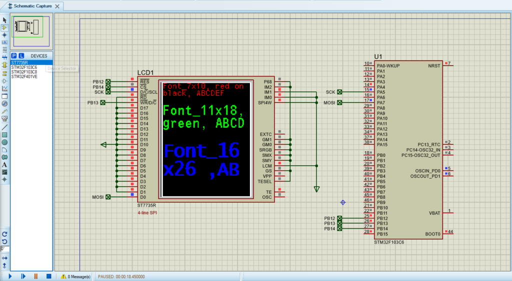
That’s all!
If you have any questions or suggestions don’t hesitate to leave a comment below.
4 comments
#include “testimg.h”
const uint16_t test_img_128x128[][128] = {
{0x0B6B,0x0B63,0x0B6B,0x2B6B,0x2B6B,0x2B6B………………………….};
What program was it converted with?
The image array test_img_128x128 was converted using the LCD Image Converter software. This tool allows you to convert images into arrays suitable for displaying on various LCDs and graphical displays. You can download and learn more about the software at the following link: LCD Image Converter.
Nice job! It’s an awesome library!
I’m planning to create some custom fonts for it, but every font creator I’ve used generates 1 byte of data (like 0x08). How can I make it compatible with your library?
Do you recommend any specific tools or applications for this purpose?
Thanks for your cooperation!
To create custom fonts compatible with the STM32 and ST7735 display library, you can utilize the Font Rasteriser tool developed by Fun Stack Labs. This tool is specifically designed for embedded projects and can generate font data in a format suitable for your library.
Steps to Create Compatible Fonts:
Access the Font Rasteriser Tool:
Navigate to the Font Rasteriser tool: https://funstacklabs.github.io/font-rasteriser.html
Design and Generate Font Data:
Select your desired font, size, and style within the tool.
The tool will generate the corresponding font data, typically in the form of C arrays, compatible with your STM32 library.
Integrate the Font Data into Your Project:
Copy the generated font data into your fonts.c file.
Ensure that the data structure matches the format expected by your library.
Declare the new font array as an external variable in your fonts.h file to make it accessible throughout your project.
By following these steps, you can create and integrate custom fonts tailored to your application’s requirements. The Font Rasteriser tool simplifies the process, ensuring compatibility with your existing STM32 and ST7735 display setup