In this article, we explore the Load Cell Amplifier HX711 and its integration with STM32 microcontrollers to achieve precise weight measurements.
Things used in this project
Software apps and online services:
1- STMicroelectronics STM32CubeMX
2- STMicroelectronics STM32CubeIDE
3- Proteus 8
Load Cell Amplifier HX711 with STM32 Microcontroller: A Comprehensive Guide
Accurate weight measurement is crucial in various applications, from industrial scales to kitchen devices. The SparkFun Load Cell Amplifier HX711, combined with an STM32 microcontroller, provides a robust solution for precise weight measurements. This article explores the integration of the HX711 with an STM32 microcontroller, offering a detailed guide on setup, calibration, and implementation.
Understanding Load Cells with STM32 Integration
- What is a Load Cell?
A load cell is a transducer that converts force into an electrical signal. This signal’s magnitude is directly proportional to the force applied. There are various types of load cells, including hydraulic, pneumatic, and strain gauge. - Strain Gauge Load Cells
Strain gauge load cells are the most commonly used in industrial applications. They offer high stiffness, excellent resonance values, and long life cycles. These load cells operate on the principle that a strain gauge deforms when the load cell material deforms. This deformation changes the strain gauge’s electrical resistance, proportional to the strain, which can be measured and calibrated to determine the applied load.
A typical strain gauge load cell consists of four strain gauges arranged in a Wheatstone bridge configuration. The output signal is usually in the millivolt range and requires amplification before it can be processed.High-resolution ADCs, such as the 24-bit ADC in the HX711, can directly read these signals.
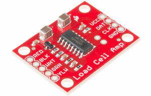
Overview of the HX711 Load Cell Amplifier for STM32 Projects
The HX711 is a precision 24-bit ADC designed for weigh scales and industrial control applications. It features:
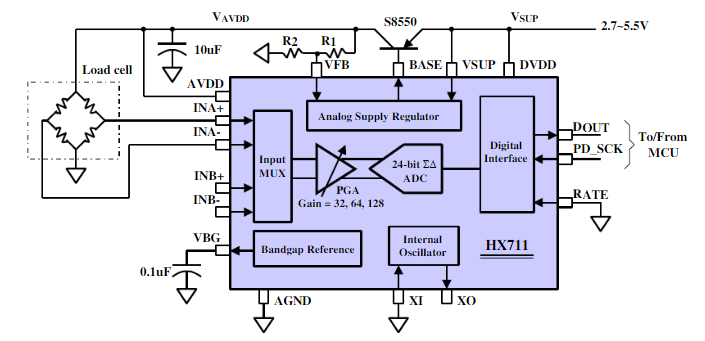
- Two selectable differential input channels
- On-chip active low noise PGA with selectable gain of 32, 64, and 128
- On-chip power supply regulator for the load cell and ADC analog power supply
- On-chip oscillator with optional external crystal
- On-chip power-on-reset
- Simple digital control and serial interface
- Selectable 10SPS or 80SPS output data rate
- Simultaneous 50 and 60Hz supply rejection
- Low current consumption: < 1.5mA during operation, < 1µA in power down mode
- Wide operating supply voltage range: 2.6V ~ 5.5V
- Operation temperature range: -40℃ ~ +85℃
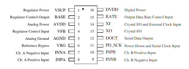
Pin Description of HX711 Load Cell Amplifier for STM32 Interfacing
Key Electrical Characteristics of the Load Cell Amplifier HX711
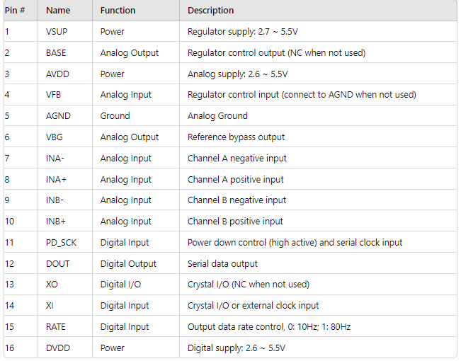
To initiate this project, we’ll configure GPIO pins PA1 (DT) and PA2 (SCK) for interfacing with the HX711 load cell, ensuring accurate weight measurement. We’ll then enable the TIM1 timer to create precise microsecond delays for the HX711 communication protocol, crucial for reliable data acquisition. Finally, we’ll integrate the HX711 into our system, using the STM32’s UART interface to transmit weight data to a serial monitor for real-time observation. This approach demonstrates effective utilization of the HX711 in embedded applications for precise weight detection.
STM32CubeMX Configuration:
- Open CubeMX & Create New Project Choose The Target MCU STM32F103C6 & Double-Click Its Name
- Go To The Clock Configuration & Set The System Clock To 8MHz
Configuration for the GPIO Mode:
- Configure The GPIO Pins PA1 as Output Pin
- Configure The GPIO Pins PA2 as Input Pin
Configuration for the TIMER Mode:
- In the Categories tab, select the TIM1
- Enable Internal Clock
- In the Parameter settings tab, set the (Prescaler=0 & Counter Peroid 65535)
Configuration for the UART Mode:
- Enable USART1 Module (Asynchronous Mode)
- Set the USART1 communication parameters (baud rate = 9600, parity=NON, stop bits =1, and word length = 8bits)
- Generate The Initialization Code & Open The Project In CubeIDE
STM32CubeIDE Configuration:
- Write The Application Layer Code
- hx711.h , hx711.c
- main.c
/* Includes ------------------------------------------------------------------*/
#include "main.h"

/* Private includes ----------------------------------------------------------*/
/* USER CODE BEGIN Includes */
#include "hx711.h"
#include <stdio.h>
#include <string.h>

/* Private variables ---------------------------------------------------------*/
TIM_HandleTypeDef htim1;

UART_HandleTypeDef huart1;

/* USER CODE BEGIN PV */
hx711_t loadcell;
float weight;
char MSG[50];
char MSG1[] = "HX711 scale demo \n\r";
char MSG2[] = "Reset scale to 0 assuming no weight at startup.\n\r";

/* Private function prototypes -----------------------------------------------*/
void SystemClock_Config(void);
static void MX_GPIO_Init(void);
static void MX_TIM1_Init(void);
static void MX_USART1_UART_Init(void);


int main(void)
{

  /* Reset of all peripherals, Initializes the Flash interface and the Systick. */
  HAL_Init();
  /* Configure the system clock */
  SystemClock_Config();
  /* Initialize all configured peripherals */
  MX_GPIO_Init();
  MX_TIM1_Init();
  MX_USART1_UART_Init();
  /* USER CODE BEGIN 2 */
  HAL_UART_Transmit(&huart1, (uint8_t*)MSG1, strlen(MSG1), 100);
  HAL_UART_Transmit(&huart1, (uint8_t*)MSG2, strlen(MSG2), 100);

  hx711_init(&loadcell, GPIOA, GPIO_PIN_1, GPIOA, GPIO_PIN_2);
  hx711_coef_set(&loadcell, 36057.14); // read afer calibration  36057.14
  hx711_tare(&loadcell, 10);
  /* USER CODE END 2 */

  /* USER CODE BEGIN WHILE */
  while (1)
  {
    /* USER CODE END WHILE */
    /* USER CODE BEGIN 3 */
    HAL_Delay(500);
    weight = hx711_weight(&loadcell, 10);
    HAL_Delay(10);
    sprintf(MSG,"\n\rhx711_weight = %.2f Kg\n\r",weight);
    HAL_UART_Transmit(&huart1,(uint8_t*)MSG, strlen(MSG), 100);
  }
  /* USER CODE END 3 */
}
#ifndef HX711_H_
#define HX711_H_

#include "main.h"

// HX711 configuration structure
typedef struct {
    GPIO_TypeDef *clk_gpio;  // GPIO port for the clock signal
    GPIO_TypeDef *dat_gpio;  // GPIO port for the data signal
    uint16_t clk_pin;        // GPIO pin for the clock signal
    uint16_t dat_pin;        // GPIO pin for the data signal
    int32_t offset;          // Offset value for tare
    float coef;              // Calibration coefficient
    uint8_t lock;            // Lock flag for synchronization
} hx711_t;

// Function prototypes
void hx711_delay_us(uint32_t us);
void hx711_init(hx711_t *hx711, GPIO_TypeDef *clk_gpio, uint16_t clk_pin, GPIO_TypeDef *dat_gpio, uint16_t dat_pin);
int32_t hx711_value(hx711_t *hx711);
int32_t hx711_value_ave(hx711_t *hx711, uint16_t sample);
void hx711_coef_set(hx711_t *hx711, float coef);
float hx711_coef_get(hx711_t *hx711);
void hx711_calibration(hx711_t *hx711, int32_t value_noload, int32_t value_load, float scale);
void hx711_tare(hx711_t *hx711, uint16_t sample);
float hx711_weight(hx711_t *hx711, uint16_t sample);
void hx711_power_down(hx711_t *hx711);
void hx711_power_up(hx711_t *hx711);

#endif
#include "hx711.h"

#define hx711_delay(x)    HAL_Delay(x)
extern TIM_HandleTypeDef htim1;

// Delay function using a timer for microsecond precision
void hx711_delay_us(uint32_t us) {
    uint32_t timer_ticks = (SystemCoreClock / 1000000) * us;
    __HAL_TIM_SET_COUNTER(&htim1, 0);
    HAL_TIM_Base_Start(&htim1);
    while (__HAL_TIM_GET_COUNTER(&htim1) < timer_ticks);
    HAL_TIM_Base_Stop(&htim1);
}

// Lock function to ensure mutual exclusion
void hx711_lock(hx711_t *hx711) {
    while (hx711->lock) {
        hx711_delay(1);
    }
    hx711->lock = 1;
}

// Unlock function to release mutual exclusion
void hx711_unlock(hx711_t *hx711) {
    hx711->lock = 0;
}

// Initialization function for HX711
void hx711_init(hx711_t *hx711, GPIO_TypeDef *clk_gpio, uint16_t clk_pin, GPIO_TypeDef *dat_gpio, uint16_t dat_pin) {
    hx711_lock(hx711);

    hx711->clk_gpio = clk_gpio;
    hx711->clk_pin = clk_pin;
    hx711->dat_gpio = dat_gpio;
    hx711->dat_pin = dat_pin;

    GPIO_InitTypeDef gpio = {0};
    gpio.Mode = GPIO_MODE_OUTPUT_PP;
    gpio.Pull = GPIO_NOPULL;
    gpio.Speed = GPIO_SPEED_FREQ_HIGH;
    gpio.Pin = clk_pin;
    HAL_GPIO_Init(clk_gpio, &gpio);

    gpio.Mode = GPIO_MODE_INPUT;
    gpio.Pull = GPIO_PULLUP;
    gpio.Pin = dat_pin;
    HAL_GPIO_Init(dat_gpio, &gpio);

    HAL_GPIO_WritePin(hx711->clk_gpio, hx711->clk_pin, GPIO_PIN_SET);
    hx711_delay(10);
    HAL_GPIO_WritePin(hx711->clk_gpio, hx711->clk_pin, GPIO_PIN_RESET);
    hx711_delay(10);

    hx711_value(hx711);
    hx711_value(hx711);

    hx711_unlock(hx711);
}

// Function to read a value from HX711
int32_t hx711_value(hx711_t *hx711) {
    uint32_t data = 0;
    uint32_t startTime = HAL_GetTick();

    while (HAL_GPIO_ReadPin(hx711->dat_gpio, hx711->dat_pin) == GPIO_PIN_SET) {
        hx711_delay(1);
        if (HAL_GetTick() - startTime > 150) {
            return 0;
        }
    }

    for (int8_t i = 0; i < 24; i++) {
        HAL_GPIO_WritePin(hx711->clk_gpio, hx711->clk_pin, GPIO_PIN_SET);
        hx711_delay_us(1);
        HAL_GPIO_WritePin(hx711->clk_gpio, hx711->clk_pin, GPIO_PIN_RESET);
        hx711_delay_us(1);
        data = data << 1;
        if (HAL_GPIO_ReadPin(hx711->dat_gpio, hx711->dat_pin) == GPIO_PIN_SET) {
            data++;
        }
    }

    data ^= 0x800000;
    HAL_GPIO_WritePin(hx711->clk_gpio, hx711->clk_pin, GPIO_PIN_SET);
    hx711_delay_us(1);
    HAL_GPIO_WritePin(hx711->clk_gpio, hx711->clk_pin, GPIO_PIN_RESET);
    hx711_delay_us(1);

    return data;
}

// Function to get an average value from HX711
int32_t hx711_value_ave(hx711_t *hx711, uint16_t sample) {
    hx711_lock(hx711);

    int64_t ave = 0;
    for (uint16_t i = 0; i < sample; i++) {
        ave += hx711_value(hx711);
        hx711_delay(5);
    }

    int32_t answer = (int32_t)(ave / sample);
    hx711_unlock(hx711);

    return answer;
}

// Function to tare the HX711 (set the offset)
void hx711_tare(hx711_t *hx711, uint16_t sample) {
    hx711_lock(hx711);

    int64_t ave = 0;
    for (uint16_t i = 0; i < sample; i++) {
        ave += hx711_value(hx711);
        hx711_delay(5);
    }

    hx711->offset = (int32_t)(ave / sample);
    hx711_unlock(hx711);
}

// Calibration function for HX711
void hx711_calibration(hx711_t *hx711, int32_t noload_raw, int32_t load_raw, float scale) {
    hx711_lock(hx711);

    hx711->offset = noload_raw;
    hx711->coef = (load_raw - noload_raw) / scale;

    hx711_unlock(hx711);
}

// Function to get weight using HX711
float hx711_weight(hx711_t *hx711, uint16_t sample) {
    hx711_lock(hx711);

    int64_t ave = 0;
    for (uint16_t i = 0; i < sample; i++) {
        ave += hx711_value(hx711);
        hx711_delay(5);
    }

    int32_t data = (int32_t)(ave / sample);
    float answer = (data - hx711->offset) / hx711->coef;
    hx711_unlock(hx711);

    return answer;
}

// Function to set the calibration coefficient
void hx711_coef_set(hx711_t *hx711, float coef) {
    hx711->coef = coef;
}

// Function to get the calibration coefficient
float hx711_coef_get(hx711_t *hx711) {
    return hx711->coef;
}

// Function to power down HX711
void hx711_power_down(hx711_t *hx711) {
    HAL_GPIO_WritePin(hx711->clk_gpio, hx711->clk_pin, GPIO_PIN_RESET);
    HAL_GPIO_WritePin(hx711->clk_gpio, hx711->clk_pin, GPIO_PIN_SET);
    hx711_delay(1);
}

// Function to power up HX711
void hx711_power_up(hx711_t *hx711) {
    HAL_GPIO_WritePin(hx711->clk_gpio, hx711->clk_pin, GPIO_PIN_RESET);
}
Proteus Configuration :
- Open Proteus & Create New Project and click next

- Click on Virtual Instruments Mode then choose DC VOLTMETER
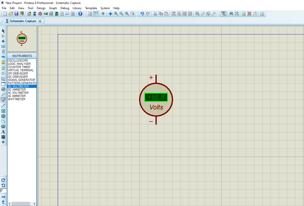
- Click on Pick Device
- Search for STM32F103C6 & RES & CAPACITOR & HX711 & CAP-ELEC & LOADCELL & EN4403
- Click on Terminal Mode then choose (DYNAMIC&POWER &GROUND)
- finally make the circuit below and start the simulation
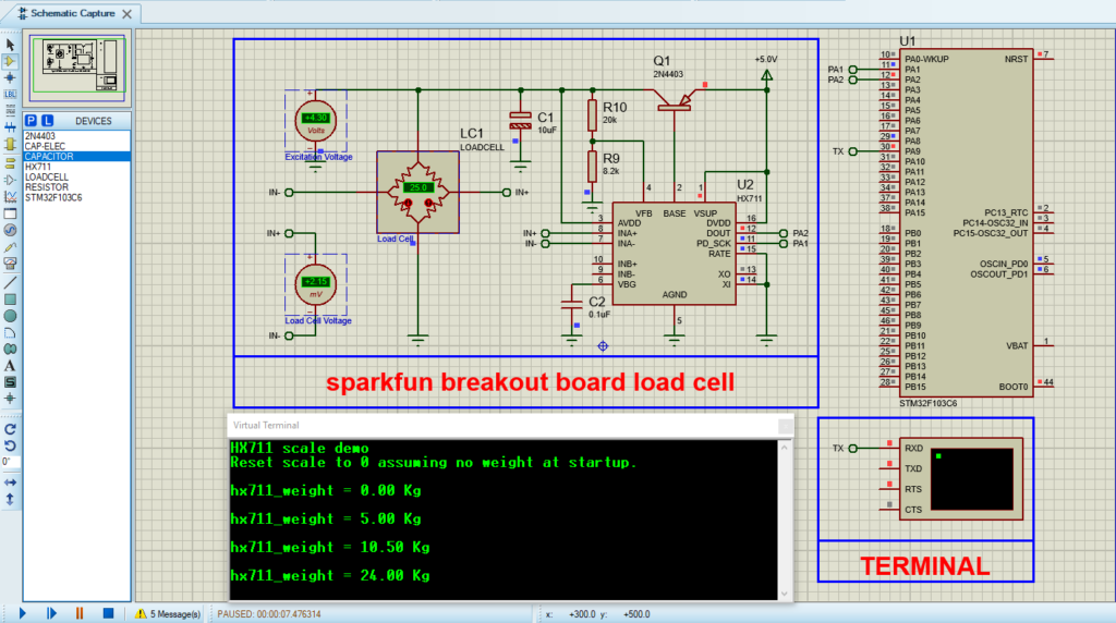
That’s all!
If you have any questions or suggestions don’t hesitate to leave a comment below
