
In this article, we will explore interfacing multiple displays through MAX7219 using STM32. We will cover the necessary hardware components, circuit design, and software implementation, providing a comprehensive guide for your STM32 projects.

Things used in this project
Software apps and online services:
1- STMicroelectronics STM32CubeMX
2- STMicroelectronics STM32CubeIDE
3- Proteus 8
Simplified Display Integration: Matrix LED and 7-Segment Displays with STM32 via MAX7219 and SPI:
This project aims to teach you about the Serial Peripheral Interface (SPI) and how to interface Matrix LED 8×8 and 7-Segment Displays with an STM32 microcontroller using MAX7219 as the display driver. The article focuses on implementing the displays through the SPI communication protocol and simulating the project in Proteus software.
MAX7219:
MAX7219 is a popular display driver IC that simplifies the process of interfacing multiple displays with a microcontroller. It is designed to drive up to 64 individual LED segments or 8 digits of 7-segment displays. The IC handles the multiplexing and driving of the displays and uses SPI communication protocol to interface with the microcontroller.
Matrix LED Display:
A matrix LED display is a type of display that consists of a grid of LEDs arranged in rows and columns. Each LED can be individually controlled to display a specific pattern, character or symbol. Matrix LED displays are commonly used in digital signage, scoreboards, and outdoor displays due to their high brightness and visibility.
7-Segment Display:
A 7-segment display is a type of electronic display device that can display numbers and some letters using seven segments. Each segment can be controlled individually to display a specific number or letter. 7-segment displays are widely used in digital clocks, calculators, and other electronic devices where numeric output is required.
In this project, we will walk you through the process of interfacing the Matrix LED and 7-Segment Displays with the STM32 microcontroller using MAX7219 as the display driver and SPI communication protocol. We will also demonstrate how to simulate the project in Proteus software to verify the functionality of the system
STM32CubeMX Configuration:
- Open CubeMX & Create New Project Choose The Target MCU STM32F103C6 & Double-Click Its Name
- Go To The Clock Configuration & Set The System Clock To 8MHz
- Configure The GPIO Pin PB0 as Output Pin
7 Segment Configuration:
- Configure The GPIO Pin PA4 as Output Pin (CSPin)
- In the Categories tab, select the SPI1 & Transmit Only Master
Matrix LED Configuration:
- Configure The GPIO Pin PB12 as Output Pin (CSPin)
- In the Categories tab, select the SPI2 & Transmit Only Master
- Generate The Initialization Code & Open The Project In CubeIDE
STM32CubeIDE Configuration :
- Write The Application Layer Code
- MAX7219.h & MAX7219.c
- main.c
/*
 * MAX7219.h
*/

#ifndef MAX7219_H_
#define MAX7219_H_

#include "main.h"
#include "stdbool.h"

#define NUMBER_OF_DIGITS  8
#define SPI_PORT      hspi1

extern SPI_HandleTypeDef  SPI_PORT;

typedef enum {
  REG_NO_OP       = 0x00,
  REG_DIGIT_0     = 0x01,
  REG_DIGIT_1     = 0x02,
  REG_DIGIT_2     = 0x03,
  REG_DIGIT_3     = 0x04,
  REG_DIGIT_4     = 0x05,
  REG_DIGIT_5     = 0x06,
  REG_DIGIT_6     = 0x07,
  REG_DIGIT_7     = 0x08,
  REG_DECODE_MODE   = 0x09,
  REG_INTENSITY     = 0x0A,
  REG_SCAN_LIMIT    = 0x0B,
  REG_SHUTDOWN    = 0x0C,
  REG_DISPLAY_TEST  = 0x0F,
} MAX7219_REGISTERS;

typedef enum {
  DIGIT_1 = 1, DIGIT_2 = 2, DIGIT_3 = 3, DIGIT_4 = 4,
  DIGIT_5 = 5, DIGIT_6 = 6, DIGIT_7 = 7, DIGIT_8 = 8
} MAX7219_Digits;

typedef enum {
  NUM_0   = 0x00,
  NUM_1   = 0x01,
  NUM_2   = 0x02,
  NUM_3   = 0x03,
  NUM_4   = 0x04,
  NUM_5   = 0x05,
  NUM_6   = 0x06,
  NUM_7   = 0x07,
  NUM_8   = 0x08,
  NUM_9   = 0x09,
  MINUS   = 0x0A,
  BLANK   = 0x0F
}MAX7219_Numeric;

void max7219_Init_16SEG(uint8_t intensivity);
void max7219_SetIntensivity(uint8_t intensivity);
void max7219_Clean(void);
void max7219_SendData(uint8_t addr, uint8_t data);
void max7219_Turn_On(void);
void max7219_Turn_Off(void);
void max7219_Decode_On(void);
void max7219_Decode_Off(void);
void max7219_PrintDigit(MAX7219_Digits position, MAX7219_Numeric numeric, bool point);
MAX7219_Digits max7219_PrintItos(MAX7219_Digits position, int value);
MAX7219_Digits max7219_PrintNtos(MAX7219_Digits position, uint32_t value, uint8_t n);
MAX7219_Digits max7219_PrintFtos(MAX7219_Digits position, float value, uint8_t n);

#endif /* MAX7219_H_ *
/*
 * MAX7219.c
 */


#include "max7219.h"

#define CS_SET() HAL_GPIO_WritePin(GPIOA,GPIO_PIN_4,GPIO_PIN_RESET)
#define CS_RESET() HAL_GPIO_WritePin(GPIOA,GPIO_PIN_4,GPIO_PIN_SET)

static uint8_t decodeMode = 0x00;

static uint8_t SYMBOLS[] = {
    0x7E, // numeric 0
    0x30, // numeric 1
    0x6D, // numeric 2
    0x79, // numeric 3
    0x33, // numeric 4
    0x5B, // numeric 5
    0x5F, // numeric 6
    0x70, // numeric 7
    0x7F, // numeric 8
    0x7B, // numeric 9
    0x01, // minus
    0x00  // blank
};

static uint16_t getSymbol(uint8_t number);
static uint32_t lcdPow10(uint8_t n);

void max7219_Init_16SEG(uint8_t intensivity)
{
  max7219_Turn_On();
  max7219_SendData(REG_SCAN_LIMIT, NUMBER_OF_DIGITS - 1);
  max7219_SetIntensivity(intensivity);
  max7219_Clean();
}

void max7219_SetIntensivity(uint8_t intensivity)
{
  if (intensivity > 0x0F)
  {
    return;
  }

  max7219_SendData(REG_INTENSITY, intensivity);
}

void max7219_Clean()
{
  uint8_t clear = 0x00;

  if(decodeMode == 0xFF)
  {
    clear = BLANK;
  }

  for (int i = 0; i < 8; ++i)
  {
    max7219_SendData(i + 1, clear);
  }
}

void max7219_SendData(uint8_t addr, uint8_t data)
{
  CS_SET();
  HAL_SPI_Transmit(&hspi1, &addr, 1, HAL_MAX_DELAY);
  HAL_SPI_Transmit(&hspi1, &data, 1, HAL_MAX_DELAY);
  CS_RESET();
}

void max7219_Turn_On(void)
{
  max7219_SendData(REG_SHUTDOWN, 0x01);
}

void max7219_Turn_Off(void)
{
  max7219_SendData(REG_SHUTDOWN, 0x00);
}

void max7219_Decode_On(void)
{
  decodeMode = 0xFF;
  max7219_SendData(REG_DECODE_MODE, decodeMode);
}

void max7219_Decode_Off(void)
{
  decodeMode = 0x00;
  max7219_SendData(REG_DECODE_MODE, decodeMode);
}

void max7219_PrintDigit(MAX7219_Digits position, MAX7219_Numeric numeric, bool point)
{
  if(position > NUMBER_OF_DIGITS)
  {
    return;
  }

  if(point)
  {
    if(decodeMode == 0x00)
    {
      max7219_SendData(position, getSymbol(numeric) | (1 << 7));
    }
    else if(decodeMode == 0xFF)
    {
      max7219_SendData(position, numeric | (1 << 7));
    }
  }
  else
  {
    if(decodeMode == 0x00)
    {
      max7219_SendData(position, getSymbol(numeric) & (~(1 << 7)));
    }
    else if(decodeMode == 0xFF)
    {
      max7219_SendData(position, numeric & (~(1 << 7)));
    }
  }
}

MAX7219_Digits max7219_PrintItos(MAX7219_Digits position, int value)
{
  max7219_SendData(REG_DECODE_MODE, 0xFF);

  int32_t i;

  if (value < 0)
  {
    if(position > 0)
    {
      max7219_SendData(position, MINUS);
      position--;
    }
    value = -value;
  }

  i = 1;

  while ((value / i) > 9)
  {
    i *= 10;
  }

  if(position > 0)
  {
    max7219_SendData(position, value/i);
    position--;
  }

  i /= 10;

  while (i > 0)
  {
    if(position > 0)
    {
      max7219_SendData(position, (value % (i * 10)) / i);
      position--;
    }

    i /= 10;
  }

  max7219_SendData(REG_DECODE_MODE, decodeMode);

  return position;
}

MAX7219_Digits max7219_PrintNtos(MAX7219_Digits position, uint32_t value, uint8_t n)
{
  max7219_SendData(REG_DECODE_MODE, 0xFF);

  if (n > 0u)
  {
    uint32_t i = lcdPow10(n - 1u);

    while (i > 0u)  /* Display at least one symbol */
    {
      if(position > 0u)
      {
        max7219_SendData(position, (value / i) % 10u);
        position--;
      }

      i /= 10u;
    }
  }

  max7219_SendData(REG_DECODE_MODE, decodeMode);

  return position;
}

MAX7219_Digits max7219_PrintFtos(MAX7219_Digits position, float value, uint8_t n)
{
  if(n > 4)
  {
    n = 4;
  }

  max7219_SendData(REG_DECODE_MODE, 0xFF);

  if (value < 0.0)
  {
    if(position > 0)
    {
      max7219_SendData(position, MINUS);
      position--;
    }

    value = -value;
  }

  position = max7219_PrintItos(position, (int32_t) value);

  if (n > 0u)
  {
    max7219_PrintDigit(position + 1, ((int32_t) value) % 10, true);

    position = max7219_PrintNtos(position, (uint32_t) (value * (float) lcdPow10(n)), n);
  }

  max7219_SendData(REG_DECODE_MODE, decodeMode);

  return position;
}

static uint16_t getSymbol(uint8_t number)
{
  return SYMBOLS[number];
}

static uint32_t lcdPow10(uint8_t n)
{
  uint32_t retval = 1u;

  while (n > 0u)
  {
    retval *= 10u;
    n--;
  }

  return retval;
}
#include "main.h"
#include "max7219.h"

uint8_t disp1ay[38][8]={
{0x3C,0x42,0x42,0x42,0x42,0x42,0x42,0x3C},  //0
{0x10,0x30,0x50,0x10,0x10,0x10,0x10,0x7c},  //1
{0x7E,0x2,0x2,0x7E,0x40,0x40,0x40,0x7E},    //2
{0x3E,0x2,0x2,0x3E,0x2,0x2,0x3E,0x0},       //3
{0x8,0x18,0x28,0x48,0xFE,0x8,0x8,0x8},      //4
{0x3C,0x20,0x20,0x3C,0x4,0x4,0x3C,0x0},     //5
{0x3C,0x20,0x20,0x3C,0x24,0x24,0x3C,0x0},   //6
{0x3E,0x22,0x4,0x8,0x8,0x8,0x8,0x8},        //7
{0x0,0x3E,0x22,0x22,0x3E,0x22,0x22,0x3E},   //8
{0x3E,0x22,0x22,0x3E,0x2,0x2,0x2,0x3E},     //9
{0x18,0x24,0x42,0x42,0x7E,0x42,0x42,0x42},  //A
{0x3C,0x22,0x22,0x3c,0x22,0x22,0x3C,0x0},   //B
{0x3C,0x40,0x40,0x40,0x40,0x40,0x40,0x3C},  //C
{0x7C,0x22,0x22,0x22,0x22,0x22,0x22,0x7C},  //D
{0x7C,0x40,0x40,0x7C,0x40,0x40,0x40,0x7C},  //E
{0x7C,0x40,0x40,0x7C,0x40,0x40,0x40,0x40},  //F
{0x3C,0x40,0x40,0x40,0x4c,0x44,0x44,0x3C},  //G
{0x44,0x44,0x44,0x7C,0x44,0x44,0x44,0x44},  //H
{0x7C,0x10,0x10,0x10,0x10,0x10,0x10,0x7C},  //I
{0x3C,0x8,0x8,0x8,0x8,0x8,0x48,0x30},       //J
{0x0,0x24,0x28,0x30,0x20,0x30,0x28,0x24},   //K
{0x40,0x40,0x40,0x40,0x40,0x40,0x40,0x7C},  //L
{0x81,0xC3,0xA5,0x99,0x81,0x81,0x81,0x81},  //M
{0x0,0x42,0x62,0x52,0x4A,0x46,0x42,0x0},    //N
{0x3C,0x42,0x42,0x42,0x42,0x42,0x42,0x3C},  //O
{0x3C,0x22,0x22,0x22,0x3C,0x20,0x20,0x20},  //P
{0x1C,0x22,0x22,0x22,0x22,0x26,0x22,0x1D},  //Q
{0x3C,0x22,0x22,0x22,0x3C,0x24,0x22,0x21},  //R
{0x0,0x1E,0x20,0x20,0x3E,0x2,0x2,0x3C},     //S
{0x0,0x3E,0x8,0x8,0x8,0x8,0x8,0x8},         //T
{0x42,0x42,0x42,0x42,0x42,0x42,0x22,0x1C},  //U
{0x42,0x42,0x42,0x42,0x42,0x42,0x24,0x18},  //V
{0x0,0x49,0x49,0x49,0x49,0x2A,0x1C,0x0},    //W
{0x0,0x41,0x22,0x14,0x8,0x14,0x22,0x41},    //X
{0x41,0x22,0x14,0x8,0x8,0x8,0x8,0x8},       //Y
{0x0,0x7F,0x2,0x4,0x8,0x10,0x20,0x7F},      //Z
};

static void write_reg(uint8_t reg, uint8_t value)
{
  uint8_t tx_data[2] = {reg, value };
  HAL_GPIO_WritePin(GPIOB, GPIO_PIN_12, GPIO_PIN_RESET);
  HAL_SPI_Transmit(&hspi2, tx_data, sizeof(tx_data),100);
  HAL_GPIO_WritePin(GPIOB, GPIO_PIN_12, GPIO_PIN_SET);
}

static void max7219_init_8x8MAT() {
  write_reg(0x09, 0x00);       //  no decoding
  write_reg(0x0a, 0x03);       //  brightness intensity
  write_reg(0x0b, 0x07);       //  scan limit = 8 LEDs
  write_reg(0x0c, 0x01);       //  power down =0,normal mode = 1
  write_reg(0x0f, 0x00);       //  no test display

}


int main(void)
{
  HAL_Init()
  SystemClock_Config();
  MX_GPIO_Init();
  MX_SPI1_Init();
  MX_SPI2_Init();

  /* USER CODE BEGIN 2 */
  max7219_init_8x8MAT();
  HAL_Delay(10);
  max7219_Init_16SEG(7);
  max7219_Decode_On();
  /* USER CODE END 2 */

  while (1)
  {
    switch(HAL_GPIO_ReadPin(GPIOB, GPIO_PIN_0))
    {
        case(GPIO_PIN_SET):
          {
           max7219_PrintItos(DIGIT_8,87654321);
           HAL_Delay(2000);
           max7219_Clean();

           max7219_PrintFtos(DIGIT_8,-3.66,2);
           HAL_Delay(2000);
           max7219_Clean();

           max7219_PrintNtos(DIGIT_8,9999,4);
           HAL_Delay(2000);
           max7219_Clean();

           max7219_PrintNtos(DIGIT_8,9999,8);
           HAL_Delay(2000);
           max7219_Clean();
          }break;
        case(GPIO_PIN_RESET):
           {
              for(int j=0 ; j<38;j++)
              {
                for(int i=1;i<9;i++)
                {
                  write_reg(i,  disp1ay[j][i-1]);
                }
                HAL_Delay(700);
              }
           }break;
}}}
Proteus Configuration :
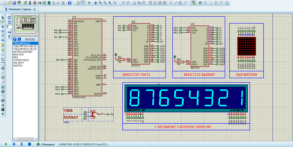
- Open Proteus & Create New Project and click next

- Click on Pick Device
- Search for STM32F103C8 & MAX7219 & MATRIX 8×8 RED & 7SEG_MPX8_CC_BLUE, RES
- Click on Terminal Mode then choose (DEFAULT & POWER &GROUND)
- finally make the circuit below and start the simulation
That’s all!
If you have any questions or suggestions don’t hesitate to leave a comment below.