
In this article, we’ll cover how to interface the SSD1306 OLED with STM32 using SPI communication, providing a step-by-step guide to set up the display and configure SPI on your STM32 microcontroller.
Things used in this project
Software apps and online services
1- STMicroelectronics STM32CubeMX
2- STMicroelectronics STM32CubeIDE
3- Proteus 8
Exploring STM32 Microcontroller Integration with SSD1306 OLED Display
In this project, the focus is on interfacing the SSD1306 OLED display with an STM32 microcontroller using the SPI communication protocol. Specifically, the project will cover initializing the SSD1306 OLED display, setting up the SPI interface on the STM32, and demonstrating basic display functions such as writing text and drawing shapes. Through this project, you will gain a comprehensive understanding of SPI communication and how to utilize it to control an OLED display with an STM32 microcontroller
Understanding SSD1306 OLED Display Capabilities Mode Implementation :
SSD1306 is commonly used in monochromatic OLED displays up to 128×64 screen resolution, offering a compact and efficient solution for portable and wearable devices. These displays emerge as the best alternative to conventional character LCDs, providing ease of interface via I2C or SPI. SSD1306 OLED displays excel in displaying complex graphics, including text, bitmap images, and animations.
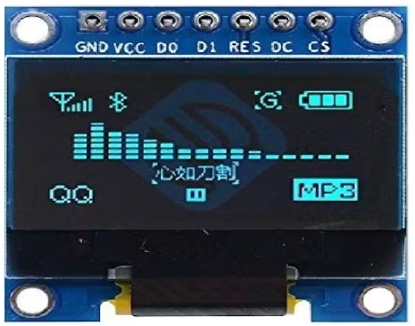
Comparing prices, small OLED displays prove to be a cost-effective choice compared to character LCDs. Moreover, they offer aesthetic appeal and compactness, making them perfect for wearable and portable consumer devices such as smartwatches. While character LCDs fall short in such applications, and graphic LCDs prove costlier, small OLED displays perfectly cater to the needs of modern wearable technology.
Configuring STM32 SPI Peripheral for Communication:
To kick off our project, we’ll begin by configuring the STM32 microcontroller’s SPI peripheral as a Transmit-only Master. This step is crucial for establishing communication between the microcontroller and the SSD1306 display.
STM32CubeMX Configuration:
- Open CubeMX & Create New Project Choose The Target MCU STM32F103C6 & Double-Click Its Name
- Go To The Clock Configuration & Set The System Clock To 8MHz
Configuration for the SPI Mode:
- In the Categories tab, select the SPI1 & Transmit Only Master
- In the clock parameters, set the prescaler to 8 to achieve a baud rate of 4.0 Mbits/s.
Configuration for the GPIO:
- Configure The GPIO Pin PA3(DC) as Output Pin
- Configure The GPIO Pin PA4 (CS) as Output Pin
- Generate The Initialization Code & Open The Project In CubeIDE
STM32CubeIDE Configuration:
- Write The Application Layer Code
- oled.h & oled.c
- fonts.h & fonts.c
/*
 * fonts.h
 *
 *  Created on: Apr 9, 2024
 *      Author: PC-MAGHREBI
 */

#ifndef INC_FONTS_H_
#define INC_FONTS_H_

/* C++ detection */
#ifdef __cplusplus
extern C {
#endif

/**
 *
 * Default fonts library. It is used in all LCD based libraries.
 *
 * \par Supported fonts
 *
 * Currently, these fonts are supported:
 *  - 7 x 10 pixels
 *  - 11 x 18 pixels
 *  - 16 x 26 pixels
 */
//#include "stm32f7xx.h"                  // Device header

#include "stdint.h"
#include "string.h"

/**
 * @defgroup LIB_Typedefs
 * @brief    Library Typedefs
 * @{
 */

/**
 * @brief  Font structure used on my LCD libraries
 */
typedef struct {
  uint8_t FontWidth;    /*!< Font width in pixels */
  uint8_t FontHeight;   /*!< Font height in pixels */
  const uint16_t *data; /*!< Pointer to data font data array */
} FontDef_t;

/**
 * @brief  String length and height
 */
typedef struct {
  uint16_t Length;      /*!< String length in units of pixels */
  uint16_t Height;      /*!< String height in units of pixels */
} FONTS_SIZE_t;

/**
 * @}
 */

/**
 * @defgroup FONTS_FontVariables
 * @brief    Library font variables
 * @{
 */

/**
 * @brief  7 x 10 pixels font size structure
 */
extern FontDef_t Font_7x10;

/**
 * @brief  11 x 18 pixels font size structure
 */
extern FontDef_t Font_11x18;

/**
 * @brief  16 x 26 pixels font size structure
 */
extern FontDef_t Font_16x26;

/**
 * @}
 */

/**
 * @defgroup FONTS_Functions
 * @brief    Library functions
 * @{
 */

/**
 * @brief  Calculates string length and height in units of pixels depending on string and font used
 * @param  *str: String to be checked for length and height
 * @param  *SizeStruct: Pointer to empty @ref FONTS_SIZE_t structure where informations will be saved
 * @param  *Font: Pointer to @ref FontDef_t font used for calculations
 * @retval Pointer to string used for length and height
 */
char* FONTS_GetStringSize(char* str, FONTS_SIZE_t* SizeStruct, FontDef_t* Font);

/**
 * @}
 */

/**
 * @}
 */

/**
 * @}
 */

/* C++ detection */
#ifdef __cplusplus
}
#endif

#endif /* INC_FONTS_H_ */
/*
 * fonts.c
 *
 *  Created on: Apr 9, 2024
 *      Author: PC-MAGHREBI
 */


#include "fonts.h"

const uint16_t Font7x10 [] = {
0x0000, 0x0000, 0x0000, 0x0000, 0x0000, 0x0000, 0x0000, 0x0000, 0x0000, 0x0000,  // sp
0x1000, 0x1000, 0x1000, 0x1000, 0x1000, 0x1000, 0x0000, 0x1000, 0x0000, 0x0000,  // !
0x2800, 0x2800, 0x2800, 0x0000, 0x0000, 0x0000, 0x0000, 0x0000, 0x0000, 0x0000,  // "
0x2400, 0x2400, 0x7C00, 0x2400, 0x4800, 0x7C00, 0x4800, 0x4800, 0x0000, 0x0000,  // #
0x3800, 0x5400, 0x5000, 0x3800, 0x1400, 0x5400, 0x5400, 0x3800, 0x1000, 0x0000,  // $
0x2000, 0x5400, 0x5800, 0x3000, 0x2800, 0x5400, 0x1400, 0x0800, 0x0000, 0x0000,  // %
0x1000, 0x2800, 0x2800, 0x1000, 0x3400, 0x4800, 0x4800, 0x3400, 0x0000, 0x0000,  // &
0x1000, 0x1000, 0x1000, 0x0000, 0x0000, 0x0000, 0x0000, 0x0000, 0x0000, 0x0000,  // '
0x0800, 0x1000, 0x2000, 0x2000, 0x2000, 0x2000, 0x2000, 0x2000, 0x1000, 0x0800,  // (
0x2000, 0x1000, 0x0800, 0x0800, 0x0800, 0x0800, 0x0800, 0x0800, 0x1000, 0x2000,  // )
0x1000, 0x3800, 0x1000, 0x2800, 0x0000, 0x0000, 0x0000, 0x0000, 0x0000, 0x0000,  // *
0x0000, 0x0000, 0x1000, 0x1000, 0x7C00, 0x1000, 0x1000, 0x0000, 0x0000, 0x0000,  // +
0x0000, 0x0000, 0x0000, 0x0000, 0x0000, 0x0000, 0x0000, 0x1000, 0x1000, 0x1000,  // ,
0x0000, 0x0000, 0x0000, 0x0000, 0x0000, 0x3800, 0x0000, 0x0000, 0x0000, 0x0000,  // -
0x0000, 0x0000, 0x0000, 0x0000, 0x0000, 0x0000, 0x0000, 0x1000, 0x0000, 0x0000,  // .
0x0800, 0x0800, 0x1000, 0x1000, 0x1000, 0x1000, 0x2000, 0x2000, 0x0000, 0x0000,  // /
0x3800, 0x4400, 0x4400, 0x5400, 0x4400, 0x4400, 0x4400, 0x3800, 0x0000, 0x0000,  // 0
0x1000, 0x3000, 0x5000, 0x1000, 0x1000, 0x1000, 0x1000, 0x1000, 0x0000, 0x0000,  // 1
0x3800, 0x4400, 0x4400, 0x0400, 0x0800, 0x1000, 0x2000, 0x7C00, 0x0000, 0x0000,  // 2
0x3800, 0x4400, 0x0400, 0x1800, 0x0400, 0x0400, 0x4400, 0x3800, 0x0000, 0x0000,  // 3
0x0800, 0x1800, 0x2800, 0x2800, 0x4800, 0x7C00, 0x0800, 0x0800, 0x0000, 0x0000,  // 4
0x7C00, 0x4000, 0x4000, 0x7800, 0x0400, 0x0400, 0x4400, 0x3800, 0x0000, 0x0000,  // 5
0x3800, 0x4400, 0x4000, 0x7800, 0x4400, 0x4400, 0x4400, 0x3800, 0x0000, 0x0000,  // 6
0x7C00, 0x0400, 0x0800, 0x1000, 0x1000, 0x2000, 0x2000, 0x2000, 0x0000, 0x0000,  // 7
0x3800, 0x4400, 0x4400, 0x3800, 0x4400, 0x4400, 0x4400, 0x3800, 0x0000, 0x0000,  // 8
0x3800, 0x4400, 0x4400, 0x4400, 0x3C00, 0x0400, 0x4400, 0x3800, 0x0000, 0x0000,  // 9
0x0000, 0x0000, 0x1000, 0x0000, 0x0000, 0x0000, 0x0000, 0x1000, 0x0000, 0x0000,  // :
0x0000, 0x0000, 0x0000, 0x1000, 0x0000, 0x0000, 0x0000, 0x1000, 0x1000, 0x1000,  // ;
0x0000, 0x0000, 0x0C00, 0x3000, 0x4000, 0x3000, 0x0C00, 0x0000, 0x0000, 0x0000,  // <
0x0000, 0x0000, 0x0000, 0x7C00, 0x0000, 0x7C00, 0x0000, 0x0000, 0x0000, 0x0000,  // =
0x0000, 0x0000, 0x6000, 0x1800, 0x0400, 0x1800, 0x6000, 0x0000, 0x0000, 0x0000,  // >
0x3800, 0x4400, 0x0400, 0x0800, 0x1000, 0x1000, 0x0000, 0x1000, 0x0000, 0x0000,  // ?
0x3800, 0x4400, 0x4C00, 0x5400, 0x5C00, 0x4000, 0x4000, 0x3800, 0x0000, 0x0000,  // @
0x1000, 0x2800, 0x2800, 0x2800, 0x2800, 0x7C00, 0x4400, 0x4400, 0x0000, 0x0000,  // A
0x7800, 0x4400, 0x4400, 0x7800, 0x4400, 0x4400, 0x4400, 0x7800, 0x0000, 0x0000,  // B
0x3800, 0x4400, 0x4000, 0x4000, 0x4000, 0x4000, 0x4400, 0x3800, 0x0000, 0x0000,  // C
0x7000, 0x4800, 0x4400, 0x4400, 0x4400, 0x4400, 0x4800, 0x7000, 0x0000, 0x0000,  // D
0x7C00, 0x4000, 0x4000, 0x7C00, 0x4000, 0x4000, 0x4000, 0x7C00, 0x0000, 0x0000,  // E
0x7C00, 0x4000, 0x4000, 0x7800, 0x4000, 0x4000, 0x4000, 0x4000, 0x0000, 0x0000,  // F
0x3800, 0x4400, 0x4000, 0x4000, 0x5C00, 0x4400, 0x4400, 0x3800, 0x0000, 0x0000,  // G
0x4400, 0x4400, 0x4400, 0x7C00, 0x4400, 0x4400, 0x4400, 0x4400, 0x0000, 0x0000,  // H
0x3800, 0x1000, 0x1000, 0x1000, 0x1000, 0x1000, 0x1000, 0x3800, 0x0000, 0x0000,  // I
0x0400, 0x0400, 0x0400, 0x0400, 0x0400, 0x0400, 0x4400, 0x3800, 0x0000, 0x0000,  // J
0x4400, 0x4800, 0x5000, 0x6000, 0x5000, 0x4800, 0x4800, 0x4400, 0x0000, 0x0000,  // K
0x4000, 0x4000, 0x4000, 0x4000, 0x4000, 0x4000, 0x4000, 0x7C00, 0x0000, 0x0000,  // L
0x4400, 0x6C00, 0x6C00, 0x5400, 0x4400, 0x4400, 0x4400, 0x4400, 0x0000, 0x0000,  // M
0x4400, 0x6400, 0x6400, 0x5400, 0x5400, 0x4C00, 0x4C00, 0x4400, 0x0000, 0x0000,  // N
0x3800, 0x4400, 0x4400, 0x4400, 0x4400, 0x4400, 0x4400, 0x3800, 0x0000, 0x0000,  // O
0x7800, 0x4400, 0x4400, 0x4400, 0x7800, 0x4000, 0x4000, 0x4000, 0x0000, 0x0000,  // P
0x3800, 0x4400, 0x4400, 0x4400, 0x4400, 0x4400, 0x5400, 0x3800, 0x0400, 0x0000,  // Q
0x7800, 0x4400, 0x4400, 0x4400, 0x7800, 0x4800, 0x4800, 0x4400, 0x0000, 0x0000,  // R
0x3800, 0x4400, 0x4000, 0x3000, 0x0800, 0x0400, 0x4400, 0x3800, 0x0000, 0x0000,  // S
0x7C00, 0x1000, 0x1000, 0x1000, 0x1000, 0x1000, 0x1000, 0x1000, 0x0000, 0x0000,  // T
0x4400, 0x4400, 0x4400, 0x4400, 0x4400, 0x4400, 0x4400, 0x3800, 0x0000, 0x0000,  // U
0x4400, 0x4400, 0x4400, 0x2800, 0x2800, 0x2800, 0x1000, 0x1000, 0x0000, 0x0000,  // V
0x4400, 0x4400, 0x5400, 0x5400, 0x5400, 0x6C00, 0x2800, 0x2800, 0x0000, 0x0000,  // W
0x4400, 0x2800, 0x2800, 0x1000, 0x1000, 0x2800, 0x2800, 0x4400, 0x0000, 0x0000,  // X
0x4400, 0x4400, 0x2800, 0x2800, 0x1000, 0x1000, 0x1000, 0x1000, 0x0000, 0x0000,  // Y
0x7C00, 0x0400, 0x0800, 0x1000, 0x1000, 0x2000, 0x4000, 0x7C00, 0x0000, 0x0000,  // Z
0x1800, 0x1000, 0x1000, 0x1000, 0x1000, 0x1000, 0x1000, 0x1000, 0x1000, 0x1800,  // [
0x2000, 0x2000, 0x1000, 0x1000, 0x1000, 0x1000, 0x0800, 0x0800, 0x0000, 0x0000,  /* \ */
0x3000, 0x1000, 0x1000, 0x1000, 0x1000, 0x1000, 0x1000, 0x1000, 0x1000, 0x3000,  // ]
0x1000, 0x2800, 0x2800, 0x4400, 0x0000, 0x0000, 0x0000, 0x0000, 0x0000, 0x0000,  // ^
0x0000, 0x0000, 0x0000, 0x0000, 0x0000, 0x0000, 0x0000, 0x0000, 0x0000, 0xFE00,  // _
0x2000, 0x1000, 0x0000, 0x0000, 0x0000, 0x0000, 0x0000, 0x0000, 0x0000, 0x0000,  // <code>
0x0000, 0x0000, 0x3800, 0x4400, 0x3C00, 0x4400, 0x4C00, 0x3400, 0x0000, 0x0000,  // a
0x4000, 0x4000, 0x5800, 0x6400, 0x4400, 0x4400, 0x6400, 0x5800, 0x0000, 0x0000,  // b
0x0000, 0x0000, 0x3800, 0x4400, 0x4000, 0x4000, 0x4400, 0x3800, 0x0000, 0x0000,  // c
0x0400, 0x0400, 0x3400, 0x4C00, 0x4400, 0x4400, 0x4C00, 0x3400, 0x0000, 0x0000,  // d
0x0000, 0x0000, 0x3800, 0x4400, 0x7C00, 0x4000, 0x4400, 0x3800, 0x0000, 0x0000,  // e
0x0C00, 0x1000, 0x7C00, 0x1000, 0x1000, 0x1000, 0x1000, 0x1000, 0x0000, 0x0000,  // f
0x0000, 0x0000, 0x3400, 0x4C00, 0x4400, 0x4400, 0x4C00, 0x3400, 0x0400, 0x7800,  // g
0x4000, 0x4000, 0x5800, 0x6400, 0x4400, 0x4400, 0x4400, 0x4400, 0x0000, 0x0000,  // h
0x1000, 0x0000, 0x7000, 0x1000, 0x1000, 0x1000, 0x1000, 0x1000, 0x0000, 0x0000,  // i
0x1000, 0x0000, 0x7000, 0x1000, 0x1000, 0x1000, 0x1000, 0x1000, 0x1000, 0xE000,  // j
0x4000, 0x4000, 0x4800, 0x5000, 0x6000, 0x5000, 0x4800, 0x4400, 0x0000, 0x0000,  // k
0x7000, 0x1000, 0x1000, 0x1000, 0x1000, 0x1000, 0x1000, 0x1000, 0x0000, 0x0000,  // l
0x0000, 0x0000, 0x7800, 0x5400, 0x5400, 0x5400, 0x5400, 0x5400, 0x0000, 0x0000,  // m
0x0000, 0x0000, 0x5800, 0x6400, 0x4400, 0x4400, 0x4400, 0x4400, 0x0000, 0x0000,  // n
0x0000, 0x0000, 0x3800, 0x4400, 0x4400, 0x4400, 0x4400, 0x3800, 0x0000, 0x0000,  // o
0x0000, 0x0000, 0x5800, 0x6400, 0x4400, 0x4400, 0x6400, 0x5800, 0x4000, 0x4000,  // p
0x0000, 0x0000, 0x3400, 0x4C00, 0x4400, 0x4400, 0x4C00, 0x3400, 0x0400, 0x0400,  // q
0x0000, 0x0000, 0x5800, 0x6400, 0x4000, 0x4000, 0x4000, 0x4000, 0x0000, 0x0000,  // r
0x0000, 0x0000, 0x3800, 0x4400, 0x3000, 0x0800, 0x4400, 0x3800, 0x0000, 0x0000,  // s
0x2000, 0x2000, 0x7800, 0x2000, 0x2000, 0x2000, 0x2000, 0x1800, 0x0000, 0x0000,  // t
0x0000, 0x0000, 0x4400, 0x4400, 0x4400, 0x4400, 0x4C00, 0x3400, 0x0000, 0x0000,  // u
0x0000, 0x0000, 0x4400, 0x4400, 0x2800, 0x2800, 0x2800, 0x1000, 0x0000, 0x0000,  // v
0x0000, 0x0000, 0x5400, 0x5400, 0x5400, 0x6C00, 0x2800, 0x2800, 0x0000, 0x0000,  // w
0x0000, 0x0000, 0x4400, 0x2800, 0x1000, 0x1000, 0x2800, 0x4400, 0x0000, 0x0000,  // x
0x0000, 0x0000, 0x4400, 0x4400, 0x2800, 0x2800, 0x1000, 0x1000, 0x1000, 0x6000,  // y
0x0000, 0x0000, 0x7C00, 0x0800, 0x1000, 0x2000, 0x4000, 0x7C00, 0x0000, 0x0000,  // z
0x1800, 0x1000, 0x1000, 0x1000, 0x2000, 0x2000, 0x1000, 0x1000, 0x1000, 0x1800,  // {
0x1000, 0x1000, 0x1000, 0x1000, 0x1000, 0x1000, 0x1000, 0x1000, 0x1000, 0x1000,  // |
0x3000, 0x1000, 0x1000, 0x1000, 0x0800, 0x0800, 0x1000, 0x1000, 0x1000, 0x3000,  // }
0x0000, 0x0000, 0x0000, 0x7400, 0x4C00, 0x0000, 0x0000, 0x0000, 0x0000, 0x0000,  // ~
};

const uint16_t Font11x18 [] = {
0x0000, 0x0000, 0x0000, 0x0000, 0x0000, 0x0000, 0x0000, 0x0000, 0x0000, 0x0000, 0x0000, 0x0000, 0x0000, 0x0000, 0x0000, 0x0000, 0x0000, 0x0000,   // sp
0x0000, 0x0C00, 0x0C00, 0x0C00, 0x0C00, 0x0C00, 0x0C00, 0x0C00, 0x0C00, 0x0C00, 0x0C00, 0x0C00, 0x0000, 0x0C00, 0x0C00, 0x0000, 0x0000, 0x0000,   // !
0x0000, 0x1B00, 0x1B00, 0x1B00, 0x1B00, 0x1B00, 0x0000, 0x0000, 0x0000, 0x0000, 0x0000, 0x0000, 0x0000, 0x0000, 0x0000, 0x0000, 0x0000, 0x0000,   // "
0x0000, 0x1980, 0x1980, 0x1980, 0x1980, 0x7FC0, 0x7FC0, 0x1980, 0x3300, 0x7FC0, 0x7FC0, 0x3300, 0x3300, 0x3300, 0x3300, 0x0000, 0x0000, 0x0000,   // #
0x0000, 0x1E00, 0x3F00, 0x7580, 0x6580, 0x7400, 0x3C00, 0x1E00, 0x0700, 0x0580, 0x6580, 0x6580, 0x7580, 0x3F00, 0x1E00, 0x0400, 0x0400, 0x0000,   // $
0x0000, 0x7000, 0xD800, 0xD840, 0xD8C0, 0xD980, 0x7300, 0x0600, 0x0C00, 0x1B80, 0x36C0, 0x66C0, 0x46C0, 0x06C0, 0x0380, 0x0000, 0x0000, 0x0000,   // %
0x0000, 0x1E00, 0x3F00, 0x3300, 0x3300, 0x3300, 0x1E00, 0x0C00, 0x3CC0, 0x66C0, 0x6380, 0x6180, 0x6380, 0x3EC0, 0x1C80, 0x0000, 0x0000, 0x0000,   // &
0x0000, 0x0C00, 0x0C00, 0x0C00, 0x0C00, 0x0C00, 0x0000, 0x0000, 0x0000, 0x0000, 0x0000, 0x0000, 0x0000, 0x0000, 0x0000, 0x0000, 0x0000, 0x0000,   // '
0x0080, 0x0100, 0x0300, 0x0600, 0x0600, 0x0400, 0x0C00, 0x0C00, 0x0C00, 0x0C00, 0x0C00, 0x0C00, 0x0400, 0x0600, 0x0600, 0x0300, 0x0100, 0x0080,   // (
0x2000, 0x1000, 0x1800, 0x0C00, 0x0C00, 0x0400, 0x0600, 0x0600, 0x0600, 0x0600, 0x0600, 0x0600, 0x0400, 0x0C00, 0x0C00, 0x1800, 0x1000, 0x2000,   // )
0x0000, 0x0C00, 0x2D00, 0x3F00, 0x1E00, 0x3300, 0x0000, 0x0000, 0x0000, 0x0000, 0x0000, 0x0000, 0x0000, 0x0000, 0x0000, 0x0000, 0x0000, 0x0000,   // *
0x0000, 0x0000, 0x0000, 0x0C00, 0x0C00, 0x0C00, 0x0C00, 0xFFC0, 0xFFC0, 0x0C00, 0x0C00, 0x0C00, 0x0C00, 0x0000, 0x0000, 0x0000, 0x0000, 0x0000,   // +
0x0000, 0x0000, 0x0000, 0x0000, 0x0000, 0x0000, 0x0000, 0x0000, 0x0000, 0x0000, 0x0000, 0x0000, 0x0000, 0x0C00, 0x0C00, 0x0400, 0x0400, 0x0800,   // ,
0x0000, 0x0000, 0x0000, 0x0000, 0x0000, 0x0000, 0x0000, 0x0000, 0x0000, 0x1E00, 0x1E00, 0x0000, 0x0000, 0x0000, 0x0000, 0x0000, 0x0000, 0x0000,   // -
0x0000, 0x0000, 0x0000, 0x0000, 0x0000, 0x0000, 0x0000, 0x0000, 0x0000, 0x0000, 0x0000, 0x0000, 0x0000, 0x0C00, 0x0C00, 0x0000, 0x0000, 0x0000,   // .
0x0000, 0x0300, 0x0300, 0x0300, 0x0600, 0x0600, 0x0600, 0x0600, 0x0C00, 0x0C00, 0x0C00, 0x0C00, 0x1800, 0x1800, 0x1800, 0x0000, 0x0000, 0x0000,   // /
0x0000, 0x1E00, 0x3F00, 0x3300, 0x6180, 0x6180, 0x6180, 0x6D80, 0x6D80, 0x6180, 0x6180, 0x6180, 0x3300, 0x3F00, 0x1E00, 0x0000, 0x0000, 0x0000,   // 0
0x0000, 0x0600, 0x0E00, 0x1E00, 0x3600, 0x2600, 0x0600, 0x0600, 0x0600, 0x0600, 0x0600, 0x0600, 0x0600, 0x0600, 0x0600, 0x0000, 0x0000, 0x0000,   // 1
0x0000, 0x1E00, 0x3F00, 0x7380, 0x6180, 0x6180, 0x0180, 0x0300, 0x0600, 0x0C00, 0x1800, 0x3000, 0x6000, 0x7F80, 0x7F80, 0x0000, 0x0000, 0x0000,   // 2
0x0000, 0x1C00, 0x3E00, 0x6300, 0x6300, 0x0300, 0x0E00, 0x0E00, 0x0300, 0x0180, 0x0180, 0x6180, 0x7380, 0x3F00, 0x1E00, 0x0000, 0x0000, 0x0000,   // 3
0x0000, 0x0600, 0x0E00, 0x0E00, 0x1E00, 0x1E00, 0x1600, 0x3600, 0x3600, 0x6600, 0x7F80, 0x7F80, 0x0600, 0x0600, 0x0600, 0x0000, 0x0000, 0x0000,   // 4
0x0000, 0x7F00, 0x7F00, 0x6000, 0x6000, 0x6000, 0x6E00, 0x7F00, 0x6380, 0x0180, 0x0180, 0x6180, 0x7380, 0x3F00, 0x1E00, 0x0000, 0x0000, 0x0000,   // 5
0x0000, 0x1E00, 0x3F00, 0x3380, 0x6180, 0x6000, 0x6E00, 0x7F00, 0x7380, 0x6180, 0x6180, 0x6180, 0x3380, 0x3F00, 0x1E00, 0x0000, 0x0000, 0x0000,   // 6
0x0000, 0x7F80, 0x7F80, 0x0180, 0x0300, 0x0300, 0x0600, 0x0600, 0x0C00, 0x0C00, 0x0C00, 0x0800, 0x1800, 0x1800, 0x1800, 0x0000, 0x0000, 0x0000,   // 7
0x0000, 0x1E00, 0x3F00, 0x6380, 0x6180, 0x6180, 0x2100, 0x1E00, 0x3F00, 0x6180, 0x6180, 0x6180, 0x6180, 0x3F00, 0x1E00, 0x0000, 0x0000, 0x0000,   // 8
0x0000, 0x1E00, 0x3F00, 0x7300, 0x6180, 0x6180, 0x6180, 0x7380, 0x3F80, 0x1D80, 0x0180, 0x6180, 0x7300, 0x3F00, 0x1E00, 0x0000, 0x0000, 0x0000,   // 9
0x0000, 0x0000, 0x0000, 0x0000, 0x0000, 0x0C00, 0x0C00, 0x0000, 0x0000, 0x0000, 0x0000, 0x0000, 0x0000, 0x0C00, 0x0C00, 0x0000, 0x0000, 0x0000,   // :
0x0000, 0x0000, 0x0000, 0x0000, 0x0000, 0x0000, 0x0C00, 0x0C00, 0x0000, 0x0000, 0x0000, 0x0000, 0x0000, 0x0C00, 0x0C00, 0x0400, 0x0400, 0x0800,   // ;
0x0000, 0x0000, 0x0000, 0x0000, 0x0080, 0x0380, 0x0E00, 0x3800, 0x6000, 0x3800, 0x0E00, 0x0380, 0x0080, 0x0000, 0x0000, 0x0000, 0x0000, 0x0000,   // <
0x0000, 0x0000, 0x0000, 0x0000, 0x0000, 0x7F80, 0x7F80, 0x0000, 0x0000, 0x7F80, 0x7F80, 0x0000, 0x0000, 0x0000, 0x0000, 0x0000, 0x0000, 0x0000,   // =
0x0000, 0x0000, 0x0000, 0x0000, 0x4000, 0x7000, 0x1C00, 0x0700, 0x0180, 0x0700, 0x1C00, 0x7000, 0x4000, 0x0000, 0x0000, 0x0000, 0x0000, 0x0000,   // >
0x0000, 0x1F00, 0x3F80, 0x71C0, 0x60C0, 0x00C0, 0x01C0, 0x0380, 0x0700, 0x0E00, 0x0C00, 0x0C00, 0x0000, 0x0C00, 0x0C00, 0x0000, 0x0000, 0x0000,   // ?
0x0000, 0x1E00, 0x3F00, 0x3180, 0x7180, 0x6380, 0x6F80, 0x6D80, 0x6D80, 0x6F80, 0x6780, 0x6000, 0x3200, 0x3E00, 0x1C00, 0x0000, 0x0000, 0x0000,   // @
0x0000, 0x0E00, 0x0E00, 0x1B00, 0x1B00, 0x1B00, 0x1B00, 0x3180, 0x3180, 0x3F80, 0x3F80, 0x3180, 0x60C0, 0x60C0, 0x60C0, 0x0000, 0x0000, 0x0000,   // A
0x0000, 0x7C00, 0x7E00, 0x6300, 0x6300, 0x6300, 0x6300, 0x7E00, 0x7E00, 0x6300, 0x6180, 0x6180, 0x6380, 0x7F00, 0x7E00, 0x0000, 0x0000, 0x0000,   // B
0x0000, 0x1E00, 0x3F00, 0x3180, 0x6180, 0x6000, 0x6000, 0x6000, 0x6000, 0x6000, 0x6000, 0x6180, 0x3180, 0x3F00, 0x1E00, 0x0000, 0x0000, 0x0000,   // C
0x0000, 0x7C00, 0x7F00, 0x6300, 0x6380, 0x6180, 0x6180, 0x6180, 0x6180, 0x6180, 0x6180, 0x6300, 0x6300, 0x7E00, 0x7C00, 0x0000, 0x0000, 0x0000,   // D
0x0000, 0x7F80, 0x7F80, 0x6000, 0x6000, 0x6000, 0x6000, 0x7F00, 0x7F00, 0x6000, 0x6000, 0x6000, 0x6000, 0x7F80, 0x7F80, 0x0000, 0x0000, 0x0000,   // E
0x0000, 0x7F80, 0x7F80, 0x6000, 0x6000, 0x6000, 0x6000, 0x7F00, 0x7F00, 0x6000, 0x6000, 0x6000, 0x6000, 0x6000, 0x6000, 0x0000, 0x0000, 0x0000,   // F
0x0000, 0x1E00, 0x3F00, 0x3180, 0x6180, 0x6000, 0x6000, 0x6000, 0x6380, 0x6380, 0x6180, 0x6180, 0x3180, 0x3F80, 0x1E00, 0x0000, 0x0000, 0x0000,   // G
0x0000, 0x6180, 0x6180, 0x6180, 0x6180, 0x6180, 0x6180, 0x7F80, 0x7F80, 0x6180, 0x6180, 0x6180, 0x6180, 0x6180, 0x6180, 0x0000, 0x0000, 0x0000,   // H
0x0000, 0x3F00, 0x3F00, 0x0C00, 0x0C00, 0x0C00, 0x0C00, 0x0C00, 0x0C00, 0x0C00, 0x0C00, 0x0C00, 0x0C00, 0x3F00, 0x3F00, 0x0000, 0x0000, 0x0000,   // I
0x0000, 0x0180, 0x0180, 0x0180, 0x0180, 0x0180, 0x0180, 0x0180, 0x0180, 0x0180, 0x6180, 0x6180, 0x7380, 0x3F00, 0x1E00, 0x0000, 0x0000, 0x0000,   // J
0x0000, 0x60C0, 0x6180, 0x6300, 0x6600, 0x6600, 0x6C00, 0x7800, 0x7C00, 0x6600, 0x6600, 0x6300, 0x6180, 0x6180, 0x60C0, 0x0000, 0x0000, 0x0000,   // K
0x0000, 0x6000, 0x6000, 0x6000, 0x6000, 0x6000, 0x6000, 0x6000, 0x6000, 0x6000, 0x6000, 0x6000, 0x6000, 0x7F80, 0x7F80, 0x0000, 0x0000, 0x0000,   // L
0x0000, 0x71C0, 0x71C0, 0x7BC0, 0x7AC0, 0x6AC0, 0x6AC0, 0x6EC0, 0x64C0, 0x60C0, 0x60C0, 0x60C0, 0x60C0, 0x60C0, 0x60C0, 0x0000, 0x0000, 0x0000,   // M
0x0000, 0x7180, 0x7180, 0x7980, 0x7980, 0x7980, 0x6D80, 0x6D80, 0x6D80, 0x6580, 0x6780, 0x6780, 0x6780, 0x6380, 0x6380, 0x0000, 0x0000, 0x0000,   // N
0x0000, 0x1E00, 0x3F00, 0x3300, 0x6180, 0x6180, 0x6180, 0x6180, 0x6180, 0x6180, 0x6180, 0x6180, 0x3300, 0x3F00, 0x1E00, 0x0000, 0x0000, 0x0000,   // O
0x0000, 0x7E00, 0x7F00, 0x6380, 0x6180, 0x6180, 0x6180, 0x6380, 0x7F00, 0x7E00, 0x6000, 0x6000, 0x6000, 0x6000, 0x6000, 0x0000, 0x0000, 0x0000,   // P
0x0000, 0x1E00, 0x3F00, 0x3300, 0x6180, 0x6180, 0x6180, 0x6180, 0x6180, 0x6180, 0x6580, 0x6780, 0x3300, 0x3F80, 0x1E40, 0x0000, 0x0000, 0x0000,   // Q
0x0000, 0x7E00, 0x7F00, 0x6380, 0x6180, 0x6180, 0x6380, 0x7F00, 0x7E00, 0x6600, 0x6300, 0x6300, 0x6180, 0x6180, 0x60C0, 0x0000, 0x0000, 0x0000,   // R
0x0000, 0x0E00, 0x1F00, 0x3180, 0x3180, 0x3000, 0x3800, 0x1E00, 0x0700, 0x0380, 0x6180, 0x6180, 0x3180, 0x3F00, 0x1E00, 0x0000, 0x0000, 0x0000,   // S
0x0000, 0xFFC0, 0xFFC0, 0x0C00, 0x0C00, 0x0C00, 0x0C00, 0x0C00, 0x0C00, 0x0C00, 0x0C00, 0x0C00, 0x0C00, 0x0C00, 0x0C00, 0x0000, 0x0000, 0x0000,   // T
0x0000, 0x6180, 0x6180, 0x6180, 0x6180, 0x6180, 0x6180, 0x6180, 0x6180, 0x6180, 0x6180, 0x6180, 0x7380, 0x3F00, 0x1E00, 0x0000, 0x0000, 0x0000,   // U
0x0000, 0x60C0, 0x60C0, 0x60C0, 0x3180, 0x3180, 0x3180, 0x1B00, 0x1B00, 0x1B00, 0x1B00, 0x0E00, 0x0E00, 0x0E00, 0x0400, 0x0000, 0x0000, 0x0000,   // V
0x0000, 0xC0C0, 0xC0C0, 0xC0C0, 0xC0C0, 0xC0C0, 0xCCC0, 0x4C80, 0x4C80, 0x5E80, 0x5280, 0x5280, 0x7380, 0x6180, 0x6180, 0x0000, 0x0000, 0x0000,   // W
0x0000, 0xC0C0, 0x6080, 0x6180, 0x3300, 0x3B00, 0x1E00, 0x0C00, 0x0C00, 0x1E00, 0x1F00, 0x3B00, 0x7180, 0x6180, 0xC0C0, 0x0000, 0x0000, 0x0000,   // X
0x0000, 0xC0C0, 0x6180, 0x6180, 0x3300, 0x3300, 0x1E00, 0x1E00, 0x0C00, 0x0C00, 0x0C00, 0x0C00, 0x0C00, 0x0C00, 0x0C00, 0x0000, 0x0000, 0x0000,   // Y
0x0000, 0x3F80, 0x3F80, 0x0180, 0x0300, 0x0300, 0x0600, 0x0C00, 0x0C00, 0x1800, 0x1800, 0x3000, 0x6000, 0x7F80, 0x7F80, 0x0000, 0x0000, 0x0000,   // Z
0x0F00, 0x0F00, 0x0C00, 0x0C00, 0x0C00, 0x0C00, 0x0C00, 0x0C00, 0x0C00, 0x0C00, 0x0C00, 0x0C00, 0x0C00, 0x0C00, 0x0C00, 0x0C00, 0x0F00, 0x0F00,   // [
0x0000, 0x1800, 0x1800, 0x1800, 0x0C00, 0x0C00, 0x0C00, 0x0C00, 0x0600, 0x0600, 0x0600, 0x0600, 0x0300, 0x0300, 0x0300, 0x0000, 0x0000, 0x0000,   /* \ */
0x1E00, 0x1E00, 0x0600, 0x0600, 0x0600, 0x0600, 0x0600, 0x0600, 0x0600, 0x0600, 0x0600, 0x0600, 0x0600, 0x0600, 0x0600, 0x0600, 0x1E00, 0x1E00,   // ]
0x0000, 0x0C00, 0x0C00, 0x1E00, 0x1200, 0x3300, 0x3300, 0x6180, 0x6180, 0x0000, 0x0000, 0x0000, 0x0000, 0x0000, 0x0000, 0x0000, 0x0000, 0x0000,   // ^
0x0000, 0x0000, 0x0000, 0x0000, 0x0000, 0x0000, 0x0000, 0x0000, 0x0000, 0x0000, 0x0000, 0x0000, 0x0000, 0x0000, 0x0000, 0x0000, 0xFFE0, 0x0000,   // _
0x0000, 0x3800, 0x1800, 0x0C00, 0x0000, 0x0000, 0x0000, 0x0000, 0x0000, 0x0000, 0x0000, 0x0000, 0x0000, 0x0000, 0x0000, 0x0000, 0x0000, 0x0000,   // </code>
0x0000, 0x0000, 0x0000, 0x0000, 0x0000, 0x1F00, 0x3F80, 0x6180, 0x0180, 0x1F80, 0x3F80, 0x6180, 0x6380, 0x7F80, 0x38C0, 0x0000, 0x0000, 0x0000,   // a
0x0000, 0x6000, 0x6000, 0x6000, 0x6000, 0x6E00, 0x7F00, 0x7380, 0x6180, 0x6180, 0x6180, 0x6180, 0x7380, 0x7F00, 0x6E00, 0x0000, 0x0000, 0x0000,   // b
0x0000, 0x0000, 0x0000, 0x0000, 0x0000, 0x1E00, 0x3F00, 0x7380, 0x6180, 0x6000, 0x6000, 0x6180, 0x7380, 0x3F00, 0x1E00, 0x0000, 0x0000, 0x0000,   // c
0x0000, 0x0180, 0x0180, 0x0180, 0x0180, 0x1D80, 0x3F80, 0x7380, 0x6180, 0x6180, 0x6180, 0x6180, 0x7380, 0x3F80, 0x1D80, 0x0000, 0x0000, 0x0000,   // d
0x0000, 0x0000, 0x0000, 0x0000, 0x0000, 0x1E00, 0x3F00, 0x7300, 0x6180, 0x7F80, 0x7F80, 0x6000, 0x7180, 0x3F00, 0x1E00, 0x0000, 0x0000, 0x0000,   // e
0x0000, 0x07C0, 0x0FC0, 0x0C00, 0x0C00, 0x7F80, 0x7F80, 0x0C00, 0x0C00, 0x0C00, 0x0C00, 0x0C00, 0x0C00, 0x0C00, 0x0C00, 0x0000, 0x0000, 0x0000,   // f
0x0000, 0x0000, 0x0000, 0x0000, 0x1D80, 0x3F80, 0x7380, 0x6180, 0x6180, 0x6180, 0x6180, 0x7380, 0x3F80, 0x1D80, 0x0180, 0x6380, 0x7F00, 0x3E00,   // g
0x0000, 0x6000, 0x6000, 0x6000, 0x6000, 0x6F00, 0x7F80, 0x7180, 0x6180, 0x6180, 0x6180, 0x6180, 0x6180, 0x6180, 0x6180, 0x0000, 0x0000, 0x0000,   // h
0x0000, 0x0600, 0x0600, 0x0000, 0x0000, 0x3E00, 0x3E00, 0x0600, 0x0600, 0x0600, 0x0600, 0x0600, 0x0600, 0x0600, 0x0600, 0x0000, 0x0000, 0x0000,   // i
0x0600, 0x0600, 0x0000, 0x0000, 0x3E00, 0x3E00, 0x0600, 0x0600, 0x0600, 0x0600, 0x0600, 0x0600, 0x0600, 0x0600, 0x0600, 0x4600, 0x7E00, 0x3C00,   // j
0x0000, 0x6000, 0x6000, 0x6000, 0x6000, 0x6180, 0x6300, 0x6600, 0x6C00, 0x7C00, 0x7600, 0x6300, 0x6300, 0x6180, 0x60C0, 0x0000, 0x0000, 0x0000,   // k
0x0000, 0x3E00, 0x3E00, 0x0600, 0x0600, 0x0600, 0x0600, 0x0600, 0x0600, 0x0600, 0x0600, 0x0600, 0x0600, 0x0600, 0x0600, 0x0000, 0x0000, 0x0000,   // l
0x0000, 0x0000, 0x0000, 0x0000, 0x0000, 0xDD80, 0xFFC0, 0xCEC0, 0xCCC0, 0xCCC0, 0xCCC0, 0xCCC0, 0xCCC0, 0xCCC0, 0xCCC0, 0x0000, 0x0000, 0x0000,   // m
0x0000, 0x0000, 0x0000, 0x0000, 0x0000, 0x6F00, 0x7F80, 0x7180, 0x6180, 0x6180, 0x6180, 0x6180, 0x6180, 0x6180, 0x6180, 0x0000, 0x0000, 0x0000,   // n
0x0000, 0x0000, 0x0000, 0x0000, 0x0000, 0x1E00, 0x3F00, 0x7380, 0x6180, 0x6180, 0x6180, 0x6180, 0x7380, 0x3F00, 0x1E00, 0x0000, 0x0000, 0x0000,   // o
0x0000, 0x0000, 0x0000, 0x0000, 0x6E00, 0x7F00, 0x7380, 0x6180, 0x6180, 0x6180, 0x6180, 0x7380, 0x7F00, 0x6E00, 0x6000, 0x6000, 0x6000, 0x6000,   // p
0x0000, 0x0000, 0x0000, 0x0000, 0x1D80, 0x3F80, 0x7380, 0x6180, 0x6180, 0x6180, 0x6180, 0x7380, 0x3F80, 0x1D80, 0x0180, 0x0180, 0x0180, 0x0180,   // q
0x0000, 0x0000, 0x0000, 0x0000, 0x0000, 0x6700, 0x3F80, 0x3900, 0x3000, 0x3000, 0x3000, 0x3000, 0x3000, 0x3000, 0x3000, 0x0000, 0x0000, 0x0000,   // r
0x0000, 0x0000, 0x0000, 0x0000, 0x0000, 0x1E00, 0x3F80, 0x6180, 0x6000, 0x7F00, 0x3F80, 0x0180, 0x6180, 0x7F00, 0x1E00, 0x0000, 0x0000, 0x0000,   // s
0x0000, 0x0000, 0x0800, 0x1800, 0x1800, 0x7F00, 0x7F00, 0x1800, 0x1800, 0x1800, 0x1800, 0x1800, 0x1800, 0x1F80, 0x0F80, 0x0000, 0x0000, 0x0000,   // t
0x0000, 0x0000, 0x0000, 0x0000, 0x0000, 0x6180, 0x6180, 0x6180, 0x6180, 0x6180, 0x6180, 0x6180, 0x6380, 0x7F80, 0x3D80, 0x0000, 0x0000, 0x0000,   // u
0x0000, 0x0000, 0x0000, 0x0000, 0x0000, 0x60C0, 0x3180, 0x3180, 0x3180, 0x1B00, 0x1B00, 0x1B00, 0x0E00, 0x0E00, 0x0600, 0x0000, 0x0000, 0x0000,   // v
0x0000, 0x0000, 0x0000, 0x0000, 0x0000, 0xDD80, 0xDD80, 0xDD80, 0x5500, 0x5500, 0x5500, 0x7700, 0x7700, 0x2200, 0x2200, 0x0000, 0x0000, 0x0000,   // w
0x0000, 0x0000, 0x0000, 0x0000, 0x0000, 0x6180, 0x3300, 0x3300, 0x1E00, 0x0C00, 0x0C00, 0x1E00, 0x3300, 0x3300, 0x6180, 0x0000, 0x0000, 0x0000,   // x
0x0000, 0x0000, 0x0000, 0x0000, 0x6180, 0x6180, 0x3180, 0x3300, 0x3300, 0x1B00, 0x1B00, 0x1B00, 0x0E00, 0x0E00, 0x0E00, 0x1C00, 0x7C00, 0x7000,   // y
0x0000, 0x0000, 0x0000, 0x0000, 0x0000, 0x7FC0, 0x7FC0, 0x0180, 0x0300, 0x0600, 0x0C00, 0x1800, 0x3000, 0x7FC0, 0x7FC0, 0x0000, 0x0000, 0x0000,   // z
0x0380, 0x0780, 0x0600, 0x0600, 0x0600, 0x0600, 0x0600, 0x0E00, 0x1C00, 0x1C00, 0x0E00, 0x0600, 0x0600, 0x0600, 0x0600, 0x0600, 0x0780, 0x0380,   // {
0x0600, 0x0600, 0x0600, 0x0600, 0x0600, 0x0600, 0x0600, 0x0600, 0x0600, 0x0600, 0x0600, 0x0600, 0x0600, 0x0600, 0x0600, 0x0600, 0x0600, 0x0600,   // |
0x3800, 0x3C00, 0x0C00, 0x0C00, 0x0C00, 0x0C00, 0x0C00, 0x0E00, 0x0700, 0x0700, 0x0E00, 0x0C00, 0x0C00, 0x0C00, 0x0C00, 0x0C00, 0x3C00, 0x3800,   // }
0x0000, 0x0000, 0x0000, 0x0000, 0x0000, 0x0000, 0x0000, 0x3880, 0x7F80, 0x4700, 0x0000, 0x0000, 0x0000, 0x0000, 0x0000, 0x0000, 0x0000, 0x0000,   // ~
};

const uint16_t Font16x26 [] = {
0x0000,0x0000,0x0000,0x0000,0x0000,0x0000,0x0000,0x0000,0x0000,0x0000,0x0000,0x0000,0x0000,0x0000,0x0000,0x0000,0x0000,0x0000,0x0000,0x0000,0x0000,0x0000,0x0000,0x0000,0x0000,0x0000, // Ascii = [ ]
0x03E0,0x03E0,0x03E0,0x03E0,0x03E0,0x03E0,0x03E0,0x03E0,0x03C0,0x03C0,0x01C0,0x01C0,0x01C0,0x01C0,0x01C0,0x0000,0x0000,0x0000,0x03E0,0x03E0,0x03E0,0x0000,0x0000,0x0000,0x0000,0x0000, // Ascii = [!]
0x1E3C,0x1E3C,0x1E3C,0x1E3C,0x1E3C,0x1E3C,0x1E3C,0x0000,0x0000,0x0000,0x0000,0x0000,0x0000,0x0000,0x0000,0x0000,0x0000,0x0000,0x0000,0x0000,0x0000,0x0000,0x0000,0x0000,0x0000,0x0000, // Ascii = ["]
0x01CE,0x03CE,0x03DE,0x039E,0x039C,0x079C,0x3FFF,0x7FFF,0x0738,0x0F38,0x0F78,0x0F78,0x0E78,0xFFFF,0xFFFF,0x1EF0,0x1CF0,0x1CE0,0x3CE0,0x3DE0,0x39E0,0x0000,0x0000,0x0000,0x0000,0x0000, // Ascii = [#]
0x03FC,0x0FFE,0x1FEE,0x1EE0,0x1EE0,0x1EE0,0x1EE0,0x1FE0,0x0FE0,0x07E0,0x03F0,0x01FC,0x01FE,0x01FE,0x01FE,0x01FE,0x01FE,0x01FE,0x3DFE,0x3FFC,0x0FF0,0x01E0,0x01E0,0x0000,0x0000,0x0000, // Ascii = [$]
0x3E03,0xF707,0xE78F,0xE78E,0xE39E,0xE3BC,0xE7B8,0xE7F8,0xF7F0,0x3FE0,0x01C0,0x03FF,0x07FF,0x07F3,0x0FF3,0x1EF3,0x3CF3,0x38F3,0x78F3,0xF07F,0xE03F,0x0000,0x0000,0x0000,0x0000,0x0000, // Ascii = [%]
0x07E0,0x0FF8,0x0F78,0x1F78,0x1F78,0x1F78,0x0F78,0x0FF0,0x0FE0,0x1F80,0x7FC3,0xFBC3,0xF3E7,0xF1F7,0xF0F7,0xF0FF,0xF07F,0xF83E,0x7C7F,0x3FFF,0x1FEF,0x0000,0x0000,0x0000,0x0000,0x0000, // Ascii = [&]
0x03E0,0x03E0,0x03E0,0x03E0,0x03E0,0x03C0,0x01C0,0x0000,0x0000,0x0000,0x0000,0x0000,0x0000,0x0000,0x0000,0x0000,0x0000,0x0000,0x0000,0x0000,0x0000,0x0000,0x0000,0x0000,0x0000,0x0000, // Ascii = [']
0x003F,0x007C,0x01F0,0x01E0,0x03C0,0x07C0,0x0780,0x0780,0x0F80,0x0F00,0x0F00,0x0F00,0x0F00,0x0F00,0x0F00,0x0F80,0x0780,0x0780,0x07C0,0x03C0,0x01E0,0x01F0,0x007C,0x003F,0x000F,0x0000, // Ascii = [(]
0x7E00,0x1F00,0x07C0,0x03C0,0x01E0,0x01F0,0x00F0,0x00F0,0x00F8,0x0078,0x0078,0x0078,0x0078,0x0078,0x0078,0x00F8,0x00F0,0x00F0,0x01F0,0x01E0,0x03C0,0x07C0,0x1F00,0x7E00,0x7800,0x0000, // Ascii = [)]
0x03E0,0x03C0,0x01C0,0x39CE,0x3FFF,0x3F7F,0x0320,0x0370,0x07F8,0x0F78,0x1F3C,0x0638,0x0000,0x0000,0x0000,0x0000,0x0000,0x0000,0x0000,0x0000,0x0000,0x0000,0x0000,0x0000,0x0000,0x0000, // Ascii = [*]
0x0000,0x0000,0x0000,0x0000,0x0000,0x0000,0x01C0,0x01C0,0x01C0,0x01C0,0x01C0,0x01C0,0x01C0,0xFFFF,0xFFFF,0x01C0,0x01C0,0x01C0,0x01C0,0x01C0,0x01C0,0x0000,0x0000,0x0000,0x0000,0x0000, // Ascii = [+]
0x0000,0x0000,0x0000,0x0000,0x0000,0x0000,0x0000,0x0000,0x0000,0x0000,0x0000,0x0000,0x0000,0x0000,0x0000,0x0000,0x0000,0x03E0,0x03E0,0x03E0,0x03E0,0x01E0,0x01E0,0x01E0,0x01C0,0x0380, // Ascii = [,]
0x0000,0x0000,0x0000,0x0000,0x0000,0x0000,0x0000,0x0000,0x0000,0x0000,0x0000,0x3FFE,0x3FFE,0x0000,0x0000,0x0000,0x0000,0x0000,0x0000,0x0000,0x0000,0x0000,0x0000,0x0000,0x0000,0x0000, // Ascii = [-]
0x0000,0x0000,0x0000,0x0000,0x0000,0x0000,0x0000,0x0000,0x0000,0x0000,0x0000,0x0000,0x0000,0x0000,0x0000,0x0000,0x0000,0x03E0,0x03E0,0x03E0,0x03E0,0x0000,0x0000,0x0000,0x0000,0x0000, // Ascii = [.]
0x000F,0x000F,0x001E,0x001E,0x003C,0x003C,0x0078,0x0078,0x00F0,0x00F0,0x01E0,0x01E0,0x03C0,0x03C0,0x0780,0x0780,0x0F00,0x0F00,0x1E00,0x1E00,0x3C00,0x3C00,0x7800,0x7800,0xF000,0x0000, // Ascii = [/]
0x07F0,0x0FF8,0x1F7C,0x3E3E,0x3C1E,0x7C1F,0x7C1F,0x780F,0x780F,0x780F,0x780F,0x780F,0x780F,0x780F,0x7C1F,0x7C1F,0x3C1E,0x3E3E,0x1F7C,0x0FF8,0x07F0,0x0000,0x0000,0x0000,0x0000,0x0000, // Ascii = [0]
0x00F0,0x07F0,0x3FF0,0x3FF0,0x01F0,0x01F0,0x01F0,0x01F0,0x01F0,0x01F0,0x01F0,0x01F0,0x01F0,0x01F0,0x01F0,0x01F0,0x01F0,0x01F0,0x01F0,0x3FFF,0x3FFF,0x0000,0x0000,0x0000,0x0000,0x0000, // Ascii = [1]
0x0FE0,0x3FF8,0x3C7C,0x003C,0x003E,0x003E,0x003E,0x003C,0x003C,0x007C,0x00F8,0x01F0,0x03E0,0x07C0,0x0780,0x0F00,0x1E00,0x3E00,0x3C00,0x3FFE,0x3FFE,0x0000,0x0000,0x0000,0x0000,0x0000, // Ascii = [2]
0x0FF0,0x1FF8,0x1C7C,0x003E,0x003E,0x003E,0x003C,0x003C,0x00F8,0x0FF0,0x0FF8,0x007C,0x003E,0x001E,0x001E,0x001E,0x001E,0x003E,0x1C7C,0x1FF8,0x1FE0,0x0000,0x0000,0x0000,0x0000,0x0000, // Ascii = [3]
0x0078,0x00F8,0x00F8,0x01F8,0x03F8,0x07F8,0x07F8,0x0F78,0x1E78,0x1E78,0x3C78,0x7878,0x7878,0xFFFF,0xFFFF,0x0078,0x0078,0x0078,0x0078,0x0078,0x0078,0x0000,0x0000,0x0000,0x0000,0x0000, // Ascii = [4]
0x1FFC,0x1FFC,0x1FFC,0x1E00,0x1E00,0x1E00,0x1E00,0x1E00,0x1FE0,0x1FF8,0x00FC,0x007C,0x003E,0x003E,0x001E,0x003E,0x003E,0x003C,0x1C7C,0x1FF8,0x1FE0,0x0000,0x0000,0x0000,0x0000,0x0000, // Ascii = [5]
0x01FC,0x07FE,0x0F8E,0x1F00,0x1E00,0x3E00,0x3C00,0x3C00,0x3DF8,0x3FFC,0x7F3E,0x7E1F,0x3C0F,0x3C0F,0x3C0F,0x3C0F,0x3E0F,0x1E1F,0x1F3E,0x0FFC,0x03F0,0x0000,0x0000,0x0000,0x0000,0x0000, // Ascii = [6]
0x3FFF,0x3FFF,0x3FFF,0x000F,0x001E,0x001E,0x003C,0x0038,0x0078,0x00F0,0x00F0,0x01E0,0x01E0,0x03C0,0x03C0,0x0780,0x0F80,0x0F80,0x0F00,0x1F00,0x1F00,0x0000,0x0000,0x0000,0x0000,0x0000, // Ascii = [7]
0x07F8,0x0FFC,0x1F3E,0x1E1E,0x3E1E,0x3E1E,0x1E1E,0x1F3C,0x0FF8,0x07F0,0x0FF8,0x1EFC,0x3E3E,0x3C1F,0x7C1F,0x7C0F,0x7C0F,0x3C1F,0x3F3E,0x1FFC,0x07F0,0x0000,0x0000,0x0000,0x0000,0x0000, // Ascii = [8]
0x07F0,0x0FF8,0x1E7C,0x3C3E,0x3C1E,0x7C1F,0x7C1F,0x7C1F,0x7C1F,0x3C1F,0x3E3F,0x1FFF,0x07EF,0x001F,0x001E,0x001E,0x003E,0x003C,0x38F8,0x3FF0,0x1FE0,0x0000,0x0000,0x0000,0x0000,0x0000, // Ascii = [9]
0x0000,0x0000,0x0000,0x0000,0x0000,0x0000,0x03E0,0x03E0,0x03E0,0x03E0,0x0000,0x0000,0x0000,0x0000,0x0000,0x0000,0x0000,0x03E0,0x03E0,0x03E0,0x03E0,0x0000,0x0000,0x0000,0x0000,0x0000, // Ascii = [:]
0x0000,0x0000,0x0000,0x0000,0x0000,0x0000,0x03E0,0x03E0,0x03E0,0x03E0,0x0000,0x0000,0x0000,0x0000,0x0000,0x0000,0x0000,0x03E0,0x03E0,0x03E0,0x03E0,0x01E0,0x01E0,0x01E0,0x03C0,0x0380, // Ascii = [;]
0x0000,0x0000,0x0000,0x0000,0x0000,0x0000,0x0003,0x000F,0x003F,0x00FC,0x03F0,0x0FC0,0x3F00,0xFE00,0x3F00,0x0FC0,0x03F0,0x00FC,0x003F,0x000F,0x0003,0x0000,0x0000,0x0000,0x0000,0x0000, // Ascii = [<]
0x0000,0x0000,0x0000,0x0000,0x0000,0x0000,0x0000,0x0000,0x0000,0x0000,0xFFFF,0xFFFF,0x0000,0x0000,0x0000,0xFFFF,0xFFFF,0x0000,0x0000,0x0000,0x0000,0x0000,0x0000,0x0000,0x0000,0x0000, // Ascii = [=]
0x0000,0x0000,0x0000,0x0000,0x0000,0x0000,0xE000,0xF800,0x7E00,0x1F80,0x07E0,0x01F8,0x007E,0x001F,0x007E,0x01F8,0x07E0,0x1F80,0x7E00,0xF800,0xE000,0x0000,0x0000,0x0000,0x0000,0x0000, // Ascii = [>]
0x1FF0,0x3FFC,0x383E,0x381F,0x381F,0x001E,0x001E,0x003C,0x0078,0x00F0,0x01E0,0x03C0,0x03C0,0x07C0,0x07C0,0x0000,0x0000,0x0000,0x07C0,0x07C0,0x07C0,0x0000,0x0000,0x0000,0x0000,0x0000, // Ascii = [?]
0x03F8,0x0FFE,0x1F1E,0x3E0F,0x3C7F,0x78FF,0x79EF,0x73C7,0xF3C7,0xF38F,0xF38F,0xF38F,0xF39F,0xF39F,0x73FF,0x7BFF,0x79F7,0x3C00,0x1F1C,0x0FFC,0x03F8,0x0000,0x0000,0x0000,0x0000,0x0000, // Ascii = [@]
0x0000,0x0000,0x0000,0x03E0,0x03E0,0x07F0,0x07F0,0x07F0,0x0F78,0x0F78,0x0E7C,0x1E3C,0x1E3C,0x3C3E,0x3FFE,0x3FFF,0x781F,0x780F,0xF00F,0xF007,0xF007,0x0000,0x0000,0x0000,0x0000,0x0000, // Ascii = [A]
0x0000,0x0000,0x0000,0x3FF8,0x3FFC,0x3C3E,0x3C1E,0x3C1E,0x3C1E,0x3C3E,0x3C7C,0x3FF0,0x3FF8,0x3C7E,0x3C1F,0x3C1F,0x3C0F,0x3C0F,0x3C1F,0x3FFE,0x3FF8,0x0000,0x0000,0x0000,0x0000,0x0000, // Ascii = [B]
0x0000,0x0000,0x0000,0x01FF,0x07FF,0x1F87,0x3E00,0x3C00,0x7C00,0x7800,0x7800,0x7800,0x7800,0x7800,0x7C00,0x7C00,0x3E00,0x3F00,0x1F83,0x07FF,0x01FF,0x0000,0x0000,0x0000,0x0000,0x0000, // Ascii = [C]
0x0000,0x0000,0x0000,0x7FF0,0x7FFC,0x787E,0x781F,0x781F,0x780F,0x780F,0x780F,0x780F,0x780F,0x780F,0x780F,0x780F,0x781F,0x781E,0x787E,0x7FF8,0x7FE0,0x0000,0x0000,0x0000,0x0000,0x0000, // Ascii = [D]
0x0000,0x0000,0x0000,0x3FFF,0x3FFF,0x3E00,0x3E00,0x3E00,0x3E00,0x3E00,0x3E00,0x3FFE,0x3FFE,0x3E00,0x3E00,0x3E00,0x3E00,0x3E00,0x3E00,0x3FFF,0x3FFF,0x0000,0x0000,0x0000,0x0000,0x0000, // Ascii = [E]
0x0000,0x0000,0x0000,0x1FFF,0x1FFF,0x1E00,0x1E00,0x1E00,0x1E00,0x1E00,0x1E00,0x1FFF,0x1FFF,0x1E00,0x1E00,0x1E00,0x1E00,0x1E00,0x1E00,0x1E00,0x1E00,0x0000,0x0000,0x0000,0x0000,0x0000, // Ascii = [F]
0x0000,0x0000,0x0000,0x03FE,0x0FFF,0x1F87,0x3E00,0x7C00,0x7C00,0x7800,0xF800,0xF800,0xF87F,0xF87F,0x780F,0x7C0F,0x7C0F,0x3E0F,0x1F8F,0x0FFF,0x03FE,0x0000,0x0000,0x0000,0x0000,0x0000, // Ascii = [G]
0x0000,0x0000,0x0000,0x7C1F,0x7C1F,0x7C1F,0x7C1F,0x7C1F,0x7C1F,0x7C1F,0x7C1F,0x7FFF,0x7FFF,0x7C1F,0x7C1F,0x7C1F,0x7C1F,0x7C1F,0x7C1F,0x7C1F,0x7C1F,0x0000,0x0000,0x0000,0x0000,0x0000, // Ascii = [H]
0x0000,0x0000,0x0000,0x3FFF,0x3FFF,0x03E0,0x03E0,0x03E0,0x03E0,0x03E0,0x03E0,0x03E0,0x03E0,0x03E0,0x03E0,0x03E0,0x03E0,0x03E0,0x03E0,0x3FFF,0x3FFF,0x0000,0x0000,0x0000,0x0000,0x0000, // Ascii = [I]
0x0000,0x0000,0x0000,0x1FFC,0x1FFC,0x007C,0x007C,0x007C,0x007C,0x007C,0x007C,0x007C,0x007C,0x007C,0x007C,0x007C,0x0078,0x0078,0x38F8,0x3FF0,0x3FC0,0x0000,0x0000,0x0000,0x0000,0x0000, // Ascii = [J]
0x0000,0x0000,0x0000,0x3C1F,0x3C1E,0x3C3C,0x3C78,0x3CF0,0x3DE0,0x3FE0,0x3FC0,0x3F80,0x3FC0,0x3FE0,0x3DF0,0x3CF0,0x3C78,0x3C7C,0x3C3E,0x3C1F,0x3C0F,0x0000,0x0000,0x0000,0x0000,0x0000, // Ascii = [K]
0x0000,0x0000,0x0000,0x3E00,0x3E00,0x3E00,0x3E00,0x3E00,0x3E00,0x3E00,0x3E00,0x3E00,0x3E00,0x3E00,0x3E00,0x3E00,0x3E00,0x3E00,0x3E00,0x3FFF,0x3FFF,0x0000,0x0000,0x0000,0x0000,0x0000, // Ascii = [L]
0x0000,0x0000,0x0000,0xF81F,0xFC1F,0xFC1F,0xFE3F,0xFE3F,0xFE3F,0xFF7F,0xFF77,0xFF77,0xF7F7,0xF7E7,0xF3E7,0xF3E7,0xF3C7,0xF007,0xF007,0xF007,0xF007,0x0000,0x0000,0x0000,0x0000,0x0000, // Ascii = [M]
0x0000,0x0000,0x0000,0x7C0F,0x7C0F,0x7E0F,0x7F0F,0x7F0F,0x7F8F,0x7F8F,0x7FCF,0x7BEF,0x79EF,0x79FF,0x78FF,0x78FF,0x787F,0x783F,0x783F,0x781F,0x781F,0x0000,0x0000,0x0000,0x0000,0x0000, // Ascii = [N]
0x0000,0x0000,0x0000,0x07F0,0x1FFC,0x3E3E,0x7C1F,0x780F,0x780F,0xF80F,0xF80F,0xF80F,0xF80F,0xF80F,0xF80F,0x780F,0x780F,0x7C1F,0x3E3E,0x1FFC,0x07F0,0x0000,0x0000,0x0000,0x0000,0x0000, // Ascii = [O]
0x0000,0x0000,0x0000,0x3FFC,0x3FFF,0x3E1F,0x3E0F,0x3E0F,0x3E0F,0x3E0F,0x3E1F,0x3E3F,0x3FFC,0x3FF0,0x3E00,0x3E00,0x3E00,0x3E00,0x3E00,0x3E00,0x3E00,0x0000,0x0000,0x0000,0x0000,0x0000, // Ascii = [P]
0x0000,0x0000,0x0000,0x07F0,0x1FFC,0x3E3E,0x7C1F,0x780F,0x780F,0xF80F,0xF80F,0xF80F,0xF80F,0xF80F,0xF80F,0x780F,0x780F,0x7C1F,0x3E3E,0x1FFC,0x07F8,0x007C,0x003F,0x000F,0x0003,0x0000, // Ascii = [Q]
0x0000,0x0000,0x0000,0x3FF0,0x3FFC,0x3C7E,0x3C3E,0x3C1E,0x3C1E,0x3C3E,0x3C3C,0x3CFC,0x3FF0,0x3FE0,0x3DF0,0x3CF8,0x3C7C,0x3C3E,0x3C1E,0x3C1F,0x3C0F,0x0000,0x0000,0x0000,0x0000,0x0000, // Ascii = [R]
0x0000,0x0000,0x0000,0x07FC,0x1FFE,0x3E0E,0x3C00,0x3C00,0x3C00,0x3E00,0x1FC0,0x0FF8,0x03FE,0x007F,0x001F,0x000F,0x000F,0x201F,0x3C3E,0x3FFC,0x1FF0,0x0000,0x0000,0x0000,0x0000,0x0000, // Ascii = [S]
0x0000,0x0000,0x0000,0xFFFF,0xFFFF,0x03E0,0x03E0,0x03E0,0x03E0,0x03E0,0x03E0,0x03E0,0x03E0,0x03E0,0x03E0,0x03E0,0x03E0,0x03E0,0x03E0,0x03E0,0x03E0,0x0000,0x0000,0x0000,0x0000,0x0000, // Ascii = [T]
0x0000,0x0000,0x0000,0x7C0F,0x7C0F,0x7C0F,0x7C0F,0x7C0F,0x7C0F,0x7C0F,0x7C0F,0x7C0F,0x7C0F,0x7C0F,0x7C0F,0x7C0F,0x3C1E,0x3C1E,0x3E3E,0x1FFC,0x07F0,0x0000,0x0000,0x0000,0x0000,0x0000, // Ascii = [U]
0x0000,0x0000,0x0000,0xF007,0xF007,0xF807,0x780F,0x7C0F,0x3C1E,0x3C1E,0x3E1E,0x1E3C,0x1F3C,0x1F78,0x0F78,0x0FF8,0x07F0,0x07F0,0x07F0,0x03E0,0x03E0,0x0000,0x0000,0x0000,0x0000,0x0000, // Ascii = [V]
0x0000,0x0000,0x0000,0xE003,0xF003,0xF003,0xF007,0xF3E7,0xF3E7,0xF3E7,0x73E7,0x7BF7,0x7FF7,0x7FFF,0x7F7F,0x7F7F,0x7F7E,0x3F7E,0x3E3E,0x3E3E,0x3E3E,0x0000,0x0000,0x0000,0x0000,0x0000, // Ascii = [W]
0x0000,0x0000,0x0000,0xF807,0x7C0F,0x3E1E,0x3E3E,0x1F3C,0x0FF8,0x07F0,0x07E0,0x03E0,0x03E0,0x07F0,0x0FF8,0x0F7C,0x1E7C,0x3C3E,0x781F,0x780F,0xF00F,0x0000,0x0000,0x0000,0x0000,0x0000, // Ascii = [X]
0x0000,0x0000,0x0000,0xF807,0x7807,0x7C0F,0x3C1E,0x3E1E,0x1F3C,0x0F78,0x0FF8,0x07F0,0x03E0,0x03E0,0x03E0,0x03E0,0x03E0,0x03E0,0x03E0,0x03E0,0x03E0,0x0000,0x0000,0x0000,0x0000,0x0000, // Ascii = [Y]
0x0000,0x0000,0x0000,0x7FFF,0x7FFF,0x000F,0x001F,0x003E,0x007C,0x00F8,0x00F0,0x01E0,0x03E0,0x07C0,0x0F80,0x0F00,0x1E00,0x3E00,0x7C00,0x7FFF,0x7FFF,0x0000,0x0000,0x0000,0x0000,0x0000, // Ascii = [Z]
0x07FF,0x0780,0x0780,0x0780,0x0780,0x0780,0x0780,0x0780,0x0780,0x0780,0x0780,0x0780,0x0780,0x0780,0x0780,0x0780,0x0780,0x0780,0x0780,0x0780,0x0780,0x0780,0x0780,0x07FF,0x07FF,0x0000, // Ascii = [[]
0x7800,0x7800,0x3C00,0x3C00,0x1E00,0x1E00,0x0F00,0x0F00,0x0780,0x0780,0x03C0,0x03C0,0x01E0,0x01E0,0x00F0,0x00F0,0x0078,0x0078,0x003C,0x003C,0x001E,0x001E,0x000F,0x000F,0x0007,0x0000, // Ascii = [\]
0x7FF0,0x00F0,0x00F0,0x00F0,0x00F0,0x00F0,0x00F0,0x00F0,0x00F0,0x00F0,0x00F0,0x00F0,0x00F0,0x00F0,0x00F0,0x00F0,0x00F0,0x00F0,0x00F0,0x00F0,0x00F0,0x00F0,0x00F0,0x7FF0,0x7FF0,0x0000, // Ascii = []]
0x00C0,0x01C0,0x01C0,0x03E0,0x03E0,0x07F0,0x07F0,0x0778,0x0F78,0x0F38,0x1E3C,0x1E3C,0x3C1E,0x3C1E,0x380F,0x780F,0x7807,0x0000,0x0000,0x0000,0x0000,0x0000,0x0000,0x0000,0x0000,0x0000, // Ascii = [^]
0x0000,0x0000,0x0000,0x0000,0x0000,0x0000,0x0000,0x0000,0x0000,0x0000,0x0000,0x0000,0x0000,0x0000,0x0000,0x0000,0x0000,0x0000,0x0000,0x0000,0x0000,0xFFFF,0xFFFF,0x0000,0x0000,0x0000, // Ascii = [_]
0x00F0,0x0000,0x0000,0x0000,0x0000,0x0000,0x0000,0x0000,0x0000,0x0000,0x0000,0x0000,0x0000,0x0000,0x0000,0x0000,0x0000,0x0000,0x0000,0x0000,0x0000,0x0000,0x0000,0x0000,0x0000,0x0000, // Ascii = [`]
0x0000,0x0000,0x0000,0x0000,0x0000,0x0000,0x0FF8,0x3FFC,0x3C7C,0x003E,0x003E,0x003E,0x07FE,0x1FFE,0x3E3E,0x7C3E,0x783E,0x7C3E,0x7C7E,0x3FFF,0x1FCF,0x0000,0x0000,0x0000,0x0000,0x0000, // Ascii = [a]
0x3C00,0x3C00,0x3C00,0x3C00,0x3C00,0x3C00,0x3DF8,0x3FFE,0x3F3E,0x3E1F,0x3C0F,0x3C0F,0x3C0F,0x3C0F,0x3C0F,0x3C0F,0x3C1F,0x3C1E,0x3F3E,0x3FFC,0x3BF0,0x0000,0x0000,0x0000,0x0000,0x0000, // Ascii = [b]
0x0000,0x0000,0x0000,0x0000,0x0000,0x0000,0x03FE,0x0FFF,0x1F87,0x3E00,0x3E00,0x3C00,0x7C00,0x7C00,0x7C00,0x3C00,0x3E00,0x3E00,0x1F87,0x0FFF,0x03FE,0x0000,0x0000,0x0000,0x0000,0x0000, // Ascii = [c]
0x001F,0x001F,0x001F,0x001F,0x001F,0x001F,0x07FF,0x1FFF,0x3E3F,0x3C1F,0x7C1F,0x7C1F,0x7C1F,0x781F,0x781F,0x7C1F,0x7C1F,0x3C3F,0x3E7F,0x1FFF,0x0FDF,0x0000,0x0000,0x0000,0x0000,0x0000, // Ascii = [d]
0x0000,0x0000,0x0000,0x0000,0x0000,0x0000,0x03F8,0x0FFC,0x1F3E,0x3E1E,0x3C1F,0x7C1F,0x7FFF,0x7FFF,0x7C00,0x7C00,0x3C00,0x3E00,0x1F07,0x0FFF,0x03FE,0x0000,0x0000,0x0000,0x0000,0x0000, // Ascii = [e]
0x01FF,0x03E1,0x03C0,0x07C0,0x07C0,0x07C0,0x7FFF,0x7FFF,0x07C0,0x07C0,0x07C0,0x07C0,0x07C0,0x07C0,0x07C0,0x07C0,0x07C0,0x07C0,0x07C0,0x07C0,0x07C0,0x0000,0x0000,0x0000,0x0000,0x0000, // Ascii = [f]
0x0000,0x0000,0x0000,0x0000,0x0000,0x0000,0x07EF,0x1FFF,0x3E7F,0x3C1F,0x7C1F,0x7C1F,0x781F,0x781F,0x781F,0x7C1F,0x7C1F,0x3C3F,0x3E7F,0x1FFF,0x0FDF,0x001E,0x001E,0x001E,0x387C,0x3FF8, // Ascii = [g]
0x3C00,0x3C00,0x3C00,0x3C00,0x3C00,0x3C00,0x3DFC,0x3FFE,0x3F9E,0x3F1F,0x3E1F,0x3C1F,0x3C1F,0x3C1F,0x3C1F,0x3C1F,0x3C1F,0x3C1F,0x3C1F,0x3C1F,0x3C1F,0x0000,0x0000,0x0000,0x0000,0x0000, // Ascii = [h]
0x01F0,0x01F0,0x0000,0x0000,0x0000,0x0000,0x7FE0,0x7FE0,0x01E0,0x01E0,0x01E0,0x01E0,0x01E0,0x01E0,0x01E0,0x01E0,0x01E0,0x01E0,0x01E0,0x01E0,0x01E0,0x0000,0x0000,0x0000,0x0000,0x0000, // Ascii = [i]
0x00F8,0x00F8,0x0000,0x0000,0x0000,0x0000,0x3FF8,0x3FF8,0x00F8,0x00F8,0x00F8,0x00F8,0x00F8,0x00F8,0x00F8,0x00F8,0x00F8,0x00F8,0x00F8,0x00F8,0x00F8,0x00F8,0x00F8,0x00F0,0x71F0,0x7FE0, // Ascii = [j]
0x3C00,0x3C00,0x3C00,0x3C00,0x3C00,0x3C00,0x3C1F,0x3C3E,0x3C7C,0x3CF8,0x3DF0,0x3DE0,0x3FC0,0x3FC0,0x3FE0,0x3DF0,0x3CF8,0x3C7C,0x3C3E,0x3C1F,0x3C1F,0x0000,0x0000,0x0000,0x0000,0x0000, // Ascii = [k]
0x7FF0,0x01F0,0x01F0,0x01F0,0x01F0,0x01F0,0x01F0,0x01F0,0x01F0,0x01F0,0x01F0,0x01F0,0x01F0,0x01F0,0x01F0,0x01F0,0x01F0,0x01F0,0x01F0,0x01F0,0x01F0,0x0000,0x0000,0x0000,0x0000,0x0000, // Ascii = [l]
0x0000,0x0000,0x0000,0x0000,0x0000,0x0000,0xF79E,0xFFFF,0xFFFF,0xFFFF,0xFBE7,0xF9E7,0xF1C7,0xF1C7,0xF1C7,0xF1C7,0xF1C7,0xF1C7,0xF1C7,0xF1C7,0xF1C7,0x0000,0x0000,0x0000,0x0000,0x0000, // Ascii = [m]
0x0000,0x0000,0x0000,0x0000,0x0000,0x0000,0x3DFC,0x3FFE,0x3F9E,0x3F1F,0x3E1F,0x3C1F,0x3C1F,0x3C1F,0x3C1F,0x3C1F,0x3C1F,0x3C1F,0x3C1F,0x3C1F,0x3C1F,0x0000,0x0000,0x0000,0x0000,0x0000, // Ascii = [n]
0x0000,0x0000,0x0000,0x0000,0x0000,0x0000,0x07F0,0x1FFC,0x3E3E,0x3C1F,0x7C1F,0x780F,0x780F,0x780F,0x780F,0x780F,0x7C1F,0x3C1F,0x3E3E,0x1FFC,0x07F0,0x0000,0x0000,0x0000,0x0000,0x0000, // Ascii = [o]
0x0000,0x0000,0x0000,0x0000,0x0000,0x0000,0x3DF8,0x3FFE,0x3F3E,0x3E1F,0x3C0F,0x3C0F,0x3C0F,0x3C0F,0x3C0F,0x3C0F,0x3C1F,0x3E1E,0x3F3E,0x3FFC,0x3FF8,0x3C00,0x3C00,0x3C00,0x3C00,0x3C00, // Ascii = [p]
0x0000,0x0000,0x0000,0x0000,0x0000,0x0000,0x07EE,0x1FFE,0x3E7E,0x3C1E,0x7C1E,0x781E,0x781E,0x781E,0x781E,0x781E,0x7C1E,0x7C3E,0x3E7E,0x1FFE,0x0FDE,0x001E,0x001E,0x001E,0x001E,0x001E, // Ascii = [q]
0x0000,0x0000,0x0000,0x0000,0x0000,0x0000,0x1F7F,0x1FFF,0x1FE7,0x1FC7,0x1F87,0x1F00,0x1F00,0x1F00,0x1F00,0x1F00,0x1F00,0x1F00,0x1F00,0x1F00,0x1F00,0x0000,0x0000,0x0000,0x0000,0x0000, // Ascii = [r]
0x0000,0x0000,0x0000,0x0000,0x0000,0x0000,0x07FC,0x1FFE,0x1E0E,0x3E00,0x3E00,0x3F00,0x1FE0,0x07FC,0x00FE,0x003E,0x001E,0x001E,0x3C3E,0x3FFC,0x1FF0,0x0000,0x0000,0x0000,0x0000,0x0000, // Ascii = [s]
0x0000,0x0000,0x0000,0x0780,0x0780,0x0780,0x7FFF,0x7FFF,0x0780,0x0780,0x0780,0x0780,0x0780,0x0780,0x0780,0x0780,0x0780,0x0780,0x07C0,0x03FF,0x01FF,0x0000,0x0000,0x0000,0x0000,0x0000, // Ascii = [t]
0x0000,0x0000,0x0000,0x0000,0x0000,0x0000,0x3C1E,0x3C1E,0x3C1E,0x3C1E,0x3C1E,0x3C1E,0x3C1E,0x3C1E,0x3C1E,0x3C1E,0x3C3E,0x3C7E,0x3EFE,0x1FFE,0x0FDE,0x0000,0x0000,0x0000,0x0000,0x0000, // Ascii = [u]
0x0000,0x0000,0x0000,0x0000,0x0000,0x0000,0xF007,0x780F,0x780F,0x3C1E,0x3C1E,0x3E1E,0x1E3C,0x1E3C,0x0F78,0x0F78,0x0FF0,0x07F0,0x07F0,0x03E0,0x03E0,0x0000,0x0000,0x0000,0x0000,0x0000, // Ascii = [v]
0x0000,0x0000,0x0000,0x0000,0x0000,0x0000,0xF003,0xF1E3,0xF3E3,0xF3E7,0xF3F7,0xF3F7,0x7FF7,0x7F77,0x7F7F,0x7F7F,0x7F7F,0x3E3E,0x3E3E,0x3E3E,0x3E3E,0x0000,0x0000,0x0000,0x0000,0x0000, // Ascii = [w]
0x0000,0x0000,0x0000,0x0000,0x0000,0x0000,0x7C0F,0x3E1E,0x3E3C,0x1F3C,0x0FF8,0x07F0,0x07F0,0x03E0,0x07F0,0x07F8,0x0FF8,0x1E7C,0x3E3E,0x3C1F,0x781F,0x0000,0x0000,0x0000,0x0000,0x0000, // Ascii = [x]
0x0000,0x0000,0x0000,0x0000,0x0000,0x0000,0xF807,0x780F,0x7C0F,0x3C1E,0x3C1E,0x1E3C,0x1E3C,0x1F3C,0x0F78,0x0FF8,0x07F0,0x07F0,0x03E0,0x03E0,0x03C0,0x03C0,0x03C0,0x0780,0x0F80,0x7F00, // Ascii = [y]
0x0000,0x0000,0x0000,0x0000,0x0000,0x0000,0x3FFF,0x3FFF,0x001F,0x003E,0x007C,0x00F8,0x01F0,0x03E0,0x07C0,0x0F80,0x1F00,0x1E00,0x3C00,0x7FFF,0x7FFF,0x0000,0x0000,0x0000,0x0000,0x0000, // Ascii = [z]
0x01FE,0x03E0,0x03C0,0x03C0,0x03C0,0x03C0,0x01E0,0x01E0,0x01E0,0x01C0,0x03C0,0x3F80,0x3F80,0x03C0,0x01C0,0x01E0,0x01E0,0x01E0,0x03C0,0x03C0,0x03C0,0x03C0,0x03E0,0x01FE,0x007E,0x0000, // Ascii = [{]
0x01C0,0x01C0,0x01C0,0x01C0,0x01C0,0x01C0,0x01C0,0x01C0,0x01C0,0x01C0,0x01C0,0x01C0,0x01C0,0x01C0,0x01C0,0x01C0,0x01C0,0x01C0,0x01C0,0x01C0,0x01C0,0x01C0,0x01C0,0x01C0,0x01C0,0x0000, // Ascii = [|]
0x3FC0,0x03E0,0x01E0,0x01E0,0x01E0,0x01E0,0x01C0,0x03C0,0x03C0,0x01C0,0x01E0,0x00FE,0x00FE,0x01E0,0x01C0,0x03C0,0x03C0,0x01C0,0x01E0,0x01E0,0x01E0,0x01E0,0x03E0,0x3FC0,0x3F00,0x0000, // Ascii = [}]
0x0000,0x0000,0x0000,0x0000,0x0000,0x0000,0x0000,0x0000,0x0000,0x0000,0x0000,0x3F07,0x7FC7,0x73E7,0xF1FF,0xF07E,0x0000,0x0000,0x0000,0x0000,0x0000,0x0000,0x0000,0x0000,0x0000,0x0000, // Ascii = [~]
};


FontDef_t Font_7x10 = {
  7,
  10,
  Font7x10
};

FontDef_t Font_11x18 = {
  11,
  18,
  Font11x18
};

FontDef_t Font_16x26 = {
  16,
  26,
  Font16x26
};

char* FONTS_GetStringSize(char* str, FONTS_SIZE_t* SizeStruct, FontDef_t* Font) {
  /* Fill settings */
  SizeStruct->Height = Font->FontHeight;
  SizeStruct->Length = Font->FontWidth * strlen(str);

  /* Return pointer */
  return str;
}
/*
 * oled.h
 *
 *  Created on: Apr 9, 2024
 *      Author: PC-MAGHREBI
 */

#ifndef INC_OLED_H_
#define INC_OLED_H_

/* C++ detection */
#ifdef __cplusplus
extern C {
#endif

/**
 * This SSD1306 LCD uses I2C for communication
 *
 * Library features functions for drawing lines, rectangles and circles.
 *
 * It also allows you to draw texts and characters using appropriate functions provided in library.
 *
 * Default pinout
 *
SSD1306    |STM32F411RE  |DESCRIPTION

VCC        |3.3V         |
GND        |GND          |
SCL        |PB8          |Serial clock line
SDA        |PB9          |Serial data line
 */

#include "main.h"                  // Device header
#include "fonts.h"
#include "stdlib.h"
#include "string.h"


/* I2C address */
#ifndef SSD1306_I2C_ADDR
#define SSD1306_I2C_ADDR         0x3C
//#define SSD1306_I2C_ADDR       0x7A
#endif

/* SSD1306 settings */
/* SSD1306 width in pixels */
#ifndef SSD1306_WIDTH
#define SSD1306_WIDTH            128
#endif
/* SSD1306 LCD height in pixels */
#ifndef SSD1306_HEIGHT
#define SSD1306_HEIGHT           64
#endif


typedef enum {
  SSD1306_COLOR_BLACK = 0x00, /*!< Black color, no pixel */
  SSD1306_COLOR_WHITE = 0x01  /*!< Pixel is set. Color depends on LCD */
} SSD1306_COLOR_t;


uint8_t SSD1306_Init(void);


void SSD1306_UpdateScreen(void);


void SSD1306_ToggleInvert(void);


void SSD1306_Fill(SSD1306_COLOR_t Color);


void SSD1306_DrawPixel(uint16_t x, uint16_t y, SSD1306_COLOR_t color);


void SSD1306_GotoXY(uint16_t x, uint16_t y);


char SSD1306_Putc(char ch, FontDef_t* Font, SSD1306_COLOR_t color);


char SSD1306_Puts(char* str, FontDef_t* Font, SSD1306_COLOR_t color);


void SSD1306_DrawLine(uint16_t x0, uint16_t y0, uint16_t x1, uint16_t y1, SSD1306_COLOR_t c);


void SSD1306_DrawRectangle(uint16_t x, uint16_t y, uint16_t w, uint16_t h, SSD1306_COLOR_t c);

void SSD1306_DrawFilledRectangle(uint16_t x, uint16_t y, uint16_t w, uint16_t h, SSD1306_COLOR_t c);


void SSD1306_DrawTriangle(uint16_t x1, uint16_t y1, uint16_t x2, uint16_t y2, uint16_t x3, uint16_t y3, SSD1306_COLOR_t color);


void SSD1306_DrawCircle(int16_t x0, int16_t y0, int16_t r, SSD1306_COLOR_t c);


void SSD1306_DrawFilledCircle(int16_t x0, int16_t y0, int16_t r, SSD1306_COLOR_t c);


void ssd1306_I2C_Init();


void ssd1306_I2C_Write(uint8_t address, uint8_t reg, uint8_t data);


void ssd1306_I2C_WriteMulti(uint8_t address, uint8_t reg, char *data, uint16_t count);


void SSD1306_DrawBitmap(int16_t x, int16_t y, const unsigned char* bitmap, int16_t w, int16_t h, uint16_t color);


void SSD1306_ScrollRight(uint8_t start_row, uint8_t end_row);


void SSD1306_ScrollLeft(uint8_t start_row, uint8_t end_row);


void SSD1306_Scrolldiagright(uint8_t start_row, uint8_t end_row);


void SSD1306_Scrolldiagleft(uint8_t start_row, uint8_t end_row);


void SSD1306_Stopscroll(void);


// inverts the display i = 1->inverted, i = 0->normal

void SSD1306_InvertDisplay (int i);


// clear the display

void SSD1306_Clear (void);


/* C++ detection */
#ifdef __cplusplus
}
#endif

#endif /* INC_OLED_H_ */
/*
 * oled.c
 *
 *  Created on: Apr 9, 2024
 *      Author: PC-MAGHREBI
 */


#include "oled.h"
#include "main.h"

extern SPI_HandleTypeDef hspi1;

/* Absolute value */
#define ABS(x)   ((x) > 0 ? (x) : -(x))

/* SSD1306 data buffer */
static char SSD1306_Buffer[SSD1306_WIDTH * SSD1306_HEIGHT / 8];


void OLED_Select(void)
{
    HAL_GPIO_WritePin(GPIOA, CS_Pin, GPIO_PIN_RESET); // Set PA9 low
}

void OLED_Deselect(void)
{
    HAL_GPIO_WritePin(GPIOA, CS_Pin, GPIO_PIN_SET); // Set PA9 high
}


void OLED_DataMode()
{
    HAL_GPIO_WritePin(GPIOA, DC_Pin, GPIO_PIN_SET); // Set PA10 high
}

void OLED_CommMode()
{
    HAL_GPIO_WritePin(GPIOA, DC_Pin, GPIO_PIN_RESET); // Set PA10 low
}

void OLED_SPI_Write(char *data, uint32_t size)
{
    // Wait until SPI is ready
    while (HAL_SPI_GetState(&hspi1) != HAL_SPI_STATE_READY);

    // Transmit data
    if (HAL_SPI_Transmit(&hspi1,(uint8_t *) data, size, HAL_MAX_DELAY) != HAL_OK)
    {
        // Error handling if necessary
    }

    // Wait until SPI is ready again
    while (HAL_SPI_GetState(&hspi1) != HAL_SPI_STATE_READY);
}


void SSD1306_WRITECOMMAND(char command)
{
  OLED_CommMode();
  OLED_Select();
  OLED_SPI_Write(&command,1);
  OLED_Deselect();
}

void SSD1306_WRITEDATA(char command)
{
  OLED_DataMode();
  OLED_Select();
  OLED_SPI_Write(&command,1);
  OLED_Deselect();
}

void SSD1306_Write_Multi_Data(char * data, uint16_t length)
{
  OLED_DataMode();
  OLED_Select();
  OLED_SPI_Write((char*)data,length);
  OLED_Deselect();

}


/* Private SSD1306 structure */
typedef struct {
  uint16_t CurrentX;
  uint16_t CurrentY;
  uint8_t Inverted;
  uint8_t Initialized;
} SSD1306_t;

/* Private variable */
static SSD1306_t SSD1306;


#define SSD1306_RIGHT_HORIZONTAL_SCROLL              0x26
#define SSD1306_LEFT_HORIZONTAL_SCROLL               0x27
#define SSD1306_VERTICAL_AND_RIGHT_HORIZONTAL_SCROLL 0x29
#define SSD1306_VERTICAL_AND_LEFT_HORIZONTAL_SCROLL  0x2A
#define SSD1306_DEACTIVATE_SCROLL                    0x2E // Stop scroll
#define SSD1306_ACTIVATE_SCROLL                      0x2F // Start scroll
#define SSD1306_SET_VERTICAL_SCROLL_AREA             0xA3 // Set scroll range

#define SSD1306_NORMALDISPLAY       0xA6
#define SSD1306_INVERTDISPLAY       0xA7


void SSD1306_ScrollRight(uint8_t start_row, uint8_t end_row)
{
  SSD1306_WRITECOMMAND (SSD1306_RIGHT_HORIZONTAL_SCROLL);  // send 0x26
  SSD1306_WRITECOMMAND (0x00);  // send dummy
  SSD1306_WRITECOMMAND(start_row);  // start page address
  SSD1306_WRITECOMMAND(0X00);  // time interval 5 frames
  SSD1306_WRITECOMMAND(end_row);  // end page address
  SSD1306_WRITECOMMAND(0X00);
  SSD1306_WRITECOMMAND(0XFF);
  SSD1306_WRITECOMMAND (SSD1306_ACTIVATE_SCROLL); // start scroll
}


void SSD1306_ScrollLeft(uint8_t start_row, uint8_t end_row)
{
  SSD1306_WRITECOMMAND (SSD1306_LEFT_HORIZONTAL_SCROLL);  // send 0x26
  SSD1306_WRITECOMMAND (0x00);  // send dummy
  SSD1306_WRITECOMMAND(start_row);  // start page address
  SSD1306_WRITECOMMAND(0X00);  // time interval 5 frames
  SSD1306_WRITECOMMAND(end_row);  // end page address
  SSD1306_WRITECOMMAND(0X00);
  SSD1306_WRITECOMMAND(0XFF);
  SSD1306_WRITECOMMAND (SSD1306_ACTIVATE_SCROLL); // start scroll
}


void SSD1306_Scrolldiagright(uint8_t start_row, uint8_t end_row)
{
  SSD1306_WRITECOMMAND(SSD1306_SET_VERTICAL_SCROLL_AREA);  // sect the area
  SSD1306_WRITECOMMAND (0x00);   // write dummy
  SSD1306_WRITECOMMAND(SSD1306_HEIGHT);

  SSD1306_WRITECOMMAND(SSD1306_VERTICAL_AND_RIGHT_HORIZONTAL_SCROLL);
  SSD1306_WRITECOMMAND (0x00);
  SSD1306_WRITECOMMAND(start_row);
  SSD1306_WRITECOMMAND(0X00);
  SSD1306_WRITECOMMAND(end_row);
  SSD1306_WRITECOMMAND (0x01);
  SSD1306_WRITECOMMAND (SSD1306_ACTIVATE_SCROLL);
}


void SSD1306_Scrolldiagleft(uint8_t start_row, uint8_t end_row)
{
  SSD1306_WRITECOMMAND(SSD1306_SET_VERTICAL_SCROLL_AREA);  // sect the area
  SSD1306_WRITECOMMAND (0x00);   // write dummy
  SSD1306_WRITECOMMAND(SSD1306_HEIGHT);

  SSD1306_WRITECOMMAND(SSD1306_VERTICAL_AND_LEFT_HORIZONTAL_SCROLL);
  SSD1306_WRITECOMMAND (0x00);
  SSD1306_WRITECOMMAND(start_row);
  SSD1306_WRITECOMMAND(0X00);
  SSD1306_WRITECOMMAND(end_row);
  SSD1306_WRITECOMMAND (0x01);
  SSD1306_WRITECOMMAND (SSD1306_ACTIVATE_SCROLL);
}


void SSD1306_Stopscroll(void)
{
  SSD1306_WRITECOMMAND(SSD1306_DEACTIVATE_SCROLL);
}


void SSD1306_InvertDisplay (int i)
{
  if (i) SSD1306_WRITECOMMAND (SSD1306_INVERTDISPLAY);

  else SSD1306_WRITECOMMAND (SSD1306_NORMALDISPLAY);

}


void SSD1306_DrawBitmap(int16_t x, int16_t y, const unsigned char* bitmap, int16_t w, int16_t h, uint16_t color)
{

    int16_t byteWidth = (w + 7) / 8; // Bitmap scanline pad = whole byte
    uint8_t byte = 0;

    for(int16_t j=0; j<h; j++, y++)
    {
        for(int16_t i=0; i<w; i++)
        {
            if(i & 7)
            {
               byte <<= 1;
            }
            else
            {
               byte = (*(const unsigned char *)(&bitmap[j * byteWidth + i / 8]));
            }
            if(byte & 0x80) SSD1306_DrawPixel(x+i, y, color);
        }
    }
}


uint8_t SSD1306_Init(void)
{
   //OLED_SPI_Pins_Init();
   //OLED_SPI_Configure();

  /* A little delay */
  uint32_t p = 2500;
  while(p>0)
    p--;

  /* Init LCD */
  SSD1306_WRITECOMMAND(0xAE); //display off
  SSD1306_WRITECOMMAND(0x20); //Set Memory Addressing Mode
  SSD1306_WRITECOMMAND(0x10); //00,Horizontal Addressing Mode;01,Vertical Addressing Mode;10,Page Addressing Mode (RESET);11,Invalid
  SSD1306_WRITECOMMAND(0xB0); //Set Page Start Address for Page Addressing Mode,0-7
  SSD1306_WRITECOMMAND(0xC8); //Set COM Output Scan Direction
  SSD1306_WRITECOMMAND(0x00); //---set low column address
  SSD1306_WRITECOMMAND(0x10); //---set high column address
  SSD1306_WRITECOMMAND(0x40); //--set start line address
  SSD1306_WRITECOMMAND(0x81); //--set contrast control register
  SSD1306_WRITECOMMAND(0xFF);
  SSD1306_WRITECOMMAND(0xA1); //--set segment re-map 0 to 127
  SSD1306_WRITECOMMAND(0xA6); //--set normal display
  SSD1306_WRITECOMMAND(0xA8); //--set multiplex ratio(1 to 64)
  SSD1306_WRITECOMMAND(0x3F); //
  SSD1306_WRITECOMMAND(0xA4); //0xa4,Output follows RAM content;0xa5,Output ignores RAM content
  SSD1306_WRITECOMMAND(0xD3); //-set display offset
  SSD1306_WRITECOMMAND(0x00); //-not offset
  SSD1306_WRITECOMMAND(0xD5); //--set display clock divide ratio/oscillator frequency
  SSD1306_WRITECOMMAND(0xF0); //--set divide ratio
  SSD1306_WRITECOMMAND(0xD9); //--set pre-charge period
  SSD1306_WRITECOMMAND(0x22); //
  SSD1306_WRITECOMMAND(0xDA); //--set com pins hardware configuration
  SSD1306_WRITECOMMAND(0x12);
  SSD1306_WRITECOMMAND(0xDB); //--set vcomh
  SSD1306_WRITECOMMAND(0x20); //0x20,0.77xVcc
  SSD1306_WRITECOMMAND(0x8D); //--set DC-DC enable
  SSD1306_WRITECOMMAND(0x14); //
  SSD1306_WRITECOMMAND(0xAF); //--turn on SSD1306 panel


  SSD1306_WRITECOMMAND(SSD1306_DEACTIVATE_SCROLL);

  /* Clear screen */
  SSD1306_Fill(SSD1306_COLOR_BLACK);

  /* Update screen */
  SSD1306_UpdateScreen();

  /* Set default values */
  SSD1306.CurrentX = 0;
  SSD1306.CurrentY = 0;

  /* Initialized OK */
  SSD1306.Initialized = 1;

  /* Return OK */
  return 1;
}

void SSD1306_UpdateScreen(void) {
  uint8_t m;

  for (m = 0; m < 8; m++) {
    SSD1306_WRITECOMMAND(0xB0 + m);
    SSD1306_WRITECOMMAND(0x00);
    SSD1306_WRITECOMMAND(0x10);

    /* Write multi data */

    SSD1306_Write_Multi_Data(&SSD1306_Buffer[SSD1306_WIDTH * m], SSD1306_WIDTH);
  }
}

void SSD1306_ToggleInvert(void) {
  uint16_t i;

  /* Toggle invert */
  SSD1306.Inverted = !SSD1306.Inverted;

  /* Do memory toggle */
  for (i = 0; i < sizeof(SSD1306_Buffer); i++) {
    SSD1306_Buffer[i] = ~SSD1306_Buffer[i];
  }
}

void SSD1306_Fill(SSD1306_COLOR_t color) {
  /* Set memory */
  memset(SSD1306_Buffer, (color == SSD1306_COLOR_BLACK) ? 0x00 : 0xFF, sizeof(SSD1306_Buffer));
}

void SSD1306_DrawPixel(uint16_t x, uint16_t y, SSD1306_COLOR_t color) {
  if (
    x >= SSD1306_WIDTH ||
    y >= SSD1306_HEIGHT
  ) {
    /* Error */
    return;
  }

  /* Check if pixels are inverted */
  if (SSD1306.Inverted) {
    color = (SSD1306_COLOR_t)!color;
  }

  /* Set color */
  if (color == SSD1306_COLOR_WHITE) {
    SSD1306_Buffer[x + (y / 8) * SSD1306_WIDTH] |= 1 << (y % 8);
  } else {
    SSD1306_Buffer[x + (y / 8) * SSD1306_WIDTH] &= ~(1 << (y % 8));
  }
}

void SSD1306_GotoXY(uint16_t x, uint16_t y) {
  /* Set write pointers */
  SSD1306.CurrentX = x;
  SSD1306.CurrentY = y;
}

char SSD1306_Putc(char ch, FontDef_t* Font, SSD1306_COLOR_t color) {
  uint32_t i, b, j;

  /* Check available space in LCD */
  if (
    SSD1306_WIDTH <= (SSD1306.CurrentX + Font->FontWidth) ||
    SSD1306_HEIGHT <= (SSD1306.CurrentY + Font->FontHeight)
  ) {
    /* Error */
    return 0;
  }

  /* Go through font */
  for (i = 0; i < Font->FontHeight; i++) {
    b = Font->data[(ch - 32) * Font->FontHeight + i];
    for (j = 0; j < Font->FontWidth; j++) {
      if ((b << j) & 0x8000) {
        SSD1306_DrawPixel(SSD1306.CurrentX + j, (SSD1306.CurrentY + i), (SSD1306_COLOR_t) color);
      } else {
        SSD1306_DrawPixel(SSD1306.CurrentX + j, (SSD1306.CurrentY + i), (SSD1306_COLOR_t)!color);
      }
    }
  }

  /* Increase pointer */
  SSD1306.CurrentX += Font->FontWidth;

  /* Return character written */
  return ch;
}

char SSD1306_Puts(char* str, FontDef_t* Font, SSD1306_COLOR_t color) {
  /* Write characters */
  while (*str) {
    /* Write character by character */
    if (SSD1306_Putc(*str, Font, color) != *str) {
      /* Return error */
      return *str;
    }

    /* Increase string pointer */
    str++;
  }

  /* Everything OK, zero should be returned */
  return *str;
}


void SSD1306_DrawLine(uint16_t x0, uint16_t y0, uint16_t x1, uint16_t y1, SSD1306_COLOR_t c) {
  int16_t dx, dy, sx, sy, err, e2, i, tmp;

  /* Check for overflow */
  if (x0 >= SSD1306_WIDTH) {
    x0 = SSD1306_WIDTH - 1;
  }
  if (x1 >= SSD1306_WIDTH) {
    x1 = SSD1306_WIDTH - 1;
  }
  if (y0 >= SSD1306_HEIGHT) {
    y0 = SSD1306_HEIGHT - 1;
  }
  if (y1 >= SSD1306_HEIGHT) {
    y1 = SSD1306_HEIGHT - 1;
  }

  dx = (x0 < x1) ? (x1 - x0) : (x0 - x1);
  dy = (y0 < y1) ? (y1 - y0) : (y0 - y1);
  sx = (x0 < x1) ? 1 : -1;
  sy = (y0 < y1) ? 1 : -1;
  err = ((dx > dy) ? dx : -dy) / 2;

  if (dx == 0) {
    if (y1 < y0) {
      tmp = y1;
      y1 = y0;
      y0 = tmp;
    }

    if (x1 < x0) {
      tmp = x1;
      x1 = x0;
      x0 = tmp;
    }

    /* Vertical line */
    for (i = y0; i <= y1; i++) {
      SSD1306_DrawPixel(x0, i, c);
    }

    /* Return from function */
    return;
  }

  if (dy == 0) {
    if (y1 < y0) {
      tmp = y1;
      y1 = y0;
      y0 = tmp;
    }

    if (x1 < x0) {
      tmp = x1;
      x1 = x0;
      x0 = tmp;
    }

    /* Horizontal line */
    for (i = x0; i <= x1; i++) {
      SSD1306_DrawPixel(i, y0, c);
    }

    /* Return from function */
    return;
  }

  while (1) {
    SSD1306_DrawPixel(x0, y0, c);
    if (x0 == x1 && y0 == y1) {
      break;
    }
    e2 = err;
    if (e2 > -dx) {
      err -= dy;
      x0 += sx;
    }
    if (e2 < dy) {
      err += dx;
      y0 += sy;
    }
  }
}

void SSD1306_DrawRectangle(uint16_t x, uint16_t y, uint16_t w, uint16_t h, SSD1306_COLOR_t c) {
  /* Check input parameters */
  if (
    x >= SSD1306_WIDTH ||
    y >= SSD1306_HEIGHT
  ) {
    /* Return error */
    return;
  }

  /* Check width and height */
  if ((x + w) >= SSD1306_WIDTH) {
    w = SSD1306_WIDTH - x;
  }
  if ((y + h) >= SSD1306_HEIGHT) {
    h = SSD1306_HEIGHT - y;
  }

  /* Draw 4 lines */
  SSD1306_DrawLine(x, y, x + w, y, c);         /* Top line */
  SSD1306_DrawLine(x, y + h, x + w, y + h, c); /* Bottom line */
  SSD1306_DrawLine(x, y, x, y + h, c);         /* Left line */
  SSD1306_DrawLine(x + w, y, x + w, y + h, c); /* Right line */
}

void SSD1306_DrawFilledRectangle(uint16_t x, uint16_t y, uint16_t w, uint16_t h, SSD1306_COLOR_t c) {
  uint8_t i;

  /* Check input parameters */
  if (
    x >= SSD1306_WIDTH ||
    y >= SSD1306_HEIGHT
  ) {
    /* Return error */
    return;
  }

  /* Check width and height */
  if ((x + w) >= SSD1306_WIDTH) {
    w = SSD1306_WIDTH - x;
  }
  if ((y + h) >= SSD1306_HEIGHT) {
    h = SSD1306_HEIGHT - y;
  }

  /* Draw lines */
  for (i = 0; i <= h; i++) {
    /* Draw lines */
    SSD1306_DrawLine(x, y + i, x + w, y + i, c);
  }
}

void SSD1306_DrawTriangle(uint16_t x1, uint16_t y1, uint16_t x2, uint16_t y2, uint16_t x3, uint16_t y3, SSD1306_COLOR_t color) {
  /* Draw lines */
  SSD1306_DrawLine(x1, y1, x2, y2, color);
  SSD1306_DrawLine(x2, y2, x3, y3, color);
  SSD1306_DrawLine(x3, y3, x1, y1, color);
}


void SSD1306_DrawFilledTriangle(uint16_t x1, uint16_t y1, uint16_t x2, uint16_t y2, uint16_t x3, uint16_t y3, SSD1306_COLOR_t color) {
  int16_t deltax = 0, deltay = 0, x = 0, y = 0, xinc1 = 0, xinc2 = 0,
  yinc1 = 0, yinc2 = 0, den = 0, num = 0, numadd = 0, numpixels = 0,
  curpixel = 0;

  deltax = ABS(x2 - x1);
  deltay = ABS(y2 - y1);
  x = x1;
  y = y1;

  if (x2 >= x1) {
    xinc1 = 1;
    xinc2 = 1;
  } else {
    xinc1 = -1;
    xinc2 = -1;
  }

  if (y2 >= y1) {
    yinc1 = 1;
    yinc2 = 1;
  } else {
    yinc1 = -1;
    yinc2 = -1;
  }

  if (deltax >= deltay){
    xinc1 = 0;
    yinc2 = 0;
    den = deltax;
    num = deltax / 2;
    numadd = deltay;
    numpixels = deltax;
  } else {
    xinc2 = 0;
    yinc1 = 0;
    den = deltay;
    num = deltay / 2;
    numadd = deltax;
    numpixels = deltay;
  }

  for (curpixel = 0; curpixel <= numpixels; curpixel++) {
    SSD1306_DrawLine(x, y, x3, y3, color);

    num += numadd;
    if (num >= den) {
      num -= den;
      x += xinc1;
      y += yinc1;
    }
    x += xinc2;
    y += yinc2;
  }
}

void SSD1306_DrawCircle(int16_t x0, int16_t y0, int16_t r, SSD1306_COLOR_t c) {
  int16_t f = 1 - r;
  int16_t ddF_x = 1;
  int16_t ddF_y = -2 * r;
  int16_t x = 0;
  int16_t y = r;

    SSD1306_DrawPixel(x0, y0 + r, c);
    SSD1306_DrawPixel(x0, y0 - r, c);
    SSD1306_DrawPixel(x0 + r, y0, c);
    SSD1306_DrawPixel(x0 - r, y0, c);

    while (x < y) {
        if (f >= 0) {
            y--;
            ddF_y += 2;
            f += ddF_y;
        }
        x++;
        ddF_x += 2;
        f += ddF_x;

        SSD1306_DrawPixel(x0 + x, y0 + y, c);
        SSD1306_DrawPixel(x0 - x, y0 + y, c);
        SSD1306_DrawPixel(x0 + x, y0 - y, c);
        SSD1306_DrawPixel(x0 - x, y0 - y, c);

        SSD1306_DrawPixel(x0 + y, y0 + x, c);
        SSD1306_DrawPixel(x0 - y, y0 + x, c);
        SSD1306_DrawPixel(x0 + y, y0 - x, c);
        SSD1306_DrawPixel(x0 - y, y0 - x, c);
    }
}

void SSD1306_DrawFilledCircle(int16_t x0, int16_t y0, int16_t r, SSD1306_COLOR_t c) {
  int16_t f = 1 - r;
  int16_t ddF_x = 1;
  int16_t ddF_y = -2 * r;
  int16_t x = 0;
  int16_t y = r;

    SSD1306_DrawPixel(x0, y0 + r, c);
    SSD1306_DrawPixel(x0, y0 - r, c);
    SSD1306_DrawPixel(x0 + r, y0, c);
    SSD1306_DrawPixel(x0 - r, y0, c);
    SSD1306_DrawLine(x0 - r, y0, x0 + r, y0, c);

    while (x < y) {
        if (f >= 0) {
            y--;
            ddF_y += 2;
            f += ddF_y;
        }
        x++;
        ddF_x += 2;
        f += ddF_x;

        SSD1306_DrawLine(x0 - x, y0 + y, x0 + x, y0 + y, c);
        SSD1306_DrawLine(x0 + x, y0 - y, x0 - x, y0 - y, c);

        SSD1306_DrawLine(x0 + y, y0 + x, x0 - y, y0 + x, c);
        SSD1306_DrawLine(x0 + y, y0 - x, x0 - y, y0 - x, c);
    }
}


void SSD1306_Clear (void)
{
  SSD1306_Fill (0);
    SSD1306_UpdateScreen();
}
void SSD1306_ON(void) {
  SSD1306_WRITECOMMAND(0x8D);
  SSD1306_WRITECOMMAND(0x14);
  SSD1306_WRITECOMMAND(0xAF);
}
void SSD1306_OFF(void) {
  SSD1306_WRITECOMMAND(0x8D);
  SSD1306_WRITECOMMAND(0x10);
  SSD1306_WRITECOMMAND(0xAE);
}


void ssd1306_I2C_Init() {

  uint32_t p = 250000;
  while(p>0)
    p--;

}
- test.h & test.c
- horse_anim.h
- main.c
/*
 * test.h
 *
 *  Created on: Apr 9, 2024
 *      Author: PC-MAGHREBI
 */

#ifndef INC_TEST_H_
#define INC_TEST_H_

#include "stdint.h"

void TestLines (uint8_t color);

void TestRectangles (uint8_t color);

void TestFilledRectangles (uint8_t color);

void TestFilledCircles(uint8_t radius, uint16_t color);

void TestCircles(uint8_t radius, uint16_t color);

void TestTriangles(uint8_t color);


#endif /* INC_TEST_H_ */
/*
 * test.c
 *
 *  Created on: Apr 9, 2024
 *      Author: PC-MAGHREBI
 */


#include "test.h"
#include "oled.h"
#define min(a, b) (((a) < (b)) ? (a) : (b))

void TestLines(uint8_t color)
{
    uint8_t x1, y1, x2, y2;

    SSD1306_Clear ();

    x1 = y1 = 0;
    y2    = SSD1306_HEIGHT - 1;
    for (x2 = 0; x2 < SSD1306_WIDTH; x2 += 6)
      {
        SSD1306_DrawLine(x1, y1, x2, y2, color);
        HAL_Delay(1);
        SSD1306_UpdateScreen();
      }
    x2    = SSD1306_WIDTH - 1;
    for (y2 = 0; y2 < SSD1306_HEIGHT; y2 += 6)
      {
        SSD1306_DrawLine(x1, y1, x2, y2, color);
        HAL_Delay(1);
        SSD1306_UpdateScreen();
      }

    HAL_Delay(10);


    SSD1306_Clear ();

    x1    = SSD1306_WIDTH - 1;
    y1    = 0;
    y2    = SSD1306_HEIGHT - 1;
    for (x2 = 0; x2 < SSD1306_WIDTH; x2 += 6)
      {
        SSD1306_DrawLine(x1, y1, x2, y2, color);
        SSD1306_UpdateScreen();
        HAL_Delay(1);
      }
    x2    = 0;
    for (y2 = 0; y2 < SSD1306_HEIGHT; y2 += 6)
      {
        SSD1306_DrawLine(x1, y1, x2, y2, color);
        SSD1306_UpdateScreen();
        HAL_Delay(1);
      }

    HAL_Delay(10);


    SSD1306_Clear ();

    x1    = 0;
    y1    = SSD1306_HEIGHT - 1;
    y2    = 0;
    for (x2 = 0; x2 < SSD1306_WIDTH; x2 += 6)
    {
      SSD1306_DrawLine(x1, y1, x2, y2, color);
      HAL_Delay(1);
      SSD1306_UpdateScreen();
    }
    x2    = SSD1306_WIDTH - 1;
    for (y2 = 0; y2 < SSD1306_HEIGHT; y2 += 6)
      {
        SSD1306_DrawLine(x1, y1, x2, y2, color);
        HAL_Delay(1);
        SSD1306_UpdateScreen();
      }

    HAL_Delay(10);


    SSD1306_Clear ();

    x1    = SSD1306_WIDTH - 1;
    y1    = SSD1306_HEIGHT - 1;
    y2    = 0;
    for (x2 = 0; x2 < SSD1306_WIDTH; x2 += 6)
      {
        SSD1306_DrawLine(x1, y1, x2, y2, color);
        HAL_Delay(1);
        SSD1306_UpdateScreen();
      }
    x2    = 0;
    for (y2 = 0; y2 < SSD1306_HEIGHT; y2 += 6)
      {
        SSD1306_DrawLine(x1, y1, x2, y2, color);
        HAL_Delay(1);
        SSD1306_UpdateScreen();
      }
}

void TestRectangles (uint8_t color)
{
    uint8_t n, i, i2;

    SSD1306_Clear ();

    n = min(SSD1306_WIDTH, SSD1306_HEIGHT);

    for (i = 2; i < n; i += 6)
    {
        i2 = i / 2;
        SSD1306_DrawRectangle((SSD1306_WIDTH/2) - i2, (SSD1306_HEIGHT/2) - i2, i, i, color);
        SSD1306_UpdateScreen();
        HAL_Delay (10);
    }
}

void TestFilledRectangles (uint8_t color)
{
    uint8_t n, i, i2,
            cx = SSD1306_WIDTH / 2 - 1,
            cy = SSD1306_HEIGHT / 2 - 1;

    SSD1306_Clear ();

    n = min(SSD1306_WIDTH, SSD1306_HEIGHT);
    for (i = n; i > 0; i -= 6)
    {
        i2    = i / 2;
        SSD1306_DrawFilledRectangle(cx - i2, cy - i2, i, i, color);
        SSD1306_UpdateScreen();
        HAL_Delay (10);
    }
}

void TestFilledCircles(uint8_t radius, uint16_t color)
{
    uint8_t x, y, w = SSD1306_WIDTH, h = SSD1306_HEIGHT, r2 = radius * 2;

    SSD1306_Clear ();

    for (x = radius; x < w; x += r2)
    {
        for (y = radius; y < h; y += r2)
        {
            SSD1306_DrawFilledCircle(x, y, radius, color);
            SSD1306_UpdateScreen();
            HAL_Delay (10);
        }
    }
}

void TestCircles(uint8_t radius, uint16_t color)
{
  SSD1306_Clear ();

  uint8_t x, y, r2 = radius * 2,
            w = SSD1306_WIDTH + radius,
            h = SSD1306_HEIGHT + radius;

    for (x = 0; x < w; x += r2)
    {
        for (y = 0; y < h; y += r2)
        {
            SSD1306_DrawCircle(x, y, radius, color);
            SSD1306_UpdateScreen();
            HAL_Delay (10);
        }
    }
}

void TestTriangles(uint8_t color)
{
    uint8_t n, i, cx = SSD1306_WIDTH  / 2 - 1,
            cy = SSD1306_HEIGHT / 2 - 1;

    SSD1306_Clear ();

    n = min(cx, cy);
    for (i = 0; i < n; i += 5)
    {
        SSD1306_DrawTriangle(cx , cy - i, cx - i, cy + i, cx + i, cy + i, color);
        SSD1306_UpdateScreen();
        HAL_Delay (10);
    }

}
/*
 * horse_anim.h
 *
 *  Created on: Apr 9, 2024
 *      Author: PC-MAGHREBI
 */

#ifndef INC_HORSE_ANIM_H_
#define INC_HORSE_ANIM_H_
const unsigned char horse1 [] = {
0x00, 0x00, 0x00, 0x00, 0x00, 0x00, 0x00, 0x00, 0x00, 0x00, 0x00, 0x00, 0x00, 0x00, 0x00, 0x00,
0x00, 0x00, 0x00, 0x00, 0x00, 0x00, 0x00, 0x00, 0x00, 0x00, 0x00, 0x00, 0x00, 0x00, 0x00, 0x00,
0x00, 0x00, 0x00, 0x00, 0x00, 0x00, 0x00, 0x00, 0x00, 0x00, 0x00, 0x00, 0x00, 0x00, 0x00, 0x00,
0x00, 0x00, 0x00, 0x00, 0x00, 0x00, 0x00, 0x00, 0x00, 0x00, 0x00, 0x00, 0x00, 0x00, 0x00, 0x00,
0x00, 0x00, 0x00, 0x00, 0x00, 0x00, 0x00, 0x00, 0x00, 0x00, 0x00, 0x00, 0x00, 0x00, 0x00, 0x00,
0x00, 0x00, 0x00, 0x00, 0x00, 0x00, 0x00, 0x00, 0x00, 0x00, 0x00, 0x00, 0x00, 0x00, 0x00, 0x00,
0x00, 0x00, 0x00, 0x00, 0x00, 0x00, 0x00, 0x00, 0x00, 0x00, 0x00, 0x00, 0x00, 0x00, 0x00, 0x00,
0x00, 0x00, 0x00, 0x00, 0x00, 0x00, 0x00, 0x00, 0x00, 0x00, 0x00, 0x00, 0x00, 0x00, 0x00, 0x00,
0x00, 0x00, 0x00, 0x00, 0x00, 0x00, 0x00, 0x00, 0x00, 0x00, 0x00, 0x00, 0x00, 0x00, 0x00, 0x00,
0x00, 0x00, 0x00, 0x00, 0x00, 0x00, 0x00, 0x00, 0x00, 0x00, 0x00, 0x00, 0x00, 0x00, 0x00, 0x00,
0x00, 0x00, 0x00, 0x00, 0x00, 0x00, 0x00, 0x00, 0x00, 0x00, 0x00, 0x00, 0x00, 0x00, 0x00, 0x00,
0x00, 0x00, 0x00, 0x00, 0x00, 0x00, 0x00, 0x00, 0x00, 0x00, 0x00, 0x00, 0x00, 0x00, 0x00, 0x00,
0x00, 0x00, 0x00, 0x00, 0x00, 0x00, 0x00, 0x00, 0x00, 0x00, 0x00, 0x00, 0x00, 0x00, 0x00, 0x00,
0x00, 0x00, 0x00, 0x00, 0x3F, 0xF8, 0x60, 0x00, 0x00, 0x00, 0x00, 0x00, 0x00, 0x00, 0x00, 0x00,
0x00, 0x00, 0x00, 0x1F, 0xFF, 0xFF, 0xF0, 0x00, 0x00, 0x00, 0x00, 0x00, 0x00, 0x00, 0x00, 0x00,
0x00, 0x00, 0x00, 0x7F, 0xFF, 0xFF, 0xC0, 0x00, 0x00, 0x00, 0x00, 0x00, 0x00, 0x00, 0x00, 0x00,
0x00, 0x00, 0x05, 0xFF, 0xFF, 0xFF, 0xE4, 0x00, 0x00, 0x00, 0x00, 0x00, 0x00, 0x00, 0x00, 0x00,
0x00, 0x00, 0x0F, 0xFF, 0xFF, 0xFF, 0x80, 0x00, 0x00, 0x00, 0x00, 0x00, 0x00, 0x00, 0x00, 0x00,
0x00, 0x00, 0x0F, 0x00, 0x0F, 0xFF, 0x00, 0x00, 0x00, 0x00, 0x00, 0x00, 0x00, 0x00, 0x00, 0x00,
0x00, 0x00, 0x06, 0x00, 0x00, 0xFF, 0x80, 0x00, 0x00, 0x00, 0x00, 0x00, 0x00, 0x00, 0x00, 0x00,
0x00, 0x00, 0x18, 0x60, 0x00, 0x1F, 0xF8, 0x00, 0x00, 0x00, 0x00, 0x00, 0x00, 0x00, 0x00, 0x00,
0x00, 0x00, 0x3C, 0x78, 0x00, 0x07, 0x80, 0x00, 0x00, 0x00, 0x00, 0x00, 0x00, 0x00, 0x00, 0x00,
0x00, 0x00, 0x30, 0x6E, 0x00, 0x00, 0x00, 0x00, 0x00, 0x00, 0x00, 0x00, 0x00, 0x00, 0x00, 0x00,
0x00, 0x00, 0x50, 0x73, 0x80, 0x00, 0x00, 0x00, 0x00, 0x00, 0x00, 0x00, 0x00, 0x00, 0x00, 0x00,
0x00, 0x00, 0x80, 0x00, 0xC0, 0x00, 0x05, 0xFF, 0x00, 0x37, 0xF0, 0x00, 0x00, 0x1F, 0x80, 0x00,
0x00, 0x01, 0x00, 0x00, 0xFC, 0x00, 0x00, 0x00, 0x00, 0x07, 0xFF, 0x80, 0x03, 0xF0, 0x30, 0x00,
0x00, 0x00, 0x08, 0x00, 0x38, 0x00, 0x00, 0x00, 0x00, 0x00, 0xBF, 0xFF, 0xFF, 0xE0, 0x04, 0x00,
0x00, 0x01, 0x90, 0x00, 0x60, 0x00, 0x00, 0x00, 0x00, 0x00, 0x87, 0xFF, 0xFF, 0xFE, 0x00, 0x00,
0x00, 0x01, 0xE0, 0x00, 0x60, 0x00, 0x00, 0x00, 0x00, 0x00, 0x01, 0xFF, 0xFF, 0xFF, 0xC0, 0x00,
0x00, 0x00, 0x40, 0x00, 0x60, 0x06, 0x00, 0x00, 0x00, 0x00, 0x00, 0x1F, 0xFC, 0x00, 0x08, 0x00,
0x00, 0x00, 0x00, 0x00, 0xE0, 0x06, 0x00, 0x00, 0x10, 0x00, 0x80, 0x00, 0x00, 0x00, 0x00, 0x00,
0x00, 0x00, 0x00, 0x00, 0x60, 0x06, 0x00, 0x00, 0x30, 0x01, 0x80, 0x00, 0x00, 0x00, 0x00, 0x00,
0x00, 0x00, 0x00, 0x00, 0x70, 0x06, 0x00, 0x00, 0x30, 0x07, 0x00, 0x00, 0x00, 0x00, 0x00, 0x00,
0x00, 0x00, 0x00, 0x00, 0x7F, 0xC6, 0x00, 0x00, 0xE0, 0x0F, 0x00, 0x00, 0x00, 0x00, 0x00, 0x00,
0x00, 0x00, 0x00, 0x0F, 0x81, 0xCC, 0x00, 0x10, 0xE0, 0x38, 0x00, 0x00, 0x00, 0x00, 0x00, 0x00,
0x00, 0x00, 0x00, 0x0F, 0xC0, 0x08, 0x86, 0x00, 0x00, 0x60, 0x00, 0x00, 0x00, 0x00, 0x00, 0x00,
0x00, 0x00, 0x00, 0x1F, 0xF6, 0x20, 0x00, 0x00, 0x21, 0xC0, 0x00, 0x00, 0x00, 0x00, 0x00, 0x00,
0x00, 0x00, 0x00, 0x1F, 0xC0, 0x00, 0x00, 0x00, 0x00, 0x00, 0x00, 0x00, 0x00, 0x00, 0x00, 0x00,
0x00, 0x00, 0x00, 0x3E, 0x00, 0x00, 0x00, 0x00, 0x04, 0x01, 0x00, 0x00, 0x00, 0x00, 0x00, 0x00,
0x00, 0x00, 0x00, 0xF8, 0x00, 0x00, 0x00, 0x00, 0x48, 0x00, 0x00, 0x00, 0x00, 0x00, 0x00, 0x00,
0x00, 0x00, 0x01, 0xF0, 0x00, 0x00, 0x00, 0x00, 0x70, 0x00, 0x00, 0x00, 0x00, 0x00, 0x00, 0x00,
0x00, 0x00, 0x07, 0x20, 0x00, 0x00, 0x00, 0x00, 0xF0, 0x00, 0x78, 0x00, 0x00, 0x00, 0x00, 0x00,
0x00, 0x00, 0x3C, 0x38, 0x00, 0x00, 0x00, 0x00, 0xF0, 0x00, 0x78, 0x00, 0x00, 0x00, 0x00, 0x00,
0x00, 0x00, 0x78, 0x30, 0x00, 0x00, 0x00, 0x01, 0xC0, 0x00, 0x78, 0x00, 0x00, 0x00, 0x00, 0x00,
0x00, 0x01, 0xE0, 0x00, 0x00, 0x00, 0x00, 0x03, 0x80, 0x00, 0x70, 0x00, 0x00, 0x00, 0x00, 0x00,
0x00, 0x03, 0xC0, 0x00, 0x00, 0x00, 0x00, 0x06, 0x00, 0x00, 0x70, 0x00, 0x00, 0x00, 0x00, 0x00,
0x00, 0x00, 0x00, 0x00, 0x00, 0x00, 0x00, 0x1C, 0x00, 0x00, 0x30, 0x00, 0x00, 0x00, 0x00, 0x00,
0x00, 0x00, 0x00, 0x00, 0x00, 0x00, 0x00, 0x3C, 0x00, 0x00, 0x30, 0x00, 0x00, 0x00, 0x00, 0x00,
0x00, 0x00, 0x00, 0x00, 0x00, 0x00, 0x00, 0x78, 0x00, 0x00, 0x70, 0x00, 0x00, 0x00, 0x00, 0x00,
0x00, 0x00, 0x00, 0x00, 0x00, 0x00, 0x01, 0xE0, 0x00, 0x00, 0xF0, 0x00, 0x00, 0x00, 0x00, 0x00,
0x00, 0x00, 0x00, 0x00, 0x00, 0x00, 0x03, 0xC0, 0x00, 0x03, 0xF0, 0x00, 0x00, 0x00, 0x00, 0x00,
0x00, 0x00, 0x00, 0x00, 0x00, 0x00, 0x06, 0x00, 0x00, 0x07, 0x80, 0x00, 0x00, 0x00, 0x00, 0x00,
0x00, 0x00, 0x00, 0x00, 0x00, 0x00, 0x00, 0x00, 0x00, 0x00, 0x00, 0x00, 0x00, 0x00, 0x00, 0x00,
0x00, 0x00, 0x00, 0x00, 0x00, 0x00, 0x00, 0x00, 0x00, 0x00, 0x00, 0x00, 0x00, 0x00, 0x00, 0x00,
0x00, 0x00, 0x00, 0x00, 0x00, 0x00, 0x00, 0x00, 0x00, 0x00, 0x00, 0x00, 0x00, 0x00, 0x00, 0x00,
0x00, 0x00, 0x00, 0x00, 0x00, 0x00, 0x00, 0x00, 0x00, 0x00, 0x00, 0x00, 0x00, 0x00, 0x00, 0x00,
0x00, 0x00, 0x00, 0x00, 0x00, 0x00, 0x00, 0x00, 0x00, 0x00, 0x00, 0x00, 0x00, 0x00, 0x00, 0x00,
0x00, 0x00, 0x00, 0x00, 0x00, 0x00, 0x00, 0x00, 0x00, 0x00, 0x00, 0x00, 0x00, 0x00, 0x00, 0x00,
0x00, 0x00, 0x00, 0x00, 0x00, 0x00, 0x00, 0x00, 0x00, 0x00, 0x00, 0x00, 0x00, 0x00, 0x00, 0x00,
0x00, 0x00, 0x00, 0x00, 0x00, 0x00, 0x00, 0x00, 0x00, 0x00, 0x00, 0x00, 0x00, 0x00, 0x00, 0x00,
0x00, 0x00, 0x00, 0x00, 0x00, 0x00, 0x00, 0x00, 0x00, 0x00, 0x00, 0x00, 0x00, 0x00, 0x00, 0x00,
0x00, 0x00, 0x00, 0x00, 0x00, 0x00, 0x00, 0x00, 0x00, 0x00, 0x00, 0x00, 0x00, 0x00, 0x00, 0x00,
0x00, 0x00, 0x00, 0x00, 0x00, 0x00, 0x00, 0x00, 0x00, 0x00, 0x00, 0x00, 0x00, 0x00, 0x00, 0x00,
0x00, 0x00, 0x00, 0x00, 0x00, 0x00, 0x00, 0x00, 0x00, 0x00, 0x00, 0x00, 0x00, 0x00, 0x00, 0x00
};


const unsigned char horse2 [] = {
0x00, 0x00, 0x00, 0x00, 0x00, 0x00, 0x00, 0x00, 0x00, 0x00, 0x00, 0x00, 0x00, 0x00, 0x00, 0x00,
0x00, 0x00, 0x00, 0x00, 0x00, 0x00, 0x00, 0x00, 0x00, 0x00, 0x00, 0x00, 0x00, 0x00, 0x00, 0x00,
0x00, 0x00, 0x00, 0x00, 0x00, 0x00, 0x00, 0x00, 0x00, 0x00, 0x00, 0x00, 0x00, 0x00, 0x00, 0x00,
0x00, 0x00, 0x00, 0x00, 0x00, 0x00, 0x00, 0x00, 0x00, 0x00, 0x00, 0x00, 0x00, 0x00, 0x00, 0x00,
0x00, 0x00, 0x00, 0x00, 0x00, 0x00, 0x00, 0x00, 0x00, 0x00, 0x00, 0x00, 0x00, 0x00, 0x00, 0x00,
0x00, 0x00, 0x00, 0x00, 0x00, 0x00, 0x00, 0x00, 0x00, 0x00, 0x00, 0x00, 0x00, 0x00, 0x00, 0x00,
0x00, 0x00, 0x00, 0x00, 0x00, 0x00, 0x00, 0x00, 0x00, 0x00, 0x00, 0x00, 0x00, 0x00, 0x00, 0x00,
0x00, 0x00, 0x00, 0x00, 0x00, 0x00, 0x00, 0x00, 0x00, 0x00, 0x00, 0x00, 0x00, 0x00, 0x00, 0x00,
0x00, 0x00, 0x00, 0x00, 0x00, 0x00, 0x00, 0x00, 0x00, 0x00, 0x00, 0x00, 0x00, 0x00, 0x00, 0x00,
0x00, 0x00, 0x00, 0x00, 0x00, 0x00, 0x00, 0x00, 0x00, 0x00, 0x00, 0x00, 0x00, 0x00, 0x00, 0x00,
0x00, 0x00, 0x00, 0x00, 0x00, 0x00, 0x00, 0x00, 0x00, 0x00, 0x00, 0x00, 0x00, 0x00, 0x00, 0x00,
0x00, 0x00, 0x00, 0x00, 0x00, 0x00, 0x00, 0x00, 0x00, 0x00, 0x00, 0x00, 0x00, 0x00, 0x00, 0x00,
0x00, 0x00, 0x00, 0x00, 0x00, 0x00, 0x00, 0x00, 0x00, 0x00, 0x00, 0x00, 0x00, 0x00, 0x00, 0x00,
0x00, 0x00, 0x00, 0x00, 0x3F, 0xF8, 0x60, 0x00, 0x00, 0x00, 0x00, 0x00, 0x00, 0x00, 0x00, 0x00,
0x00, 0x00, 0x00, 0x1F, 0xFF, 0xFF, 0xF0, 0x00, 0x00, 0x00, 0x00, 0x00, 0x00, 0x00, 0x00, 0x00,
0x00, 0x00, 0x00, 0x7F, 0xFF, 0xFF, 0xC0, 0x00, 0x00, 0x00, 0x00, 0x00, 0x00, 0x00, 0x00, 0x00,
0x00, 0x00, 0x05, 0xFF, 0xFF, 0xFF, 0xE4, 0x00, 0x00, 0x00, 0x00, 0x00, 0x00, 0x00, 0x00, 0x00,
0x00, 0x00, 0x0F, 0xFF, 0xFF, 0xFF, 0x80, 0x00, 0x00, 0x00, 0x00, 0x00, 0x00, 0x00, 0x00, 0x00,
0x00, 0x00, 0x0F, 0x00, 0x0F, 0xFF, 0x00, 0x00, 0x00, 0x00, 0x00, 0x00, 0x00, 0x00, 0x00, 0x00,
0x00, 0x00, 0x06, 0x00, 0x00, 0xFF, 0x80, 0x00, 0x00, 0x00, 0x00, 0x00, 0x00, 0x00, 0x00, 0x00,
0x00, 0x00, 0x18, 0x60, 0x00, 0x1F, 0xF8, 0x00, 0x00, 0x00, 0x00, 0x00, 0x00, 0x00, 0x00, 0x00,
0x00, 0x00, 0x3C, 0x78, 0x00, 0x07, 0x80, 0x00, 0x00, 0x00, 0x00, 0x00, 0x00, 0x00, 0x00, 0x00,
0x00, 0x00, 0x30, 0x6E, 0x00, 0x00, 0x00, 0x00, 0x00, 0x00, 0x00, 0x00, 0x00, 0x00, 0x00, 0x00,
0x00, 0x00, 0x50, 0x73, 0x80, 0x00, 0x00, 0x00, 0x00, 0x00, 0x00, 0x00, 0x00, 0x00, 0x00, 0x00,
0x00, 0x00, 0x80, 0x00, 0xC0, 0x00, 0x05, 0xFF, 0x00, 0x37, 0xF0, 0x00, 0x00, 0x1F, 0x80, 0x00,
0x00, 0x01, 0x00, 0x00, 0xFC, 0x00, 0x00, 0x00, 0x00, 0x07, 0xFF, 0x80, 0x03, 0xF0, 0x30, 0x00,
0x00, 0x00, 0x08, 0x00, 0x38, 0x00, 0x00, 0x00, 0x00, 0x00, 0xBF, 0xFF, 0xFF, 0xE0, 0x04, 0x00,
0x00, 0x01, 0x90, 0x00, 0x60, 0x00, 0x00, 0x00, 0x00, 0x00, 0x87, 0xFF, 0xFF, 0xFE, 0x00, 0x00,
0x00, 0x01, 0xE0, 0x00, 0x60, 0x00, 0x00, 0x00, 0x00, 0x00, 0x01, 0xFF, 0xFF, 0xFF, 0xC0, 0x00,
0x00, 0x00, 0x40, 0x00, 0x60, 0x06, 0x00, 0x00, 0x00, 0x00, 0x00, 0x1F, 0xFC, 0x00, 0x08, 0x00,
0x00, 0x00, 0x00, 0x00, 0xE0, 0x06, 0x00, 0x00, 0x10, 0x00, 0x80, 0x00, 0x00, 0x00, 0x00, 0x00,
0x00, 0x00, 0x00, 0x00, 0x60, 0x06, 0x00, 0x00, 0x30, 0x01, 0x80, 0x00, 0x00, 0x00, 0x00, 0x00,
0x00, 0x00, 0x00, 0x00, 0x70, 0x06, 0x00, 0x00, 0x30, 0x07, 0x00, 0x00, 0x00, 0x00, 0x00, 0x00,
0x00, 0x00, 0x00, 0x00, 0x7F, 0xC6, 0x00, 0x00, 0xE0, 0x0F, 0x00, 0x00, 0x00, 0x00, 0x00, 0x00,
0x00, 0x00, 0x00, 0x0F, 0x81, 0xCC, 0x00, 0x10, 0xE0, 0x38, 0x00, 0x00, 0x00, 0x00, 0x00, 0x00,
0x00, 0x00, 0x00, 0x0F, 0xC0, 0x08, 0x86, 0x00, 0x00, 0x60, 0x00, 0x00, 0x00, 0x00, 0x00, 0x00,
0x00, 0x00, 0x00, 0x1F, 0xF6, 0x20, 0x00, 0x00, 0x21, 0xC0, 0x00, 0x00, 0x00, 0x00, 0x00, 0x00,
0x00, 0x00, 0x00, 0x1F, 0xC0, 0x00, 0x00, 0x00, 0x00, 0x00, 0x00, 0x00, 0x00, 0x00, 0x00, 0x00,
0x00, 0x00, 0x00, 0x3E, 0x00, 0x00, 0x00, 0x00, 0x04, 0x01, 0x00, 0x00, 0x00, 0x00, 0x00, 0x00,
0x00, 0x00, 0x00, 0xF8, 0x00, 0x00, 0x00, 0x00, 0x48, 0x00, 0x00, 0x00, 0x00, 0x00, 0x00, 0x00,
0x00, 0x00, 0x01, 0xF0, 0x00, 0x00, 0x00, 0x00, 0x70, 0x00, 0x00, 0x00, 0x00, 0x00, 0x00, 0x00,
0x00, 0x00, 0x07, 0x20, 0x00, 0x00, 0x00, 0x00, 0xF0, 0x00, 0x78, 0x00, 0x00, 0x00, 0x00, 0x00,
0x00, 0x00, 0x3C, 0x38, 0x00, 0x00, 0x00, 0x00, 0xF0, 0x00, 0x78, 0x00, 0x00, 0x00, 0x00, 0x00,
0x00, 0x00, 0x78, 0x30, 0x00, 0x00, 0x00, 0x01, 0xC0, 0x00, 0x78, 0x00, 0x00, 0x00, 0x00, 0x00,
0x00, 0x01, 0xE0, 0x00, 0x00, 0x00, 0x00, 0x03, 0x80, 0x00, 0x70, 0x00, 0x00, 0x00, 0x00, 0x00,
0x00, 0x03, 0xC0, 0x00, 0x00, 0x00, 0x00, 0x06, 0x00, 0x00, 0x70, 0x00, 0x00, 0x00, 0x00, 0x00,
0x00, 0x00, 0x00, 0x00, 0x00, 0x00, 0x00, 0x1C, 0x00, 0x00, 0x30, 0x00, 0x00, 0x00, 0x00, 0x00,
0x00, 0x00, 0x00, 0x00, 0x00, 0x00, 0x00, 0x3C, 0x00, 0x00, 0x30, 0x00, 0x00, 0x00, 0x00, 0x00,
0x00, 0x00, 0x00, 0x00, 0x00, 0x00, 0x00, 0x78, 0x00, 0x00, 0x70, 0x00, 0x00, 0x00, 0x00, 0x00,
0x00, 0x00, 0x00, 0x00, 0x00, 0x00, 0x01, 0xE0, 0x00, 0x00, 0xF0, 0x00, 0x00, 0x00, 0x00, 0x00,
0x00, 0x00, 0x00, 0x00, 0x00, 0x00, 0x03, 0xC0, 0x00, 0x03, 0xF0, 0x00, 0x00, 0x00, 0x00, 0x00,
0x00, 0x00, 0x00, 0x00, 0x00, 0x00, 0x06, 0x00, 0x00, 0x07, 0x80, 0x00, 0x00, 0x00, 0x00, 0x00,
0x00, 0x00, 0x00, 0x00, 0x00, 0x00, 0x00, 0x00, 0x00, 0x00, 0x00, 0x00, 0x00, 0x00, 0x00, 0x00,
0x00, 0x00, 0x00, 0x00, 0x00, 0x00, 0x00, 0x00, 0x00, 0x00, 0x00, 0x00, 0x00, 0x00, 0x00, 0x00,
0x00, 0x00, 0x00, 0x00, 0x00, 0x00, 0x00, 0x00, 0x00, 0x00, 0x00, 0x00, 0x00, 0x00, 0x00, 0x00,
0x00, 0x00, 0x00, 0x00, 0x00, 0x00, 0x00, 0x00, 0x00, 0x00, 0x00, 0x00, 0x00, 0x00, 0x00, 0x00,
0x00, 0x00, 0x00, 0x00, 0x00, 0x00, 0x00, 0x00, 0x00, 0x00, 0x00, 0x00, 0x00, 0x00, 0x00, 0x00,
0x00, 0x00, 0x00, 0x00, 0x00, 0x00, 0x00, 0x00, 0x00, 0x00, 0x00, 0x00, 0x00, 0x00, 0x00, 0x00,
0x00, 0x00, 0x00, 0x00, 0x00, 0x00, 0x00, 0x00, 0x00, 0x00, 0x00, 0x00, 0x00, 0x00, 0x00, 0x00,
0x00, 0x00, 0x00, 0x00, 0x00, 0x00, 0x00, 0x00, 0x00, 0x00, 0x00, 0x00, 0x00, 0x00, 0x00, 0x00,
0x00, 0x00, 0x00, 0x00, 0x00, 0x00, 0x00, 0x00, 0x00, 0x00, 0x00, 0x00, 0x00, 0x00, 0x00, 0x00,
0x00, 0x00, 0x00, 0x00, 0x00, 0x00, 0x00, 0x00, 0x00, 0x00, 0x00, 0x00, 0x00, 0x00, 0x00, 0x00,
0x00, 0x00, 0x00, 0x00, 0x00, 0x00, 0x00, 0x00, 0x00, 0x00, 0x00, 0x00, 0x00, 0x00, 0x00, 0x00,
0x00, 0x00, 0x00, 0x00, 0x00, 0x00, 0x00, 0x00, 0x00, 0x00, 0x00, 0x00, 0x00, 0x00, 0x00, 0x00
};

const unsigned char horse3 [] = {
0x00, 0x00, 0x00, 0x00, 0x00, 0x00, 0x00, 0x00, 0x00, 0x00, 0x00, 0x00, 0x00, 0x00, 0x00, 0x00,
0x00, 0x00, 0x00, 0x00, 0x00, 0x00, 0x00, 0x00, 0x00, 0x00, 0x00, 0x00, 0x00, 0x00, 0x00, 0x00,
0x00, 0x00, 0x00, 0x00, 0x00, 0x00, 0x00, 0x00, 0x00, 0x00, 0x00, 0x00, 0x00, 0x00, 0x00, 0x00,
0x00, 0x00, 0x00, 0x00, 0x00, 0x00, 0x00, 0x00, 0x00, 0x00, 0x00, 0x00, 0x00, 0x00, 0x00, 0x00,
0x00, 0x00, 0x00, 0x00, 0x00, 0x00, 0x00, 0x00, 0x00, 0x00, 0x00, 0x00, 0x00, 0x00, 0x00, 0x00,
0x00, 0x00, 0x00, 0x00, 0x00, 0x00, 0x00, 0x00, 0x00, 0x00, 0x00, 0x00, 0x00, 0x00, 0x00, 0x00,
0x00, 0x00, 0x00, 0x00, 0x00, 0x00, 0x00, 0x00, 0x00, 0x00, 0x00, 0x00, 0x00, 0x00, 0x00, 0x00,
0x00, 0x00, 0x00, 0x00, 0x00, 0x00, 0x00, 0x00, 0x00, 0x00, 0x00, 0x00, 0x00, 0x00, 0x00, 0x00,
0x00, 0x00, 0x00, 0x00, 0x00, 0x00, 0x00, 0x00, 0x00, 0x00, 0x00, 0x00, 0x00, 0x00, 0x00, 0x00,
0x00, 0x00, 0x00, 0x00, 0x00, 0x00, 0x00, 0x00, 0x00, 0x00, 0x00, 0x00, 0x00, 0x00, 0x00, 0x00,
0x00, 0x00, 0x00, 0x00, 0x00, 0x00, 0x00, 0x00, 0x00, 0x00, 0x00, 0x00, 0x00, 0x00, 0x00, 0x00,
0x00, 0x00, 0x00, 0x00, 0x00, 0x00, 0x00, 0x00, 0x00, 0x00, 0x00, 0x00, 0x00, 0x00, 0x00, 0x00,
0x00, 0x00, 0x00, 0x00, 0x00, 0x00, 0x00, 0x00, 0x00, 0x00, 0x00, 0x00, 0x00, 0x00, 0x00, 0x00,
0x00, 0x00, 0x00, 0x00, 0x00, 0x06, 0x00, 0x00, 0x00, 0x00, 0x00, 0x00, 0x00, 0x00, 0x00, 0x00,
0x00, 0x00, 0x00, 0x00, 0x0F, 0xFF, 0xB0, 0x00, 0x00, 0x00, 0x00, 0x00, 0x00, 0x00, 0x00, 0x00,
0x00, 0x00, 0x00, 0x7F, 0xFF, 0xFC, 0x00, 0x00, 0x00, 0x00, 0x00, 0x00, 0x00, 0x00, 0x00, 0x00,
0x00, 0x00, 0x01, 0xFF, 0xFF, 0xF8, 0x1F, 0xC0, 0x00, 0x00, 0x00, 0x00, 0x00, 0x00, 0x00, 0x00,
0x00, 0x00, 0x0F, 0xFF, 0xFF, 0xFF, 0xF8, 0x00, 0x00, 0x00, 0x00, 0x00, 0x00, 0x00, 0x00, 0x00,
0x00, 0x00, 0x1F, 0xE0, 0x1F, 0xFF, 0xC0, 0x00, 0x00, 0x00, 0x00, 0x00, 0x00, 0x00, 0x00, 0x00,
0x00, 0x00, 0x1E, 0x83, 0x88, 0x7F, 0x80, 0x00, 0x00, 0x00, 0x00, 0x00, 0x00, 0x00, 0x00, 0x00,
0x00, 0x00, 0x3C, 0x00, 0x00, 0x0F, 0xF0, 0x00, 0x00, 0x00, 0x00, 0x00, 0x00, 0x00, 0x00, 0x00,
0x00, 0x00, 0xF8, 0xFA, 0x00, 0x03, 0x87, 0x00, 0x00, 0x00, 0x00, 0x00, 0x00, 0x00, 0x00, 0x00,
0x00, 0x00, 0xF8, 0xFE, 0x00, 0x00, 0xC0, 0x00, 0x00, 0x00, 0x00, 0x00, 0x00, 0x00, 0x00, 0x00,
0x00, 0x01, 0xE0, 0xE7, 0x06, 0x00, 0x30, 0x00, 0x00, 0x00, 0x00, 0x00, 0x00, 0x00, 0xFF, 0x00,
0x00, 0x01, 0x00, 0x03, 0xCE, 0x00, 0x07, 0x80, 0x0F, 0xF7, 0xFF, 0xF0, 0x00, 0x0F, 0xFC, 0x00,
0x00, 0x02, 0x02, 0x00, 0xDC, 0x00, 0x00, 0x7F, 0xC0, 0x07, 0xFF, 0xFF, 0xF1, 0xFF, 0x80, 0x00,
0x00, 0x04, 0x18, 0x00, 0x78, 0x00, 0x00, 0x00, 0x00, 0x00, 0xDF, 0xFF, 0xFF, 0xFC, 0x00, 0x00,
0x00, 0x07, 0x40, 0x00, 0x30, 0x00, 0x00, 0x00, 0x00, 0x00, 0x43, 0xFF, 0xFF, 0xF0, 0x00, 0x00,
0x00, 0x03, 0xC0, 0x00, 0x20, 0x00, 0x04, 0x00, 0x18, 0x00, 0x60, 0x3F, 0xFF, 0x80, 0x00, 0x00,
0x00, 0x01, 0x80, 0x00, 0x5F, 0xFF, 0xFF, 0x00, 0x18, 0x7F, 0xA0, 0x03, 0xE0, 0x00, 0x00, 0x00,
0x00, 0x00, 0x00, 0x00, 0x7F, 0xEF, 0xFF, 0x80, 0x1C, 0xFF, 0xA0, 0x00, 0x00, 0x00, 0x00, 0x00,
0x00, 0x00, 0x00, 0x00, 0x60, 0x1C, 0x00, 0x00, 0x0C, 0x00, 0x60, 0x00, 0x00, 0x00, 0x00, 0x00,
0x00, 0x00, 0x00, 0x00, 0x3F, 0x18, 0x00, 0x00, 0x0E, 0x00, 0xE0, 0x00, 0x00, 0x00, 0x00, 0x00,
0x00, 0x00, 0x00, 0x3F, 0xC0, 0x38, 0x00, 0x00, 0x06, 0x01, 0xE0, 0x00, 0x00, 0x00, 0x00, 0x00,
0x00, 0x00, 0x00, 0x78, 0x00, 0x3C, 0x00, 0x05, 0xFE, 0x21, 0xA0, 0x00, 0x00, 0x00, 0x00, 0x00,
0x00, 0x00, 0x00, 0xE3, 0xFC, 0xA3, 0xE7, 0xF0, 0x1F, 0xFF, 0xD0, 0x00, 0x00, 0x00, 0x00, 0x00,
0x00, 0x00, 0x01, 0x80, 0x3F, 0x80, 0x18, 0x00, 0x01, 0x83, 0x08, 0x00, 0x00, 0x00, 0x00, 0x00,
0x00, 0x00, 0x03, 0x00, 0x42, 0x00, 0x00, 0x00, 0x00, 0xC3, 0x06, 0x00, 0x00, 0x00, 0x00, 0x00,
0x00, 0x00, 0x0F, 0x00, 0xC4, 0x00, 0x00, 0x00, 0x00, 0x23, 0xFC, 0xF0, 0x00, 0x00, 0x00, 0x00,
0x00, 0x00, 0x1E, 0x00, 0x90, 0x00, 0x00, 0x00, 0x00, 0x11, 0x03, 0xF0, 0x00, 0x00, 0x00, 0x00,
0x00, 0x00, 0x1C, 0x01, 0x20, 0x00, 0x00, 0x00, 0x00, 0x0D, 0x00, 0xF8, 0x00, 0x00, 0x00, 0x00,
0x00, 0x00, 0x7C, 0x01, 0x80, 0x00, 0x00, 0x00, 0x00, 0x07, 0x80, 0x38, 0x00, 0x00, 0x00, 0x00,
0x00, 0x00, 0x70, 0x03, 0x80, 0x00, 0x00, 0x00, 0x00, 0x07, 0xC0, 0x18, 0x00, 0x00, 0x00, 0x00,
0x00, 0x00, 0x00, 0x07, 0x00, 0x00, 0x00, 0x00, 0x00, 0x07, 0xC0, 0x0C, 0x00, 0x00, 0x00, 0x00,
0x00, 0x00, 0x00, 0x0E, 0x00, 0x00, 0x00, 0x00, 0x00, 0x07, 0xC0, 0x0C, 0x00, 0x00, 0x00, 0x00,
0x00, 0x00, 0x00, 0x1C, 0x00, 0x00, 0x00, 0x00, 0x00, 0x07, 0x80, 0x0E, 0x00, 0x00, 0x00, 0x00,
0x00, 0x00, 0x00, 0x38, 0x00, 0x00, 0x00, 0x00, 0x00, 0x07, 0x00, 0x0E, 0x00, 0x00, 0x00, 0x00,
0x00, 0x00, 0x00, 0x70, 0x00, 0x00, 0x00, 0x00, 0x00, 0x0E, 0x00, 0x0E, 0x00, 0x00, 0x00, 0x00,
0x00, 0x00, 0x01, 0xE0, 0x00, 0x00, 0x00, 0x00, 0x00, 0x1E, 0x00, 0x0E, 0x00, 0x00, 0x00, 0x00,
0x00, 0x00, 0x07, 0x80, 0x00, 0x00, 0x00, 0x00, 0x00, 0x3C, 0x00, 0x1E, 0x00, 0x00, 0x00, 0x00,
0x00, 0x00, 0x00, 0x00, 0x00, 0x00, 0x00, 0x00, 0x01, 0xFC, 0x00, 0x3E, 0x00, 0x00, 0x00, 0x00,
0x00, 0x00, 0x00, 0x00, 0x00, 0x00, 0x00, 0x00, 0x0F, 0x80, 0x00, 0x38, 0x00, 0x00, 0x00, 0x00,
0x00, 0x00, 0x00, 0x00, 0x00, 0x00, 0x00, 0x00, 0x1F, 0x00, 0x00, 0x00, 0x00, 0x00, 0x00, 0x00,
0x00, 0x00, 0x00, 0x00, 0x00, 0x00, 0x00, 0x00, 0x00, 0x00, 0x00, 0x00, 0x00, 0x00, 0x00, 0x00,
0x00, 0x00, 0x00, 0x00, 0x00, 0x00, 0x00, 0x00, 0x00, 0x00, 0x00, 0x00, 0x00, 0x00, 0x00, 0x00,
0x00, 0x00, 0x00, 0x00, 0x00, 0x00, 0x00, 0x00, 0x00, 0x00, 0x00, 0x00, 0x00, 0x00, 0x00, 0x00,
0x00, 0x00, 0x00, 0x00, 0x00, 0x00, 0x00, 0x00, 0x00, 0x00, 0x00, 0x00, 0x00, 0x00, 0x00, 0x00,
0x00, 0x00, 0x00, 0x00, 0x00, 0x00, 0x00, 0x00, 0x00, 0x00, 0x00, 0x00, 0x00, 0x00, 0x00, 0x00,
0x00, 0x00, 0x00, 0x00, 0x00, 0x00, 0x00, 0x00, 0x00, 0x00, 0x00, 0x00, 0x00, 0x00, 0x00, 0x00,
0x00, 0x00, 0x00, 0x00, 0x00, 0x00, 0x00, 0x00, 0x00, 0x00, 0x00, 0x00, 0x00, 0x00, 0x00, 0x00,
0x00, 0x00, 0x00, 0x00, 0x00, 0x00, 0x00, 0x00, 0x00, 0x00, 0x00, 0x00, 0x00, 0x00, 0x00, 0x00,
0x00, 0x00, 0x00, 0x00, 0x00, 0x00, 0x00, 0x00, 0x00, 0x00, 0x00, 0x00, 0x00, 0x00, 0x00, 0x00,
0x00, 0x00, 0x00, 0x00, 0x00, 0x00, 0x00, 0x00, 0x00, 0x00, 0x00, 0x00, 0x00, 0x00, 0x00, 0x00,
0x00, 0x00, 0x00, 0x00, 0x00, 0x00, 0x00, 0x00, 0x00, 0x00, 0x00, 0x00, 0x00, 0x00, 0x00, 0x00
};

const unsigned char horse4 [] = {
0x00, 0x00, 0x00, 0x00, 0x00, 0x00, 0x00, 0x00, 0x00, 0x00, 0x00, 0x00, 0x00, 0x00, 0x00, 0x00,
0x00, 0x00, 0x00, 0x00, 0x00, 0x00, 0x00, 0x00, 0x00, 0x00, 0x00, 0x00, 0x00, 0x00, 0x00, 0x00,
0x00, 0x00, 0x00, 0x00, 0x00, 0x00, 0x00, 0x00, 0x00, 0x00, 0x00, 0x00, 0x00, 0x00, 0x00, 0x00,
0x00, 0x00, 0x00, 0x00, 0x00, 0x00, 0x00, 0x00, 0x00, 0x00, 0x00, 0x00, 0x00, 0x00, 0x00, 0x00,
0x00, 0x00, 0x00, 0x00, 0x00, 0x00, 0x00, 0x00, 0x00, 0x00, 0x00, 0x00, 0x00, 0x00, 0x00, 0x00,
0x00, 0x00, 0x00, 0x00, 0x00, 0x00, 0x00, 0x00, 0x00, 0x00, 0x00, 0x00, 0x00, 0x00, 0x00, 0x00,
0x00, 0x00, 0x00, 0x00, 0x00, 0x00, 0x00, 0x00, 0x00, 0x00, 0x00, 0x00, 0x00, 0x00, 0x00, 0x00,
0x00, 0x00, 0x00, 0x00, 0x00, 0x00, 0x00, 0x00, 0x00, 0x00, 0x00, 0x00, 0x00, 0x00, 0x00, 0x00,
0x00, 0x00, 0x00, 0x00, 0x00, 0x00, 0x00, 0x00, 0x00, 0x00, 0x00, 0x00, 0x00, 0x00, 0x00, 0x00,
0x00, 0x00, 0x00, 0x00, 0x00, 0x00, 0x00, 0x00, 0x00, 0x00, 0x00, 0x00, 0x00, 0x00, 0x00, 0x00,
0x00, 0x00, 0x00, 0x00, 0x00, 0x00, 0x00, 0x00, 0x00, 0x00, 0x00, 0x00, 0x00, 0x00, 0x00, 0x00,
0x00, 0x00, 0x00, 0x00, 0x00, 0x00, 0x00, 0x00, 0x00, 0x00, 0x00, 0x00, 0x00, 0x00, 0x00, 0x00,
0x00, 0x00, 0x00, 0x00, 0x00, 0x00, 0x00, 0x00, 0x00, 0x00, 0x00, 0x00, 0x00, 0x00, 0x00, 0x00,
0x00, 0x00, 0x00, 0x00, 0x00, 0x00, 0x00, 0x00, 0x00, 0x00, 0x00, 0x00, 0x00, 0x00, 0x00, 0x00,
0x00, 0x00, 0x00, 0x00, 0x00, 0x00, 0x00, 0x00, 0x00, 0x00, 0x00, 0x00, 0x00, 0x00, 0x00, 0x00,
0x00, 0x00, 0x00, 0x7F, 0xF0, 0x1D, 0xC0, 0x00, 0x00, 0x00, 0x00, 0x00, 0x00, 0x00, 0x00, 0x00,
0x00, 0x00, 0x1F, 0xFF, 0xFF, 0xFF, 0x00, 0x00, 0x00, 0x00, 0x00, 0x00, 0x00, 0x00, 0x00, 0x00,
0x00, 0x00, 0x1F, 0xFF, 0xFF, 0xFF, 0xF0, 0x00, 0x00, 0x00, 0x00, 0x00, 0x00, 0x00, 0x00, 0x00,
0x00, 0x00, 0x1F, 0x80, 0x3F, 0xFF, 0xFF, 0xC0, 0x00, 0x00, 0x00, 0x00, 0x00, 0x00, 0x00, 0x00,
0x00, 0x00, 0x1E, 0x83, 0x88, 0xFF, 0xE0, 0x00, 0x00, 0x00, 0x00, 0x00, 0x00, 0x00, 0x00, 0x00,
0x00, 0x00, 0x78, 0xC0, 0x00, 0x1F, 0xF8, 0x00, 0x00, 0x00, 0x00, 0x00, 0x00, 0x00, 0x00, 0x00,
0x00, 0x00, 0xF1, 0xE2, 0x00, 0x03, 0xE6, 0x00, 0x00, 0x00, 0x00, 0x00, 0x00, 0x00, 0x00, 0x00,
0x00, 0x01, 0xF1, 0xF8, 0x00, 0x00, 0x60, 0x00, 0x00, 0x00, 0x00, 0x00, 0x00, 0x00, 0x00, 0x00,
0x00, 0x03, 0x41, 0x8F, 0x0C, 0x00, 0x18, 0x00, 0x00, 0x00, 0x00, 0x00, 0x00, 0x00, 0x00, 0x00,
0x00, 0x06, 0x00, 0x03, 0x8C, 0x00, 0x07, 0x80, 0x00, 0x01, 0xFF, 0xFF, 0x80, 0x00, 0x08, 0x00,
0x00, 0x0C, 0x02, 0x00, 0xF8, 0x00, 0x00, 0x0F, 0xC0, 0x3F, 0xFF, 0xFF, 0xF0, 0x18, 0x30, 0x00,
0x00, 0x0E, 0x40, 0x00, 0x30, 0x00, 0x00, 0x00, 0x00, 0x00, 0xFF, 0xFF, 0xFF, 0xE1, 0xC0, 0x00,
0x00, 0x0F, 0x80, 0x00, 0x30, 0x00, 0x00, 0x00, 0x00, 0x00, 0x3F, 0xFF, 0xFF, 0xFF, 0x00, 0x40,
0x00, 0x07, 0x80, 0x00, 0x20, 0x00, 0x04, 0x00, 0x00, 0x00, 0x10, 0x3F, 0xFF, 0xFE, 0x1E, 0x00,
0x00, 0x00, 0x00, 0x00, 0x5F, 0xFD, 0xFF, 0x00, 0x00, 0x7F, 0xF0, 0x00, 0xFF, 0xFF, 0xE0, 0x00,
0x00, 0x00, 0x00, 0x00, 0x7F, 0xEF, 0xFF, 0x80, 0x00, 0xFF, 0xF0, 0x00, 0x00, 0x00, 0x00, 0x00,
0x00, 0x00, 0x00, 0x00, 0x40, 0x1C, 0x00, 0x00, 0x00, 0x00, 0x10, 0x00, 0x00, 0x00, 0x00, 0x00,
0x00, 0x00, 0x00, 0x00, 0x70, 0x18, 0x00, 0x00, 0x01, 0x80, 0x18, 0x00, 0x00, 0x00, 0x00, 0x00,
0x00, 0x00, 0x00, 0x00, 0x60, 0x30, 0x00, 0x00, 0x01, 0x80, 0x18, 0x00, 0x00, 0x00, 0x00, 0x00,
0x00, 0x00, 0x00, 0x01, 0x80, 0x7E, 0x00, 0x00, 0xF1, 0xC0, 0x1C, 0x00, 0x00, 0x00, 0x00, 0x00,
0x00, 0x00, 0x00, 0x07, 0xFF, 0xFD, 0xF5, 0xFE, 0x0F, 0xFF, 0xEE, 0x00, 0x00, 0x00, 0x00, 0x00,
0x00, 0x00, 0x00, 0x28, 0xFB, 0xE8, 0x0E, 0x00, 0x00, 0x10, 0x0F, 0x80, 0x00, 0x00, 0x00, 0x00,
0x00, 0x00, 0x00, 0x7E, 0x01, 0x08, 0x00, 0x00, 0x00, 0x0C, 0x07, 0x0E, 0x00, 0x00, 0x00, 0x00,
0x00, 0x00, 0x01, 0xE0, 0x01, 0x10, 0x00, 0x00, 0x00, 0x03, 0x03, 0xFF, 0x00, 0x00, 0x00, 0x00,
0x00, 0x00, 0x07, 0x00, 0x01, 0x10, 0x00, 0x00, 0x00, 0x00, 0x41, 0xCF, 0x00, 0x00, 0x00, 0x00,
0x00, 0x00, 0x3C, 0x00, 0x01, 0x90, 0x00, 0x00, 0x00, 0x00, 0x11, 0xE3, 0x80, 0x00, 0x00, 0x00,
0x00, 0x01, 0xF8, 0x00, 0x00, 0xA0, 0x00, 0x00, 0x00, 0x00, 0x07, 0xE1, 0xC0, 0x00, 0x00, 0x00,
0x00, 0x07, 0xE0, 0x00, 0x00, 0xE0, 0x00, 0x00, 0x00, 0x00, 0x03, 0xE0, 0xE0, 0x00, 0x00, 0x00,
0x00, 0x1F, 0x00, 0x00, 0x00, 0xE0, 0x00, 0x00, 0x00, 0x00, 0x01, 0xE0, 0x70, 0x00, 0x00, 0x00,
0x00, 0x00, 0x00, 0x00, 0x00, 0xE0, 0x00, 0x00, 0x00, 0x00, 0x00, 0xE0, 0x3C, 0x00, 0x00, 0x00,
0x00, 0x00, 0x00, 0x00, 0x00, 0xC0, 0x00, 0x00, 0x00, 0x00, 0x00, 0xE0, 0x0F, 0xC0, 0x00, 0x00,
0x00, 0x00, 0x00, 0x00, 0x00, 0xC0, 0x00, 0x00, 0x00, 0x00, 0x00, 0xE0, 0x07, 0xE0, 0x00, 0x00,
0x00, 0x00, 0x00, 0x00, 0x00, 0x80, 0x00, 0x00, 0x00, 0x00, 0x00, 0x70, 0x00, 0xE0, 0x00, 0x00,
0x00, 0x00, 0x00, 0x00, 0x01, 0x80, 0x00, 0x00, 0x00, 0x00, 0x00, 0x70, 0x00, 0x00, 0x00, 0x00,
0x00, 0x00, 0x00, 0x00, 0x01, 0x80, 0x00, 0x00, 0x00, 0x00, 0x00, 0x78, 0x00, 0x00, 0x00, 0x00,
0x00, 0x00, 0x00, 0x00, 0x03, 0x80, 0x00, 0x00, 0x00, 0x00, 0x03, 0xC0, 0x00, 0x00, 0x00, 0x00,
0x00, 0x00, 0x00, 0x00, 0x1F, 0x00, 0x00, 0x00, 0x00, 0x00, 0x0F, 0x00, 0x00, 0x00, 0x00, 0x00,
0x00, 0x00, 0x00, 0x00, 0x3E, 0x00, 0x00, 0x00, 0x00, 0x00, 0x1F, 0x00, 0x00, 0x00, 0x00, 0x00,
0x00, 0x00, 0x00, 0x00, 0x00, 0x00, 0x00, 0x00, 0x00, 0x00, 0x00, 0x00, 0x00, 0x00, 0x00, 0x00,
0x00, 0x00, 0x00, 0x00, 0x00, 0x00, 0x00, 0x00, 0x00, 0x00, 0x00, 0x00, 0x00, 0x00, 0x00, 0x00,
0x00, 0x00, 0x00, 0x00, 0x00, 0x00, 0x00, 0x00, 0x00, 0x00, 0x00, 0x00, 0x00, 0x00, 0x00, 0x00,
0x00, 0x00, 0x00, 0x00, 0x00, 0x00, 0x00, 0x00, 0x00, 0x00, 0x00, 0x00, 0x00, 0x00, 0x00, 0x00,
0x00, 0x00, 0x00, 0x00, 0x00, 0x00, 0x00, 0x00, 0x00, 0x00, 0x00, 0x00, 0x00, 0x00, 0x00, 0x00,
0x00, 0x00, 0x00, 0x00, 0x00, 0x00, 0x00, 0x00, 0x00, 0x00, 0x00, 0x00, 0x00, 0x00, 0x00, 0x00,
0x00, 0x00, 0x00, 0x00, 0x00, 0x00, 0x00, 0x00, 0x00, 0x00, 0x00, 0x00, 0x00, 0x00, 0x00, 0x00,
0x00, 0x00, 0x00, 0x00, 0x00, 0x00, 0x00, 0x00, 0x00, 0x00, 0x00, 0x00, 0x00, 0x00, 0x00, 0x00,
0x00, 0x00, 0x00, 0x00, 0x00, 0x00, 0x00, 0x00, 0x00, 0x00, 0x00, 0x00, 0x00, 0x00, 0x00, 0x00,
0x00, 0x00, 0x00, 0x00, 0x00, 0x00, 0x00, 0x00, 0x00, 0x00, 0x00, 0x00, 0x00, 0x00, 0x00, 0x00,
0x00, 0x00, 0x00, 0x00, 0x00, 0x00, 0x00, 0x00, 0x00, 0x00, 0x00, 0x00, 0x00, 0x00, 0x00, 0x00
};

const unsigned char horse5 [] = {
0x00, 0x00, 0x00, 0x00, 0x00, 0x00, 0x00, 0x00, 0x00, 0x00, 0x00, 0x00, 0x00, 0x00, 0x00, 0x00,
0x00, 0x00, 0x00, 0x00, 0x00, 0x00, 0x00, 0x00, 0x00, 0x00, 0x00, 0x00, 0x00, 0x00, 0x00, 0x00,
0x00, 0x00, 0x00, 0x00, 0x00, 0x00, 0x00, 0x00, 0x00, 0x00, 0x00, 0x00, 0x00, 0x00, 0x00, 0x00,
0x00, 0x00, 0x00, 0x00, 0x00, 0x00, 0x00, 0x00, 0x00, 0x00, 0x00, 0x00, 0x00, 0x00, 0x00, 0x00,
0x00, 0x00, 0x00, 0x00, 0x00, 0x00, 0x00, 0x00, 0x00, 0x00, 0x00, 0x00, 0x00, 0x00, 0x00, 0x00,
0x00, 0x00, 0x00, 0x00, 0x00, 0x00, 0x00, 0x00, 0x00, 0x00, 0x00, 0x00, 0x00, 0x00, 0x00, 0x00,
0x00, 0x00, 0x00, 0x00, 0x00, 0x00, 0x00, 0x00, 0x00, 0x00, 0x00, 0x00, 0x00, 0x00, 0x00, 0x00,
0x00, 0x00, 0x00, 0x00, 0x00, 0x00, 0x00, 0x00, 0x00, 0x00, 0x00, 0x00, 0x00, 0x00, 0x00, 0x00,
0x00, 0x00, 0x00, 0x00, 0x00, 0x00, 0x00, 0x00, 0x00, 0x00, 0x00, 0x00, 0x00, 0x00, 0x00, 0x00,
0x00, 0x00, 0x00, 0x00, 0x00, 0x00, 0x00, 0x00, 0x00, 0x00, 0x00, 0x00, 0x00, 0x00, 0x00, 0x00,
0x00, 0x00, 0x00, 0x00, 0x00, 0x00, 0x00, 0x00, 0x00, 0x00, 0x00, 0x00, 0x00, 0x00, 0x00, 0x00,
0x00, 0x00, 0x00, 0x00, 0x00, 0x00, 0x00, 0x00, 0x00, 0x00, 0x00, 0x00, 0x00, 0x00, 0x00, 0x00,
0x00, 0x00, 0x00, 0x00, 0x00, 0x00, 0x00, 0x00, 0x00, 0x00, 0x00, 0x00, 0x00, 0x00, 0x00, 0x00,
0x00, 0x00, 0x00, 0x00, 0x00, 0x00, 0x00, 0x00, 0x00, 0x00, 0x00, 0x00, 0x00, 0x00, 0x00, 0x00,
0x00, 0x00, 0x00, 0x00, 0x00, 0x00, 0x00, 0x00, 0x00, 0x00, 0x00, 0x00, 0x00, 0x00, 0x00, 0x00,
0x00, 0x00, 0x03, 0xFF, 0xF0, 0x00, 0x00, 0x00, 0x00, 0x00, 0x00, 0x00, 0x00, 0x00, 0x00, 0x00,
0x00, 0x00, 0x0F, 0xFF, 0xFF, 0x80, 0x00, 0x00, 0x00, 0x00, 0x00, 0x00, 0x00, 0x00, 0x00, 0x00,
0x00, 0x00, 0x1F, 0xFF, 0xFF, 0xFF, 0xF0, 0x00, 0x00, 0x00, 0x00, 0x00, 0x00, 0x00, 0x00, 0x00,
0x00, 0x00, 0x1F, 0xFF, 0xFF, 0xFF, 0xF0, 0x00, 0x00, 0x00, 0x00, 0x00, 0x00, 0x00, 0x00, 0x00,
0x00, 0x00, 0x1E, 0x38, 0x3F, 0xFF, 0xFE, 0x00, 0x00, 0x00, 0x00, 0x00, 0x00, 0x00, 0x00, 0x00,
0x00, 0x00, 0x70, 0x00, 0x00, 0xFF, 0x88, 0x80, 0x00, 0x00, 0x00, 0x00, 0x00, 0x00, 0x00, 0x00,
0x00, 0x00, 0xF1, 0xE0, 0x0C, 0x5F, 0xC0, 0x00, 0x00, 0x00, 0x00, 0x00, 0x00, 0x00, 0x00, 0x00,
0x00, 0x01, 0xF1, 0xF0, 0x1C, 0x4B, 0x80, 0x00, 0x00, 0x00, 0x00, 0x00, 0x00, 0x00, 0x00, 0x00,
0x00, 0x03, 0x81, 0xBC, 0x0C, 0x00, 0x40, 0x00, 0x00, 0x00, 0x00, 0x00, 0x00, 0x00, 0x00, 0x00,
0x00, 0x00, 0x02, 0x3F, 0x00, 0x02, 0x18, 0x00, 0x1F, 0x80, 0x00, 0x07, 0xF8, 0x00, 0x00, 0x00,
0x00, 0x18, 0x18, 0x07, 0xD8, 0x00, 0x01, 0x00, 0x10, 0x01, 0xFF, 0xFF, 0xFF, 0x80, 0x00, 0x00,
0x00, 0x1C, 0x00, 0x00, 0xF8, 0x00, 0x00, 0x08, 0x10, 0x00, 0x27, 0xFF, 0xFF, 0xE0, 0x00, 0x00,
0x00, 0x1F, 0x00, 0x00, 0x74, 0x4A, 0x10, 0x28, 0x14, 0x88, 0x00, 0x7F, 0xFF, 0xFC, 0x00, 0x00,
0x00, 0x06, 0x00, 0x00, 0x20, 0x00, 0x00, 0x00, 0x00, 0x00, 0x10, 0x18, 0xFF, 0xFF, 0xF0, 0x00,
0x00, 0x00, 0x00, 0x00, 0x28, 0x00, 0x00, 0x00, 0x00, 0x00, 0x10, 0x00, 0x00, 0x07, 0xF0, 0x00,
0x00, 0x00, 0x00, 0x00, 0x48, 0x58, 0x00, 0x08, 0x16, 0x00, 0x10, 0x00, 0x00, 0x00, 0x00, 0x00,
0x00, 0x00, 0x00, 0x00, 0x4C, 0x5B, 0x08, 0x1C, 0x36, 0x90, 0x10, 0x00, 0x00, 0x00, 0x00, 0x00,
0x00, 0x00, 0x00, 0x00, 0x4C, 0x72, 0x09, 0x18, 0x17, 0x90, 0x00, 0x00, 0x00, 0x00, 0x00, 0x00,
0x00, 0x00, 0x00, 0x00, 0x7C, 0x30, 0x00, 0x08, 0x03, 0x00, 0x00, 0x00, 0x00, 0x00, 0x00, 0x00,
0x00, 0x00, 0x00, 0x00, 0x78, 0x30, 0x00, 0x03, 0x1F, 0x80, 0x03, 0x00, 0x00, 0x00, 0x00, 0x00,
0x00, 0x00, 0x00, 0x00, 0x4C, 0x3E, 0x00, 0xC0, 0x00, 0x40, 0x00, 0x18, 0x00, 0x00, 0x00, 0x00,
0x00, 0x00, 0x00, 0x00, 0x80, 0xFF, 0xC0, 0x00, 0x00, 0x0F, 0x80, 0x1C, 0x00, 0x00, 0x00, 0x00,
0x00, 0x00, 0x00, 0x01, 0x0B, 0x10, 0x80, 0x00, 0x00, 0x00, 0x03, 0xBC, 0x00, 0x00, 0x00, 0x00,
0x00, 0x00, 0x00, 0x01, 0x04, 0x08, 0x40, 0x00, 0x00, 0x00, 0x00, 0x3E, 0x00, 0x00, 0x00, 0x00,
0x00, 0x00, 0x00, 0x02, 0x10, 0x00, 0x40, 0x00, 0x00, 0x00, 0x00, 0x1E, 0x00, 0x00, 0x00, 0x00,
0x00, 0x00, 0x00, 0x04, 0x40, 0x02, 0x20, 0x00, 0x00, 0x00, 0x00, 0x0F, 0x00, 0x00, 0x00, 0x00,
0x00, 0x00, 0x00, 0x09, 0x00, 0x01, 0x20, 0x00, 0x00, 0x00, 0x00, 0x0F, 0x80, 0x00, 0x00, 0x00,
0x00, 0x00, 0x00, 0x1E, 0x00, 0x00, 0x90, 0x00, 0x00, 0x00, 0x00, 0x07, 0xC0, 0x00, 0x00, 0x00,
0x00, 0x00, 0x00, 0x3C, 0x00, 0x00, 0x78, 0x00, 0x00, 0x00, 0x00, 0x07, 0xF0, 0x00, 0x00, 0x00,
0x00, 0x00, 0x00, 0x70, 0x00, 0x00, 0x38, 0x00, 0x00, 0x00, 0x00, 0x07, 0xFC, 0x00, 0x00, 0x00,
0x00, 0x00, 0x00, 0xC0, 0x00, 0x00, 0x38, 0x00, 0x00, 0x00, 0x00, 0x07, 0xFE, 0x00, 0x00, 0x00,
0x00, 0x00, 0x07, 0x80, 0x00, 0x00, 0x18, 0x00, 0x00, 0x00, 0x00, 0x07, 0x80, 0x00, 0x00, 0x00,
0x00, 0x00, 0x0F, 0x00, 0x00, 0x00, 0x0C, 0x00, 0x00, 0x00, 0x00, 0x01, 0xC0, 0x00, 0x00, 0x00,
0x00, 0x00, 0x78, 0x00, 0x00, 0x00, 0x0E, 0x00, 0x00, 0x00, 0x00, 0x00, 0xF0, 0x00, 0x00, 0x00,
0x00, 0x00, 0xF8, 0x00, 0x00, 0x00, 0x07, 0x00, 0x00, 0x00, 0x00, 0x00, 0xF0, 0x00, 0x00, 0x00,
0x00, 0x00, 0x00, 0x00, 0x00, 0x00, 0x0F, 0x00, 0x00, 0x00, 0x00, 0x00, 0x30, 0x00, 0x00, 0x00,
0x00, 0x00, 0x00, 0x00, 0x00, 0x00, 0x3E, 0x00, 0x00, 0x00, 0x00, 0x00, 0x00, 0x00, 0x00, 0x00,
0x00, 0x00, 0x00, 0x00, 0x00, 0x00, 0x7C, 0x00, 0x00, 0x00, 0x00, 0x00, 0x00, 0x00, 0x00, 0x00,
0x00, 0x00, 0x00, 0x00, 0x00, 0x00, 0x00, 0x00, 0x00, 0x00, 0x00, 0x00, 0x00, 0x00, 0x00, 0x00,
0x00, 0x00, 0x00, 0x00, 0x00, 0x00, 0x00, 0x00, 0x00, 0x00, 0x00, 0x00, 0x00, 0x00, 0x00, 0x00,
0x00, 0x00, 0x00, 0x00, 0x00, 0x00, 0x00, 0x00, 0x00, 0x00, 0x00, 0x00, 0x00, 0x00, 0x00, 0x00,
0x00, 0x00, 0x00, 0x00, 0x00, 0x00, 0x00, 0x00, 0x00, 0x00, 0x00, 0x00, 0x00, 0x00, 0x00, 0x00,
0x00, 0x00, 0x00, 0x00, 0x00, 0x00, 0x00, 0x00, 0x00, 0x00, 0x00, 0x00, 0x00, 0x00, 0x00, 0x00,
0x00, 0x00, 0x00, 0x00, 0x00, 0x00, 0x00, 0x00, 0x00, 0x00, 0x00, 0x00, 0x00, 0x00, 0x00, 0x00,
0x00, 0x00, 0x00, 0x00, 0x00, 0x00, 0x00, 0x00, 0x00, 0x00, 0x00, 0x00, 0x00, 0x00, 0x00, 0x00,
0x00, 0x00, 0x00, 0x00, 0x00, 0x00, 0x00, 0x00, 0x00, 0x00, 0x00, 0x00, 0x00, 0x00, 0x00, 0x00,
0x00, 0x00, 0x00, 0x00, 0x00, 0x00, 0x00, 0x00, 0x00, 0x00, 0x00, 0x00, 0x00, 0x00, 0x00, 0x00,
0x00, 0x00, 0x00, 0x00, 0x00, 0x00, 0x00, 0x00, 0x00, 0x00, 0x00, 0x00, 0x00, 0x00, 0x00, 0x00,
0x00, 0x00, 0x00, 0x00, 0x00, 0x00, 0x00, 0x00, 0x00, 0x00, 0x00, 0x00, 0x00, 0x00, 0x00, 0x00
};

const unsigned char horse6 [] = {
0x00, 0x00, 0x00, 0x00, 0x00, 0x00, 0x00, 0x00, 0x00, 0x00, 0x00, 0x00, 0x00, 0x00, 0x00, 0x00,
0x00, 0x00, 0x00, 0x00, 0x00, 0x00, 0x00, 0x00, 0x00, 0x00, 0x00, 0x00, 0x00, 0x00, 0x00, 0x00,
0x00, 0x00, 0x00, 0x00, 0x00, 0x00, 0x00, 0x00, 0x00, 0x00, 0x00, 0x00, 0x00, 0x00, 0x00, 0x00,
0x00, 0x00, 0x00, 0x00, 0x00, 0x00, 0x00, 0x00, 0x00, 0x00, 0x00, 0x00, 0x00, 0x00, 0x00, 0x00,
0x00, 0x00, 0x00, 0x00, 0x00, 0x00, 0x00, 0x00, 0x00, 0x00, 0x00, 0x00, 0x00, 0x00, 0x00, 0x00,
0x00, 0x00, 0x00, 0x00, 0x00, 0x00, 0x00, 0x00, 0x00, 0x00, 0x00, 0x00, 0x00, 0x00, 0x00, 0x00,
0x00, 0x00, 0x00, 0x00, 0x00, 0x00, 0x00, 0x00, 0x00, 0x00, 0x00, 0x00, 0x00, 0x00, 0x00, 0x00,
0x00, 0x00, 0x00, 0x00, 0x00, 0x00, 0x00, 0x00, 0x00, 0x00, 0x00, 0x00, 0x00, 0x00, 0x00, 0x00,
0x00, 0x00, 0x00, 0x00, 0x00, 0x00, 0x00, 0x00, 0x00, 0x00, 0x00, 0x00, 0x00, 0x00, 0x00, 0x00,
0x00, 0x00, 0x00, 0x00, 0x00, 0x00, 0x00, 0x00, 0x00, 0x00, 0x00, 0x00, 0x00, 0x00, 0x00, 0x00,
0x00, 0x00, 0x00, 0x00, 0x00, 0x00, 0x00, 0x00, 0x00, 0x00, 0x00, 0x00, 0x00, 0x00, 0x00, 0x00,
0x00, 0x00, 0x00, 0x00, 0x00, 0x00, 0x00, 0x00, 0x00, 0x00, 0x00, 0x00, 0x00, 0x00, 0x00, 0x00,
0x00, 0x00, 0x00, 0x00, 0x00, 0x00, 0x00, 0x00, 0x00, 0x00, 0x00, 0x00, 0x00, 0x00, 0x00, 0x00,
0x00, 0x00, 0x00, 0x00, 0x00, 0x00, 0x00, 0x00, 0x00, 0x00, 0x00, 0x00, 0x00, 0x00, 0x00, 0x00,
0x00, 0x00, 0x00, 0x7C, 0x00, 0x00, 0x00, 0x00, 0x00, 0x00, 0x00, 0x00, 0x00, 0x00, 0x00, 0x00,
0x00, 0x00, 0x01, 0xFF, 0x80, 0x00, 0x00, 0x00, 0x00, 0x00, 0x00, 0x00, 0x00, 0x00, 0x00, 0x00,
0x00, 0x00, 0x03, 0xFF, 0xF8, 0x00, 0x00, 0x00, 0x00, 0x00, 0x00, 0x00, 0x00, 0x00, 0x00, 0x00,
0x00, 0x00, 0x07, 0xFF, 0xFF, 0xFE, 0x00, 0x00, 0x00, 0x00, 0x00, 0x00, 0x00, 0x00, 0x00, 0x00,
0x00, 0x00, 0x0F, 0x80, 0xFF, 0xFF, 0xC7, 0xC0, 0x00, 0x00, 0x00, 0x00, 0x00, 0x00, 0x00, 0x00,
0x00, 0x00, 0x3E, 0x83, 0x87, 0xFF, 0xFC, 0x00, 0x00, 0x00, 0x00, 0x00, 0x00, 0x00, 0x00, 0x00,
0x00, 0x00, 0x7C, 0xE0, 0x00, 0xFF, 0xF8, 0x00, 0x00, 0x00, 0x00, 0x00, 0x00, 0x00, 0x00, 0x00,
0x00, 0x00, 0xFC, 0xF2, 0x00, 0x1F, 0xC2, 0x00, 0x00, 0x00, 0x00, 0x00, 0x00, 0x00, 0x00, 0x00,
0x00, 0x01, 0x80, 0xF8, 0x00, 0x03, 0xE0, 0x00, 0x00, 0x00, 0x00, 0x00, 0x00, 0x00, 0x00, 0x00,
0x00, 0x02, 0x00, 0x9E, 0x00, 0x00, 0xE0, 0x00, 0x00, 0x00, 0x00, 0x00, 0x00, 0x00, 0x00, 0x00,
0x00, 0x0C, 0x03, 0x0F, 0x80, 0x00, 0x1C, 0x01, 0x80, 0x0F, 0xFF, 0xFF, 0xFF, 0xF8, 0x00, 0x00,
0x00, 0x06, 0xB0, 0x03, 0xC0, 0x00, 0x00, 0x70, 0x00, 0x00, 0xFF, 0xFF, 0xFF, 0xFF, 0x00, 0x00,
0x00, 0x07, 0x80, 0x00, 0xEC, 0x00, 0x00, 0x00, 0x00, 0x00, 0x47, 0xFF, 0xFF, 0xFF, 0xC0, 0x00,
0x00, 0x03, 0x00, 0x00, 0x7C, 0x00, 0x00, 0x00, 0x00, 0x00, 0x41, 0xFF, 0xFF, 0xF0, 0x60, 0x00,
0x00, 0x00, 0x00, 0x00, 0x38, 0x00, 0x04, 0x00, 0x00, 0x00, 0x40, 0x3F, 0xFF, 0xFE, 0x18, 0x00,
0x00, 0x00, 0x00, 0x00, 0x1F, 0xFB, 0xFF, 0x00, 0x1C, 0x7F, 0x40, 0x00, 0xF8, 0x00, 0xC4, 0x00,
0x00, 0x00, 0x00, 0x00, 0x3F, 0xFD, 0xFF, 0x80, 0x0C, 0xFF, 0xC0, 0x00, 0x00, 0x00, 0x00, 0x00,
0x00, 0x00, 0x00, 0x00, 0x20, 0x0C, 0x00, 0x00, 0x06, 0x00, 0x40, 0x00, 0x00, 0x00, 0x00, 0x00,
0x00, 0x00, 0x00, 0x00, 0x10, 0x0C, 0x00, 0x00, 0x03, 0x00, 0x20, 0x00, 0x00, 0x00, 0x00, 0x00,
0x00, 0x00, 0x00, 0x00, 0x18, 0x0C, 0x00, 0x00, 0x0F, 0x00, 0x30, 0x00, 0x00, 0x00, 0x00, 0x00,
0x00, 0x00, 0x00, 0x00, 0x0E, 0x0C, 0x00, 0x01, 0xFC, 0xC0, 0x07, 0xF0, 0x00, 0x00, 0x00, 0x00,
0x00, 0x00, 0x00, 0x00, 0x07, 0xFD, 0xFF, 0x9C, 0x00, 0x3F, 0xFF, 0xF0, 0x00, 0x00, 0x00, 0x00,
0x00, 0x00, 0x00, 0x00, 0x04, 0x0F, 0xA7, 0xC0, 0x00, 0x00, 0x07, 0xF8, 0x00, 0x00, 0x00, 0x00,
0x00, 0x00, 0x00, 0x00, 0x04, 0x1B, 0xF8, 0x00, 0x00, 0x00, 0x06, 0x38, 0x00, 0x00, 0x00, 0x00,
0x00, 0x00, 0x00, 0x00, 0x02, 0x34, 0x08, 0x00, 0x00, 0x00, 0x06, 0x1C, 0x00, 0x00, 0x00, 0x00,
0x00, 0x00, 0x00, 0x00, 0x02, 0x23, 0x04, 0x00, 0x00, 0x00, 0x07, 0x0E, 0x00, 0x00, 0x00, 0x00,
0x00, 0x00, 0x00, 0x00, 0x02, 0x20, 0xC2, 0x00, 0x00, 0x00, 0x07, 0x07, 0x00, 0x00, 0x00, 0x00,
0x00, 0x00, 0x00, 0x00, 0x02, 0x40, 0x32, 0x00, 0x00, 0x00, 0x07, 0x03, 0xC0, 0x00, 0x00, 0x00,
0x00, 0x00, 0x00, 0x00, 0x02, 0x40, 0x0D, 0x80, 0x00, 0x00, 0x03, 0x83, 0xE0, 0x00, 0x00, 0x00,
0x00, 0x00, 0x00, 0x00, 0x03, 0xC0, 0x03, 0xC0, 0x00, 0x00, 0x00, 0xF8, 0x7F, 0x00, 0x00, 0x00,
0x00, 0x00, 0x00, 0x00, 0x03, 0xC0, 0x01, 0xE0, 0x00, 0x00, 0x00, 0x3C, 0x0F, 0x00, 0x00, 0x00,
0x00, 0x00, 0x00, 0x00, 0x03, 0x80, 0x00, 0x38, 0x00, 0x00, 0x00, 0x00, 0x00, 0x00, 0x00, 0x00,
0x00, 0x00, 0x00, 0x00, 0x03, 0x00, 0x00, 0x0F, 0x00, 0x00, 0x00, 0x00, 0x00, 0x00, 0x00, 0x00,
0x00, 0x00, 0x00, 0x00, 0x03, 0x00, 0x00, 0x07, 0x80, 0x00, 0x00, 0x00, 0x00, 0x00, 0x00, 0x00,
0x00, 0x00, 0x00, 0x00, 0x07, 0x00, 0x00, 0x01, 0xC0, 0x00, 0x00, 0x00, 0x00, 0x00, 0x00, 0x00,
0x00, 0x00, 0x00, 0x00, 0x06, 0x00, 0x00, 0x00, 0xE0, 0x00, 0x00, 0x00, 0x00, 0x00, 0x00, 0x00,
0x00, 0x00, 0x00, 0x00, 0x3E, 0x00, 0x00, 0x00, 0xE0, 0x00, 0x00, 0x00, 0x00, 0x00, 0x00, 0x00,
0x00, 0x00, 0x00, 0x00, 0xF8, 0x00, 0x00, 0x00, 0x20, 0x00, 0x00, 0x00, 0x00, 0x00, 0x00, 0x00,
0x00, 0x00, 0x00, 0x00, 0x00, 0x00, 0x00, 0x00, 0x00, 0x00, 0x00, 0x00, 0x00, 0x00, 0x00, 0x00,
0x00, 0x00, 0x00, 0x00, 0x00, 0x00, 0x00, 0x00, 0x00, 0x00, 0x00, 0x00, 0x00, 0x00, 0x00, 0x00,
0x00, 0x00, 0x00, 0x00, 0x00, 0x00, 0x00, 0x00, 0x00, 0x00, 0x00, 0x00, 0x00, 0x00, 0x00, 0x00,
0x00, 0x00, 0x00, 0x00, 0x00, 0x00, 0x00, 0x00, 0x00, 0x00, 0x00, 0x00, 0x00, 0x00, 0x00, 0x00,
0x00, 0x00, 0x00, 0x00, 0x00, 0x00, 0x00, 0x00, 0x00, 0x00, 0x00, 0x00, 0x00, 0x00, 0x00, 0x00,
0x00, 0x00, 0x00, 0x00, 0x00, 0x00, 0x00, 0x00, 0x00, 0x00, 0x00, 0x00, 0x00, 0x00, 0x00, 0x00,
0x00, 0x00, 0x00, 0x00, 0x00, 0x00, 0x00, 0x00, 0x00, 0x00, 0x00, 0x00, 0x00, 0x00, 0x00, 0x00,
0x00, 0x00, 0x00, 0x00, 0x00, 0x00, 0x00, 0x00, 0x00, 0x00, 0x00, 0x00, 0x00, 0x00, 0x00, 0x00,
0x00, 0x00, 0x00, 0x00, 0x00, 0x00, 0x00, 0x00, 0x00, 0x00, 0x00, 0x00, 0x00, 0x00, 0x00, 0x00,
0x00, 0x00, 0x00, 0x00, 0x00, 0x00, 0x00, 0x00, 0x00, 0x00, 0x00, 0x00, 0x00, 0x00, 0x00, 0x00,
0x00, 0x00, 0x00, 0x00, 0x00, 0x00, 0x00, 0x00, 0x00, 0x00, 0x00, 0x00, 0x00, 0x00, 0x00, 0x00,
0x00, 0x00, 0x00, 0x00, 0x00, 0x00, 0x00, 0x00, 0x00, 0x00, 0x00, 0x00, 0x00, 0x00, 0x00, 0x00
};


const unsigned char horse7 [] = {
0x00, 0x00, 0x00, 0x00, 0x00, 0x00, 0x00, 0x00, 0x00, 0x00, 0x00, 0x00, 0x00, 0x00, 0x00, 0x00,
0x00, 0x00, 0x00, 0x00, 0x00, 0x00, 0x00, 0x00, 0x00, 0x00, 0x00, 0x00, 0x00, 0x00, 0x00, 0x00,
0x00, 0x00, 0x00, 0x00, 0x00, 0x00, 0x00, 0x00, 0x00, 0x00, 0x00, 0x00, 0x00, 0x00, 0x00, 0x00,
0x00, 0x00, 0x00, 0x00, 0x00, 0x00, 0x00, 0x00, 0x00, 0x00, 0x00, 0x00, 0x00, 0x00, 0x00, 0x00,
0x00, 0x00, 0x00, 0x00, 0x00, 0x00, 0x00, 0x00, 0x00, 0x00, 0x00, 0x00, 0x00, 0x00, 0x00, 0x00,
0x00, 0x00, 0x00, 0x00, 0x00, 0x00, 0x00, 0x00, 0x00, 0x00, 0x00, 0x00, 0x00, 0x00, 0x00, 0x00,
0x00, 0x00, 0x00, 0x00, 0x00, 0x00, 0x00, 0x00, 0x00, 0x00, 0x00, 0x00, 0x00, 0x00, 0x00, 0x00,
0x00, 0x00, 0x00, 0x00, 0x00, 0x00, 0x00, 0x00, 0x00, 0x00, 0x00, 0x00, 0x00, 0x00, 0x00, 0x00,
0x00, 0x00, 0x00, 0x00, 0x00, 0x00, 0x00, 0x00, 0x00, 0x00, 0x00, 0x00, 0x00, 0x00, 0x00, 0x00,
0x00, 0x00, 0x00, 0x00, 0x00, 0x00, 0x00, 0x00, 0x00, 0x00, 0x00, 0x00, 0x00, 0x00, 0x00, 0x00,
0x00, 0x00, 0x00, 0x00, 0x00, 0x00, 0x00, 0x00, 0x00, 0x00, 0x00, 0x00, 0x00, 0x00, 0x00, 0x00,
0x00, 0x00, 0x00, 0x00, 0x00, 0x00, 0x00, 0x00, 0x00, 0x00, 0x00, 0x00, 0x00, 0x00, 0x00, 0x00,
0x00, 0x00, 0x00, 0x00, 0x00, 0x00, 0x00, 0x00, 0x00, 0x00, 0x00, 0x00, 0x00, 0x00, 0x00, 0x00,
0x00, 0x00, 0x00, 0x00, 0x00, 0x00, 0x00, 0x00, 0x00, 0x00, 0x00, 0x00, 0x00, 0x00, 0x00, 0x00,
0x00, 0x00, 0x00, 0xFF, 0xC0, 0x00, 0x00, 0x00, 0x00, 0x00, 0x00, 0x00, 0x00, 0x00, 0x00, 0x00,
0x00, 0x00, 0x01, 0xFF, 0xF8, 0x00, 0x00, 0x00, 0x00, 0x00, 0x00, 0x00, 0x00, 0x00, 0x00, 0x00,
0x00, 0x00, 0x03, 0xFF, 0xFE, 0x00, 0x00, 0x00, 0x00, 0x00, 0x00, 0x00, 0x00, 0x00, 0x00, 0x00,
0x00, 0x00, 0x07, 0xFF, 0xFF, 0x80, 0x00, 0x00, 0x00, 0x00, 0x00, 0x00, 0x00, 0x00, 0x00, 0x00,
0x00, 0x00, 0x07, 0x83, 0xFF, 0xE0, 0x07, 0x00, 0x00, 0x00, 0x00, 0x00, 0x00, 0x00, 0x00, 0x00,
0x00, 0x00, 0x1E, 0x83, 0x9F, 0xFC, 0x0E, 0x00, 0x00, 0x00, 0x00, 0x00, 0x00, 0x00, 0x00, 0x00,
0x00, 0x00, 0x3E, 0x30, 0x03, 0xFF, 0xFC, 0x00, 0x00, 0x00, 0x00, 0x00, 0x00, 0x00, 0x00, 0x00,
0x00, 0x00, 0x7C, 0xBE, 0x00, 0x3F, 0xF0, 0x00, 0x00, 0x00, 0x00, 0x00, 0x00, 0x00, 0x00, 0x00,
0x00, 0x00, 0x80, 0x3E, 0x00, 0x07, 0xFC, 0x00, 0x00, 0x00, 0x00, 0x00, 0x00, 0x00, 0x00, 0x00,
0x00, 0x01, 0x00, 0x0F, 0x00, 0x00, 0xE0, 0x00, 0xF1, 0xF0, 0x1F, 0xE0, 0x00, 0x00, 0x00, 0x00,
0x00, 0x02, 0x03, 0x03, 0x00, 0x00, 0x20, 0x06, 0x00, 0x0F, 0xFF, 0xFC, 0x00, 0x00, 0x00, 0x00,
0x00, 0x03, 0x80, 0x01, 0x80, 0x00, 0x07, 0xE0, 0x00, 0x01, 0xCF, 0xFF, 0xFF, 0xFF, 0xC0, 0x00,
0x00, 0x03, 0xC0, 0x00, 0xC0, 0x00, 0x00, 0x00, 0x00, 0x00, 0x81, 0xFF, 0xFF, 0xFF, 0xF8, 0x00,
0x00, 0x00, 0x80, 0x00, 0x60, 0x00, 0x00, 0x00, 0x30, 0x00, 0x80, 0x7F, 0xFF, 0xFF, 0x3E, 0x00,
0x00, 0x00, 0x00, 0x00, 0x60, 0x00, 0x04, 0x00, 0x30, 0x00, 0x80, 0x1F, 0xFF, 0xFF, 0x81, 0x00,
0x00, 0x00, 0x00, 0x00, 0x3F, 0xFF, 0xFF, 0x00, 0x38, 0x7F, 0x80, 0x07, 0xFE, 0x00, 0x20, 0x00,
0x00, 0x00, 0x00, 0x00, 0x1F, 0xFF, 0xBF, 0x80, 0x18, 0xFE, 0x80, 0x00, 0x00, 0x00, 0x00, 0x00,
0x00, 0x00, 0x00, 0x00, 0x0C, 0x01, 0xC0, 0x00, 0x18, 0x01, 0x00, 0x00, 0x00, 0x00, 0x00, 0x00,
0x00, 0x00, 0x00, 0x00, 0x04, 0x00, 0xC0, 0x00, 0x18, 0x0E, 0x00, 0x00, 0x00, 0x00, 0x00, 0x00,
0x00, 0x00, 0x00, 0x00, 0x04, 0x00, 0xE0, 0x00, 0x5E, 0x03, 0xFF, 0x00, 0x00, 0x00, 0x00, 0x00,
0x00, 0x00, 0x00, 0x00, 0x04, 0x00, 0x60, 0x03, 0x00, 0xE0, 0xFF, 0x00, 0x00, 0x00, 0x00, 0x00,
0x00, 0x00, 0x00, 0x00, 0x03, 0xFF, 0x7F, 0x98, 0x00, 0x0F, 0xE7, 0x80, 0x00, 0x00, 0x00, 0x00,
0x00, 0x00, 0x00, 0x00, 0x00, 0xC0, 0x7F, 0xC0, 0x00, 0x01, 0xC3, 0x80, 0x00, 0x00, 0x00, 0x00,
0x00, 0x00, 0x00, 0x00, 0x00, 0x20, 0x70, 0x00, 0x00, 0x01, 0xC1, 0xC0, 0x00, 0x00, 0x00, 0x00,
0x00, 0x00, 0x00, 0x00, 0x00, 0x10, 0x70, 0x00, 0x00, 0x03, 0x80, 0xE0, 0x00, 0x00, 0x00, 0x00,
0x00, 0x00, 0x00, 0x00, 0x00, 0x08, 0x68, 0x00, 0x00, 0x03, 0x00, 0x70, 0x00, 0x00, 0x00, 0x00,
0x00, 0x00, 0x00, 0x00, 0x00, 0x04, 0x68, 0x00, 0x00, 0x07, 0x00, 0x70, 0x00, 0x00, 0x00, 0x00,
0x00, 0x00, 0x00, 0x00, 0x00, 0x02, 0x38, 0x00, 0x00, 0x06, 0x00, 0x7C, 0x00, 0x00, 0x00, 0x00,
0x00, 0x00, 0x00, 0x00, 0x00, 0x01, 0xF8, 0x00, 0x00, 0x07, 0x00, 0x3E, 0x00, 0x00, 0x00, 0x00,
0x00, 0x00, 0x00, 0x00, 0x00, 0x00, 0xFE, 0x04, 0x00, 0x07, 0x00, 0x06, 0x00, 0x00, 0x00, 0x00,
0x00, 0x00, 0x00, 0x00, 0x00, 0x00, 0xFF, 0xFF, 0xF0, 0x07, 0x00, 0x00, 0x00, 0x00, 0x00, 0x00,
0x00, 0x00, 0x00, 0x00, 0x00, 0x00, 0x70, 0x1F, 0xE0, 0x03, 0x00, 0x00, 0x00, 0x00, 0x00, 0x00,
0x00, 0x00, 0x00, 0x00, 0x00, 0x00, 0x30, 0x00, 0x00, 0x00, 0x00, 0x00, 0x00, 0x00, 0x00, 0x00,
0x00, 0x00, 0x00, 0x00, 0x00, 0x00, 0x18, 0x00, 0x00, 0x00, 0x00, 0x00, 0x00, 0x00, 0x00, 0x00,
0x00, 0x00, 0x00, 0x00, 0x00, 0x00, 0x0C, 0x00, 0x00, 0x00, 0x00, 0x00, 0x00, 0x00, 0x00, 0x00,
0x00, 0x00, 0x00, 0x00, 0x00, 0x00, 0x0E, 0x00, 0x00, 0x00, 0x00, 0x00, 0x00, 0x00, 0x00, 0x00,
0x00, 0x00, 0x00, 0x00, 0x00, 0x00, 0x1C, 0x00, 0x00, 0x00, 0x00, 0x00, 0x00, 0x00, 0x00, 0x00,
0x00, 0x00, 0x00, 0x00, 0x00, 0x00, 0xF0, 0x00, 0x00, 0x00, 0x00, 0x00, 0x00, 0x00, 0x00, 0x00,
0x00, 0x00, 0x00, 0x00, 0x00, 0x01, 0xF0, 0x00, 0x00, 0x00, 0x00, 0x00, 0x00, 0x00, 0x00, 0x00,
0x00, 0x00, 0x00, 0x00, 0x00, 0x00, 0x00, 0x00, 0x00, 0x00, 0x00, 0x00, 0x00, 0x00, 0x00, 0x00,
0x00, 0x00, 0x00, 0x00, 0x00, 0x00, 0x00, 0x00, 0x00, 0x00, 0x00, 0x00, 0x00, 0x00, 0x00, 0x00,
0x00, 0x00, 0x00, 0x00, 0x00, 0x00, 0x00, 0x00, 0x00, 0x00, 0x00, 0x00, 0x00, 0x00, 0x00, 0x00,
0x00, 0x00, 0x00, 0x00, 0x00, 0x00, 0x00, 0x00, 0x00, 0x00, 0x00, 0x00, 0x00, 0x00, 0x00, 0x00,
0x00, 0x00, 0x00, 0x00, 0x00, 0x00, 0x00, 0x00, 0x00, 0x00, 0x00, 0x00, 0x00, 0x00, 0x00, 0x00,
0x00, 0x00, 0x00, 0x00, 0x00, 0x00, 0x00, 0x00, 0x00, 0x00, 0x00, 0x00, 0x00, 0x00, 0x00, 0x00,
0x00, 0x00, 0x00, 0x00, 0x00, 0x00, 0x00, 0x00, 0x00, 0x00, 0x00, 0x00, 0x00, 0x00, 0x00, 0x00,
0x00, 0x00, 0x00, 0x00, 0x00, 0x00, 0x00, 0x00, 0x00, 0x00, 0x00, 0x00, 0x00, 0x00, 0x00, 0x00,
0x00, 0x00, 0x00, 0x00, 0x00, 0x00, 0x00, 0x00, 0x00, 0x00, 0x00, 0x00, 0x00, 0x00, 0x00, 0x00,
0x00, 0x00, 0x00, 0x00, 0x00, 0x00, 0x00, 0x00, 0x00, 0x00, 0x00, 0x00, 0x00, 0x00, 0x00, 0x00,
0x00, 0x00, 0x00, 0x00, 0x00, 0x00, 0x00, 0x00, 0x00, 0x00, 0x00, 0x00, 0x00, 0x00, 0x00, 0x00
};


const unsigned char horse8 [] = {
0x00, 0x00, 0x00, 0x00, 0x00, 0x00, 0x00, 0x00, 0x00, 0x00, 0x00, 0x00, 0x00, 0x00, 0x00, 0x00,
0x00, 0x00, 0x00, 0x00, 0x00, 0x00, 0x00, 0x00, 0x00, 0x00, 0x00, 0x00, 0x00, 0x00, 0x00, 0x00,
0x00, 0x00, 0x00, 0x00, 0x00, 0x00, 0x00, 0x00, 0x00, 0x00, 0x00, 0x00, 0x00, 0x00, 0x00, 0x00,
0x00, 0x00, 0x00, 0x00, 0x00, 0x00, 0x00, 0x00, 0x00, 0x00, 0x00, 0x00, 0x00, 0x00, 0x00, 0x00,
0x00, 0x00, 0x00, 0x00, 0x00, 0x00, 0x00, 0x00, 0x00, 0x00, 0x00, 0x00, 0x00, 0x00, 0x00, 0x00,
0x00, 0x00, 0x00, 0x00, 0x00, 0x00, 0x00, 0x00, 0x00, 0x00, 0x00, 0x00, 0x00, 0x00, 0x00, 0x00,
0x00, 0x00, 0x00, 0x00, 0x00, 0x00, 0x00, 0x00, 0x00, 0x00, 0x00, 0x00, 0x00, 0x00, 0x00, 0x00,
0x00, 0x00, 0x00, 0x00, 0x00, 0x00, 0x00, 0x00, 0x00, 0x00, 0x00, 0x00, 0x00, 0x00, 0x00, 0x00,
0x00, 0x00, 0x00, 0x00, 0x00, 0x00, 0x00, 0x00, 0x00, 0x00, 0x00, 0x00, 0x00, 0x00, 0x00, 0x00,
0x00, 0x00, 0x00, 0x00, 0x00, 0x00, 0x00, 0x00, 0x00, 0x00, 0x00, 0x00, 0x00, 0x00, 0x00, 0x00,
0x00, 0x00, 0x00, 0x00, 0x00, 0x00, 0x00, 0x00, 0x00, 0x00, 0x00, 0x00, 0x00, 0x00, 0x00, 0x00,
0x00, 0x00, 0x00, 0x00, 0x00, 0x00, 0x00, 0x00, 0x00, 0x00, 0x00, 0x00, 0x00, 0x00, 0x00, 0x00,
0x00, 0x00, 0x00, 0x00, 0x00, 0x00, 0x00, 0x00, 0x00, 0x00, 0x00, 0x00, 0x00, 0x00, 0x00, 0x00,
0x00, 0x00, 0x00, 0x00, 0x7E, 0x00, 0x00, 0x00, 0x00, 0x00, 0x00, 0x00, 0x00, 0x00, 0x00, 0x00,
0x00, 0x00, 0x00, 0xFF, 0xFF, 0x80, 0x00, 0x00, 0x00, 0x00, 0x00, 0x00, 0x00, 0x00, 0x00, 0x00,
0x00, 0x00, 0x03, 0xFF, 0xFF, 0xE0, 0x00, 0x00, 0x00, 0x00, 0x00, 0x00, 0x00, 0x00, 0x00, 0x00,
0x00, 0x00, 0x03, 0xFF, 0xFF, 0xF0, 0x00, 0x00, 0x00, 0x00, 0x00, 0x00, 0x00, 0x00, 0x00, 0x00,
0x00, 0x00, 0x03, 0xB9, 0xFF, 0xF8, 0x00, 0x00, 0x00, 0x00, 0x00, 0x00, 0x00, 0x00, 0x00, 0x00,
0x00, 0x00, 0x07, 0x00, 0x3F, 0xFC, 0x00, 0x00, 0x00, 0x00, 0x00, 0x00, 0x00, 0x00, 0x00, 0x00,
0x00, 0x00, 0x1F, 0x38, 0x17, 0xFE, 0x00, 0x00, 0x00, 0x00, 0x00, 0x00, 0x00, 0x00, 0x00, 0x00,
0x00, 0x00, 0x1E, 0x38, 0x01, 0xFF, 0x00, 0x00, 0x00, 0x00, 0x07, 0xF8, 0x00, 0x00, 0x00, 0x00,
0x00, 0x00, 0x3C, 0x1C, 0x0C, 0x7F, 0xC0, 0x80, 0x00, 0x00, 0x1F, 0xFE, 0x00, 0x00, 0x00, 0x00,
0x00, 0x00, 0x20, 0x3E, 0x1C, 0x4F, 0xFE, 0x00, 0x00, 0x00, 0x3F, 0xFF, 0x00, 0x00, 0x00, 0x00,
0x00, 0x00, 0x80, 0x4F, 0x0C, 0x01, 0xF8, 0x00, 0x7F, 0x00, 0xFF, 0xFF, 0x80, 0x00, 0x00, 0x00,
0x00, 0x01, 0x84, 0x07, 0x00, 0x02, 0x38, 0x04, 0x00, 0x1F, 0xFF, 0xFF, 0xC0, 0x00, 0x00, 0x00,
0x00, 0x00, 0xF0, 0x03, 0x8C, 0x00, 0x03, 0xC8, 0x10, 0x03, 0x03, 0xFF, 0xE0, 0x00, 0x30, 0x00,
0x00, 0x00, 0xF0, 0x00, 0xC8, 0x00, 0x00, 0x08, 0x10, 0x00, 0x00, 0xFF, 0xF8, 0x1F, 0xF0, 0x00,
0x00, 0x00, 0x00, 0x00, 0x6C, 0x4A, 0x10, 0x28, 0x14, 0x88, 0x00, 0x7F, 0xFF, 0xFF, 0x00, 0x00,
0x00, 0x00, 0x00, 0x00, 0x30, 0x00, 0x00, 0x00, 0x40, 0x00, 0x00, 0x1F, 0xFF, 0xFF, 0x80, 0x00,
0x00, 0x00, 0x00, 0x00, 0x18, 0x00, 0x00, 0x00, 0x60, 0x00, 0x00, 0x07, 0xFF, 0xE0, 0x00, 0x00,
0x00, 0x00, 0x00, 0x00, 0x08, 0x40, 0x00, 0x08, 0xD0, 0x12, 0x00, 0x00, 0xFE, 0x00, 0x00, 0x00,
0x00, 0x00, 0x00, 0x00, 0x0C, 0x4B, 0x08, 0x1C, 0xD0, 0x98, 0x00, 0x00, 0x00, 0x00, 0x00, 0x00,
0x00, 0x00, 0x00, 0x00, 0x0C, 0x42, 0x31, 0x18, 0xD0, 0x98, 0x00, 0x00, 0x00, 0x00, 0x00, 0x00,
0x00, 0x00, 0x00, 0x00, 0x0C, 0x00, 0x30, 0x08, 0x8C, 0x02, 0x00, 0x00, 0x00, 0x00, 0x00, 0x00,
0x00, 0x00, 0x00, 0x00, 0x0C, 0x00, 0x30, 0x08, 0x07, 0xF8, 0xF8, 0x00, 0x00, 0x00, 0x00, 0x00,
0x00, 0x00, 0x00, 0x00, 0x07, 0x00, 0x38, 0x20, 0x00, 0x7F, 0xF0, 0x00, 0x00, 0x00, 0x00, 0x00,
0x00, 0x00, 0x00, 0x00, 0x01, 0xE0, 0x1F, 0x00, 0x00, 0x3F, 0xE0, 0x00, 0x00, 0x00, 0x00, 0x00,
0x00, 0x00, 0x00, 0x00, 0x00, 0x78, 0x10, 0x00, 0x00, 0x3F, 0xC0, 0x00, 0x00, 0x00, 0x00, 0x00,
0x00, 0x00, 0x00, 0x00, 0x00, 0x5C, 0x10, 0x00, 0x00, 0x79, 0xC0, 0x00, 0x00, 0x00, 0x00, 0x00,
0x00, 0x00, 0x00, 0x00, 0x00, 0x07, 0x08, 0x00, 0x01, 0xE1, 0x80, 0x00, 0x00, 0x00, 0x00, 0x00,
0x00, 0x00, 0x00, 0x00, 0x00, 0x44, 0x08, 0x00, 0x07, 0x83, 0x00, 0x00, 0x00, 0x00, 0x00, 0x00,
0x00, 0x00, 0x00, 0x00, 0x00, 0x24, 0x48, 0xF0, 0x0E, 0x07, 0x00, 0x00, 0x00, 0x00, 0x00, 0x00,
0x00, 0x00, 0x00, 0x00, 0x00, 0x24, 0x09, 0xE0, 0x1C, 0x07, 0x00, 0x00, 0x00, 0x00, 0x00, 0x00,
0x00, 0x00, 0x00, 0x00, 0x00, 0x3C, 0x2F, 0x80, 0x38, 0x07, 0x00, 0x00, 0x00, 0x00, 0x00, 0x00,
0x00, 0x00, 0x00, 0x00, 0x00, 0x3F, 0xDE, 0x00, 0x38, 0x03, 0xC0, 0x00, 0x00, 0x00, 0x00, 0x00,
0x00, 0x00, 0x00, 0x00, 0x00, 0x0E, 0x07, 0x00, 0x30, 0x03, 0xC0, 0x00, 0x00, 0x00, 0x00, 0x00,
0x00, 0x00, 0x00, 0x00, 0x00, 0x00, 0x00, 0xF0, 0x00, 0x01, 0x80, 0x00, 0x00, 0x00, 0x00, 0x00,
0x00, 0x00, 0x00, 0x00, 0x00, 0x00, 0x00, 0x3E, 0x00, 0x00, 0x00, 0x00, 0x00, 0x00, 0x00, 0x00,
0x00, 0x00, 0x00, 0x00, 0x00, 0x00, 0x00, 0x0E, 0x00, 0x00, 0x00, 0x00, 0x00, 0x00, 0x00, 0x00,
0x00, 0x00, 0x00, 0x00, 0x00, 0x00, 0x00, 0x07, 0x80, 0x00, 0x00, 0x00, 0x00, 0x00, 0x00, 0x00,
0x00, 0x00, 0x00, 0x00, 0x00, 0x00, 0x00, 0x03, 0x80, 0x00, 0x00, 0x00, 0x00, 0x00, 0x00, 0x00,
0x00, 0x00, 0x00, 0x00, 0x00, 0x00, 0x00, 0x03, 0x80, 0x00, 0x00, 0x00, 0x00, 0x00, 0x00, 0x00,
0x00, 0x00, 0x00, 0x00, 0x00, 0x00, 0x00, 0x02, 0x00, 0x00, 0x00, 0x00, 0x00, 0x00, 0x00, 0x00,
0x00, 0x00, 0x00, 0x00, 0x00, 0x00, 0x00, 0x00, 0x00, 0x00, 0x00, 0x00, 0x00, 0x00, 0x00, 0x00,
0x00, 0x00, 0x00, 0x00, 0x00, 0x00, 0x00, 0x00, 0x00, 0x00, 0x00, 0x00, 0x00, 0x00, 0x00, 0x00,
0x00, 0x00, 0x00, 0x00, 0x00, 0x00, 0x00, 0x00, 0x00, 0x00, 0x00, 0x00, 0x00, 0x00, 0x00, 0x00,
0x00, 0x00, 0x00, 0x00, 0x00, 0x00, 0x00, 0x00, 0x00, 0x00, 0x00, 0x00, 0x00, 0x00, 0x00, 0x00,
0x00, 0x00, 0x00, 0x00, 0x00, 0x00, 0x00, 0x00, 0x00, 0x00, 0x00, 0x00, 0x00, 0x00, 0x00, 0x00,
0x00, 0x00, 0x00, 0x00, 0x00, 0x00, 0x00, 0x00, 0x00, 0x00, 0x00, 0x00, 0x00, 0x00, 0x00, 0x00,
0x00, 0x00, 0x00, 0x00, 0x00, 0x00, 0x00, 0x00, 0x00, 0x00, 0x00, 0x00, 0x00, 0x00, 0x00, 0x00,
0x00, 0x00, 0x00, 0x00, 0x00, 0x00, 0x00, 0x00, 0x00, 0x00, 0x00, 0x00, 0x00, 0x00, 0x00, 0x00,
0x00, 0x00, 0x00, 0x00, 0x00, 0x00, 0x00, 0x00, 0x00, 0x00, 0x00, 0x00, 0x00, 0x00, 0x00, 0x00,
0x00, 0x00, 0x00, 0x00, 0x00, 0x00, 0x00, 0x00, 0x00, 0x00, 0x00, 0x00, 0x00, 0x00, 0x00, 0x00,
0x00, 0x00, 0x00, 0x00, 0x00, 0x00, 0x00, 0x00, 0x00, 0x00, 0x00, 0x00, 0x00, 0x00, 0x00, 0x00
};


const unsigned char horse9 [] = {
0x00, 0x00, 0x00, 0x00, 0x00, 0x00, 0x00, 0x00, 0x00, 0x00, 0x00, 0x00, 0x00, 0x00, 0x00, 0x00,
0x00, 0x00, 0x00, 0x00, 0x00, 0x00, 0x00, 0x00, 0x00, 0x00, 0x00, 0x00, 0x00, 0x00, 0x00, 0x00,
0x00, 0x00, 0x00, 0x00, 0x00, 0x00, 0x00, 0x00, 0x00, 0x00, 0x00, 0x00, 0x00, 0x00, 0x00, 0x00,
0x00, 0x00, 0x00, 0x00, 0x00, 0x00, 0x00, 0x00, 0x00, 0x00, 0x00, 0x00, 0x00, 0x00, 0x00, 0x00,
0x00, 0x00, 0x00, 0x00, 0x00, 0x00, 0x00, 0x00, 0x00, 0x00, 0x00, 0x00, 0x00, 0x00, 0x00, 0x00,
0x00, 0x00, 0x00, 0x00, 0x00, 0x00, 0x00, 0x00, 0x00, 0x00, 0x00, 0x00, 0x00, 0x00, 0x00, 0x00,
0x00, 0x00, 0x00, 0x00, 0x00, 0x00, 0x00, 0x00, 0x00, 0x00, 0x00, 0x00, 0x00, 0x00, 0x00, 0x00,
0x00, 0x00, 0x00, 0x00, 0x00, 0x00, 0x00, 0x00, 0x00, 0x00, 0x00, 0x00, 0x00, 0x00, 0x00, 0x00,
0x00, 0x00, 0x00, 0x00, 0x00, 0x00, 0x00, 0x00, 0x00, 0x00, 0x00, 0x00, 0x00, 0x00, 0x00, 0x00,
0x00, 0x00, 0x00, 0x00, 0x00, 0x00, 0x00, 0x00, 0x00, 0x00, 0x00, 0x00, 0x00, 0x00, 0x00, 0x00,
0x00, 0x00, 0x00, 0x00, 0x00, 0x00, 0x00, 0x00, 0x00, 0x00, 0x00, 0x00, 0x00, 0x00, 0x00, 0x00,
0x00, 0x00, 0x00, 0x00, 0x00, 0x00, 0x00, 0x00, 0x00, 0x00, 0x00, 0x00, 0x00, 0x00, 0x00, 0x00,
0x00, 0x00, 0x00, 0x00, 0x01, 0xF8, 0x00, 0x00, 0x00, 0x00, 0x00, 0x00, 0x00, 0x00, 0x00, 0x00,
0x00, 0x00, 0x00, 0x01, 0xBF, 0xFF, 0x00, 0x00, 0x00, 0x00, 0x00, 0x00, 0x00, 0x00, 0x00, 0x00,
0x00, 0x00, 0x00, 0xDF, 0xFF, 0xFF, 0xC0, 0x00, 0x00, 0x00, 0x00, 0x00, 0x00, 0x00, 0x00, 0x00,
0x00, 0x00, 0x01, 0xFF, 0xFF, 0xFF, 0xE0, 0x00, 0x00, 0x00, 0x00, 0x00, 0x00, 0x00, 0x00, 0x00,
0x00, 0x00, 0x01, 0xFF, 0xFF, 0xFF, 0xE0, 0x00, 0x00, 0x00, 0x00, 0x00, 0x00, 0x00, 0x00, 0x00,
0x00, 0x00, 0x01, 0xC1, 0xFF, 0xFF, 0xF0, 0x00, 0x00, 0x00, 0x00, 0x00, 0x00, 0x00, 0x00, 0x00,
0x00, 0x00, 0x03, 0x20, 0x1F, 0xFE, 0xF0, 0x00, 0x00, 0x00, 0x00, 0x00, 0x00, 0x00, 0x00, 0x00,
0x00, 0x00, 0x0F, 0xB8, 0x1F, 0xFE, 0x10, 0x00, 0x00, 0x00, 0x00, 0x00, 0x00, 0x00, 0x00, 0x00,
0x00, 0x00, 0x0F, 0x1C, 0x00, 0xFF, 0xC8, 0x00, 0x00, 0x00, 0x00, 0x00, 0x00, 0x00, 0x00, 0x00,
0x00, 0x00, 0x16, 0x2E, 0x0C, 0x7F, 0xF0, 0x00, 0x00, 0x00, 0x0F, 0xFC, 0x00, 0x00, 0x00, 0x00,
0x00, 0x00, 0x30, 0x3F, 0x1C, 0x4F, 0x00, 0x00, 0x00, 0x00, 0x3F, 0xFE, 0x00, 0x00, 0x00, 0x00,
0x00, 0x00, 0x60, 0x27, 0x0C, 0x00, 0x40, 0x00, 0x61, 0x01, 0xFF, 0xFF, 0x00, 0x00, 0x00, 0x00,
0x00, 0x00, 0xC7, 0x03, 0x80, 0x02, 0x18, 0x04, 0x00, 0x3F, 0xFF, 0xFF, 0x80, 0x00, 0x00, 0x00,
0x00, 0x00, 0x7C, 0x01, 0xCC, 0x00, 0x03, 0xE8, 0x10, 0x0F, 0x81, 0xFF, 0xC0, 0x00, 0x00, 0x00,
0x00, 0x00, 0x7C, 0x00, 0xC8, 0x00, 0x00, 0x08, 0x10, 0x02, 0x00, 0x7F, 0xF0, 0x00, 0x00, 0x00,
0x00, 0x00, 0x00, 0x00, 0x6C, 0x4A, 0x10, 0x28, 0xD4, 0x88, 0x00, 0x1F, 0xFF, 0x00, 0x00, 0x00,
0x00, 0x00, 0x00, 0x00, 0x20, 0x00, 0x00, 0x00, 0xC0, 0x00, 0x00, 0x0F, 0xFF, 0xF0, 0x00, 0x00,
0x00, 0x00, 0x00, 0x00, 0x3C, 0x00, 0x00, 0x01, 0x80, 0x02, 0x00, 0x03, 0xFF, 0xFF, 0xFE, 0x00,
0x00, 0x00, 0x00, 0x00, 0x1C, 0x40, 0x00, 0x09, 0x10, 0x00, 0x00, 0x00, 0x07, 0xFF, 0xE0, 0x00,
0x00, 0x00, 0x00, 0x00, 0x1C, 0x4B, 0x08, 0x1F, 0xB0, 0xF0, 0x00, 0x00, 0x00, 0x00, 0x00, 0x00,
0x00, 0x00, 0x00, 0x00, 0x1C, 0x42, 0x31, 0x19, 0x90, 0xF0, 0x00, 0x00, 0x00, 0x00, 0x00, 0x00,
0x00, 0x00, 0x00, 0x00, 0x2C, 0x00, 0x30, 0x08, 0xFC, 0x00, 0x00, 0x00, 0x00, 0x00, 0x00, 0x00,
0x00, 0x00, 0x00, 0x00, 0x1E, 0x00, 0x38, 0x08, 0xFC, 0x33, 0xC0, 0x00, 0x00, 0x00, 0x00, 0x00,
0x00, 0x00, 0x00, 0x00, 0x0F, 0x0C, 0x18, 0x00, 0x74, 0x0F, 0xE0, 0x00, 0x00, 0x00, 0x00, 0x00,
0x00, 0x00, 0x00, 0x00, 0x0D, 0xFC, 0x18, 0x00, 0x04, 0x0F, 0x80, 0x00, 0x00, 0x00, 0x00, 0x00,
0x00, 0x00, 0x00, 0x00, 0x18, 0x78, 0x10, 0x00, 0x12, 0x1F, 0x00, 0x00, 0x00, 0x00, 0x00, 0x00,
0x00, 0x00, 0x00, 0x00, 0x41, 0x84, 0x20, 0x00, 0x0F, 0x7C, 0x00, 0x00, 0x00, 0x00, 0x00, 0x00,
0x00, 0x00, 0x00, 0x03, 0xC0, 0x04, 0x20, 0x00, 0x0F, 0xF0, 0x00, 0x00, 0x00, 0x00, 0x00, 0x00,
0x00, 0x00, 0x00, 0x01, 0x80, 0x00, 0x20, 0x00, 0x3F, 0x80, 0x00, 0x00, 0x00, 0x00, 0x00, 0x00,
0x00, 0x00, 0x00, 0x00, 0xC0, 0x03, 0x40, 0x01, 0xFF, 0x00, 0x00, 0x00, 0x00, 0x00, 0x00, 0x00,
0x00, 0x00, 0x00, 0x00, 0x70, 0x02, 0x40, 0x0F, 0x0E, 0x00, 0x00, 0x00, 0x00, 0x00, 0x00, 0x00,
0x00, 0x00, 0x00, 0x00, 0x3C, 0x81, 0xC0, 0x1E, 0x0E, 0x00, 0x00, 0x00, 0x00, 0x00, 0x00, 0x00,
0x00, 0x00, 0x00, 0x00, 0x0F, 0xF1, 0xC0, 0x1C, 0x0E, 0x00, 0x00, 0x00, 0x00, 0x00, 0x00, 0x00,
0x00, 0x00, 0x00, 0x00, 0x00, 0x01, 0xFF, 0xF8, 0x00, 0x00, 0x00, 0x00, 0x00, 0x00, 0x00, 0x00,
0x00, 0x00, 0x00, 0x00, 0x00, 0x00, 0x03, 0x80, 0x00, 0x00, 0x00, 0x00, 0x00, 0x00, 0x00, 0x00,
0x00, 0x00, 0x00, 0x00, 0x00, 0x00, 0x00, 0x00, 0x00, 0x00, 0x00, 0x00, 0x00, 0x00, 0x00, 0x00,
0x00, 0x00, 0x00, 0x00, 0x00, 0x00, 0x00, 0x00, 0x00, 0x00, 0x00, 0x00, 0x00, 0x00, 0x00, 0x00,
0x00, 0x00, 0x00, 0x00, 0x00, 0x00, 0x00, 0x00, 0x00, 0x00, 0x00, 0x00, 0x00, 0x00, 0x00, 0x00,
0x00, 0x00, 0x00, 0x00, 0x00, 0x00, 0x00, 0x00, 0x00, 0x00, 0x00, 0x00, 0x00, 0x00, 0x00, 0x00,
0x00, 0x00, 0x00, 0x00, 0x00, 0x00, 0x00, 0x00, 0x00, 0x00, 0x00, 0x00, 0x00, 0x00, 0x00, 0x00,
0x00, 0x00, 0x00, 0x00, 0x00, 0x00, 0x00, 0x00, 0x00, 0x00, 0x00, 0x00, 0x00, 0x00, 0x00, 0x00,
0x00, 0x00, 0x00, 0x00, 0x00, 0x00, 0x00, 0x00, 0x00, 0x00, 0x00, 0x00, 0x00, 0x00, 0x00, 0x00,
0x00, 0x00, 0x00, 0x00, 0x00, 0x00, 0x00, 0x00, 0x00, 0x00, 0x00, 0x00, 0x00, 0x00, 0x00, 0x00,
0x00, 0x00, 0x00, 0x00, 0x00, 0x00, 0x00, 0x00, 0x00, 0x00, 0x00, 0x00, 0x00, 0x00, 0x00, 0x00,
0x00, 0x00, 0x00, 0x00, 0x00, 0x00, 0x00, 0x00, 0x00, 0x00, 0x00, 0x00, 0x00, 0x00, 0x00, 0x00,
0x00, 0x00, 0x00, 0x00, 0x00, 0x00, 0x00, 0x00, 0x00, 0x00, 0x00, 0x00, 0x00, 0x00, 0x00, 0x00,
0x00, 0x00, 0x00, 0x00, 0x00, 0x00, 0x00, 0x00, 0x00, 0x00, 0x00, 0x00, 0x00, 0x00, 0x00, 0x00,
0x00, 0x00, 0x00, 0x00, 0x00, 0x00, 0x00, 0x00, 0x00, 0x00, 0x00, 0x00, 0x00, 0x00, 0x00, 0x00,
0x00, 0x00, 0x00, 0x00, 0x00, 0x00, 0x00, 0x00, 0x00, 0x00, 0x00, 0x00, 0x00, 0x00, 0x00, 0x00,
0x00, 0x00, 0x00, 0x00, 0x00, 0x00, 0x00, 0x00, 0x00, 0x00, 0x00, 0x00, 0x00, 0x00, 0x00, 0x00,
0x00, 0x00, 0x00, 0x00, 0x00, 0x00, 0x00, 0x00, 0x00, 0x00, 0x00, 0x00, 0x00, 0x00, 0x00, 0x00,
0x00, 0x00, 0x00, 0x00, 0x00, 0x00, 0x00, 0x00, 0x00, 0x00, 0x00, 0x00, 0x00, 0x00, 0x00, 0x00
};


const unsigned char horse10 [] = {
0x00, 0x00, 0x00, 0x00, 0x00, 0x00, 0x00, 0x00, 0x00, 0x00, 0x00, 0x00, 0x00, 0x00, 0x00, 0x00,
0x00, 0x00, 0x00, 0x00, 0x00, 0x00, 0x00, 0x00, 0x00, 0x00, 0x00, 0x00, 0x00, 0x00, 0x00, 0x00,
0x00, 0x00, 0x00, 0x00, 0x00, 0x00, 0x00, 0x00, 0x00, 0x00, 0x00, 0x00, 0x00, 0x00, 0x00, 0x00,
0x00, 0x00, 0x00, 0x00, 0x00, 0x00, 0x00, 0x00, 0x00, 0x00, 0x00, 0x00, 0x00, 0x00, 0x00, 0x00,
0x00, 0x00, 0x00, 0x00, 0x00, 0x00, 0x00, 0x00, 0x00, 0x00, 0x00, 0x00, 0x00, 0x00, 0x00, 0x00,
0x00, 0x00, 0x00, 0x00, 0x00, 0x00, 0x00, 0x00, 0x00, 0x00, 0x00, 0x00, 0x00, 0x00, 0x00, 0x00,
0x00, 0x00, 0x00, 0x00, 0x00, 0x00, 0x00, 0x00, 0x00, 0x00, 0x00, 0x00, 0x00, 0x00, 0x00, 0x00,
0x00, 0x00, 0x00, 0x00, 0x00, 0x00, 0x00, 0x00, 0x00, 0x00, 0x00, 0x00, 0x00, 0x00, 0x00, 0x00,
0x00, 0x00, 0x00, 0x00, 0x00, 0x00, 0x00, 0x00, 0x00, 0x00, 0x00, 0x00, 0x00, 0x00, 0x00, 0x00,
0x00, 0x00, 0x00, 0x00, 0x00, 0x00, 0x00, 0x00, 0x00, 0x00, 0x00, 0x00, 0x00, 0x00, 0x00, 0x00,
0x00, 0x00, 0x00, 0x00, 0x00, 0x00, 0x00, 0x00, 0x00, 0x00, 0x00, 0x00, 0x00, 0x00, 0x00, 0x00,
0x00, 0x00, 0x00, 0x00, 0x00, 0x00, 0x00, 0x00, 0x00, 0x00, 0x00, 0x00, 0x00, 0x00, 0x00, 0x00,
0x00, 0x00, 0x00, 0x00, 0x00, 0x00, 0x00, 0x00, 0x00, 0x00, 0x00, 0x00, 0x00, 0x00, 0x00, 0x00,
0x00, 0x00, 0x00, 0x00, 0x20, 0x7F, 0xE0, 0x00, 0x00, 0x00, 0x00, 0x00, 0x00, 0x00, 0x00, 0x00,
0x00, 0x00, 0x00, 0x3F, 0xE7, 0xFF, 0xEC, 0x00, 0x00, 0x00, 0x00, 0x00, 0x00, 0x00, 0x00, 0x00,
0x00, 0x00, 0x01, 0xFF, 0xFF, 0xF8, 0x00, 0x00, 0x00, 0x00, 0x00, 0x00, 0x00, 0x00, 0x00, 0x00,
0x00, 0x00, 0x01, 0xFF, 0xFF, 0xF9, 0xC0, 0x00, 0x00, 0x00, 0x00, 0x00, 0x00, 0x00, 0x00, 0x00,
0x00, 0x00, 0x01, 0xFB, 0xFF, 0xFF, 0xF8, 0x00, 0x00, 0x00, 0x00, 0x00, 0x00, 0x00, 0x00, 0x00,
0x00, 0x00, 0x01, 0xC2, 0x1F, 0xFF, 0xFE, 0x00, 0x00, 0x00, 0x00, 0x00, 0x00, 0x00, 0x00, 0x00,
0x00, 0x00, 0x03, 0xDF, 0x8B, 0xFF, 0xE1, 0x00, 0x00, 0x00, 0x00, 0x00, 0x00, 0x00, 0x00, 0x00,
0x00, 0x00, 0x0F, 0x8E, 0x00, 0xFF, 0xF8, 0x00, 0x00, 0x00, 0x00, 0x00, 0x00, 0x00, 0x00, 0x00,
0x00, 0x00, 0x0F, 0x8F, 0x00, 0x1F, 0xC0, 0x00, 0x00, 0x00, 0x00, 0x00, 0x00, 0x00, 0x00, 0x00,
0x00, 0x00, 0x1E, 0x0F, 0x00, 0x03, 0x00, 0x00, 0x00, 0x00, 0x03, 0x1F, 0xF0, 0x00, 0x00, 0x00,
0x00, 0x00, 0x10, 0x83, 0x80, 0x00, 0xC0, 0x03, 0x80, 0xE0, 0x1F, 0xFF, 0xFF, 0x80, 0x00, 0x00,
0x00, 0x00, 0x20, 0x21, 0xC0, 0x00, 0x3C, 0x78, 0x00, 0x1F, 0xFF, 0xFF, 0xFF, 0xE0, 0x00, 0x00,
0x00, 0x00, 0x41, 0x80, 0xE0, 0x00, 0x00, 0x00, 0x00, 0x07, 0xFF, 0xFF, 0xFF, 0xF8, 0x00, 0x00,
0x00, 0x00, 0x74, 0x00, 0x60, 0x00, 0x00, 0x00, 0xC0, 0x02, 0x00, 0x01, 0xFF, 0xFE, 0x00, 0x00,
0x00, 0x00, 0x3C, 0x00, 0x30, 0x00, 0x00, 0x00, 0xC0, 0x02, 0x00, 0x00, 0x0F, 0xFF, 0x00, 0x00,
0x00, 0x00, 0x18, 0x00, 0x10, 0x00, 0x04, 0x00, 0xC0, 0x02, 0x00, 0x00, 0x01, 0xFF, 0xF0, 0x00,
0x00, 0x00, 0x00, 0x00, 0x1F, 0xFF, 0xFF, 0x01, 0x80, 0x7E, 0x00, 0x00, 0x00, 0x3F, 0xE0, 0x00,
0x00, 0x00, 0x00, 0x00, 0x3F, 0xFE, 0xFF, 0x81, 0x80, 0xFE, 0x00, 0x00, 0x00, 0x03, 0xF8, 0x00,
0x00, 0x00, 0x00, 0x00, 0x46, 0x00, 0xC0, 0x01, 0x80, 0x0C, 0x00, 0x00, 0x00, 0x00, 0x00, 0x00,
0x00, 0x00, 0x00, 0x00, 0x46, 0x00, 0xC0, 0x01, 0xC0, 0x30, 0x00, 0x00, 0x00, 0x00, 0x00, 0x00,
0x00, 0x00, 0x00, 0x00, 0x66, 0x00, 0xC0, 0x03, 0xC1, 0x80, 0x00, 0x00, 0x00, 0x00, 0x00, 0x00,
0x00, 0x00, 0x00, 0x01, 0xF6, 0x18, 0x60, 0x0D, 0xF1, 0x00, 0x00, 0x00, 0x00, 0x00, 0x00, 0x00,
0x00, 0x00, 0x00, 0x3E, 0xFF, 0xFF, 0x67, 0x70, 0xB9, 0x00, 0x00, 0x00, 0x00, 0x00, 0x00, 0x00,
0x00, 0x00, 0x00, 0x1F, 0xCF, 0xE0, 0x6F, 0x80, 0x59, 0x80, 0x00, 0x00, 0x00, 0x00, 0x00, 0x00,
0x00, 0x00, 0x00, 0x18, 0x1F, 0xC0, 0x80, 0x00, 0x5F, 0x80, 0x00, 0x00, 0x00, 0x00, 0x00, 0x00,
0x00, 0x00, 0x00, 0x18, 0x00, 0xC3, 0x00, 0x00, 0x7F, 0xC0, 0x00, 0x00, 0x00, 0x00, 0x00, 0x00,
0x00, 0x00, 0x00, 0x0C, 0x00, 0x8C, 0x00, 0x00, 0xFF, 0xC0, 0x00, 0x00, 0x00, 0x00, 0x00, 0x00,
0x00, 0x00, 0x00, 0x0E, 0x03, 0xE0, 0x00, 0x1F, 0xFC, 0x00, 0x00, 0x00, 0x00, 0x00, 0x00, 0x00,
0x00, 0x00, 0x00, 0x0F, 0xE3, 0x80, 0x00, 0x3E, 0xFC, 0x00, 0x00, 0x00, 0x00, 0x00, 0x00, 0x00,
0x00, 0x00, 0x00, 0x03, 0xE3, 0xC1, 0x30, 0x70, 0x70, 0x00, 0x00, 0x00, 0x00, 0x00, 0x00, 0x00,
0x00, 0x00, 0x00, 0x00, 0x20, 0x3F, 0xFC, 0xE0, 0xE0, 0x00, 0x00, 0x00, 0x00, 0x00, 0x00, 0x00,
0x00, 0x00, 0x00, 0x00, 0x00, 0x03, 0x80, 0xE1, 0x80, 0x00, 0x00, 0x00, 0x00, 0x00, 0x00, 0x00,
0x00, 0x00, 0x00, 0x00, 0x00, 0x00, 0x00, 0x87, 0x00, 0x00, 0x00, 0x00, 0x00, 0x00, 0x00, 0x00,
0x00, 0x00, 0x00, 0x00, 0x00, 0x00, 0x00, 0x1E, 0x00, 0x00, 0x00, 0x00, 0x00, 0x00, 0x00, 0x00,
0x00, 0x00, 0x00, 0x00, 0x00, 0x00, 0x00, 0x7C, 0x00, 0x00, 0x00, 0x00, 0x00, 0x00, 0x00, 0x00,
0x00, 0x00, 0x00, 0x00, 0x00, 0x00, 0x00, 0xE0, 0x00, 0x00, 0x00, 0x00, 0x00, 0x00, 0x00, 0x00,
0x00, 0x00, 0x00, 0x00, 0x00, 0x00, 0x03, 0xC0, 0x00, 0x00, 0x00, 0x00, 0x00, 0x00, 0x00, 0x00,
0x00, 0x00, 0x00, 0x00, 0x00, 0x00, 0x00, 0x00, 0x00, 0x00, 0x00, 0x00, 0x00, 0x00, 0x00, 0x00,
0x00, 0x00, 0x00, 0x00, 0x00, 0x00, 0x00, 0x00, 0x00, 0x00, 0x00, 0x00, 0x00, 0x00, 0x00, 0x00,
0x00, 0x00, 0x00, 0x00, 0x00, 0x00, 0x00, 0x00, 0x00, 0x00, 0x00, 0x00, 0x00, 0x00, 0x00, 0x00,
0x00, 0x00, 0x00, 0x00, 0x00, 0x00, 0x00, 0x00, 0x00, 0x00, 0x00, 0x00, 0x00, 0x00, 0x00, 0x00,
0x00, 0x00, 0x00, 0x00, 0x00, 0x00, 0x00, 0x00, 0x00, 0x00, 0x00, 0x00, 0x00, 0x00, 0x00, 0x00,
0x00, 0x00, 0x00, 0x00, 0x00, 0x00, 0x00, 0x00, 0x00, 0x00, 0x00, 0x00, 0x00, 0x00, 0x00, 0x00,
0x00, 0x00, 0x00, 0x00, 0x00, 0x00, 0x00, 0x00, 0x00, 0x00, 0x00, 0x00, 0x00, 0x00, 0x00, 0x00,
0x00, 0x00, 0x00, 0x00, 0x00, 0x00, 0x00, 0x00, 0x00, 0x00, 0x00, 0x00, 0x00, 0x00, 0x00, 0x00,
0x00, 0x00, 0x00, 0x00, 0x00, 0x00, 0x00, 0x00, 0x00, 0x00, 0x00, 0x00, 0x00, 0x00, 0x00, 0x00,
0x00, 0x00, 0x00, 0x00, 0x00, 0x00, 0x00, 0x00, 0x00, 0x00, 0x00, 0x00, 0x00, 0x00, 0x00, 0x00,
0x00, 0x00, 0x00, 0x00, 0x00, 0x00, 0x00, 0x00, 0x00, 0x00, 0x00, 0x00, 0x00, 0x00, 0x00, 0x00,
0x00, 0x00, 0x00, 0x00, 0x00, 0x00, 0x00, 0x00, 0x00, 0x00, 0x00, 0x00, 0x00, 0x00, 0x00, 0x00,
0x00, 0x00, 0x00, 0x00, 0x00, 0x00, 0x00, 0x00, 0x00, 0x00, 0x00, 0x00, 0x00, 0x00, 0x00, 0x00,
0x00, 0x00, 0x00, 0x00, 0x00, 0x00, 0x00, 0x00, 0x00, 0x00, 0x00, 0x00, 0x00, 0x00, 0x00, 0x00
};


#endif /* INC_HORSE_ANIM_H_ */
/* Includes ------------------------------------------------------------------*/
#include "main.h"
#include "oled.h"
#include "test.h"
#include "horse_anim.h"
#include "stdio.h"

int main(void)
{
  /* USER CODE BEGIN 1 */
    char str[10];
  /* USER CODE END 1 */

  HAL_Init();
  SystemClock_Config();
  MX_GPIO_Init();
  MX_SPI1_Init();
  /* USER CODE BEGIN 2 */
        SSD1306_Init();

        SSD1306_GotoXY (0,0);
      SSD1306_Puts ("THE Embedded", &Font_7x10, 1);

      SSD1306_GotoXY (0, 10);
      SSD1306_Puts ("THINGS", &Font_7x10, 1);

      SSD1306_GotoXY (0, 30);
      SSD1306_Puts ("OLED Display", &Font_7x10, 1);

      SSD1306_GotoXY (0, 50);
      SSD1306_Puts ("LIKE && SUBSCRIBE", &Font_7x10, 1);
      SSD1306_UpdateScreen(); //display
      HAL_Delay(2000);

      SSD1306_ScrollRight(0,7);  // scroll entire screen
      HAL_Delay(2000);  // 2 sec
      SSD1306_ScrollLeft(0,7);  // scroll entire screen
      HAL_Delay(2000);  // 2 sec
      SSD1306_Stopscroll();
      SSD1306_ScrollRight(0x00, 0x0f);    // scroll entire screen right
      HAL_Delay (2000);
      SSD1306_ScrollLeft(0x00, 0x0f);  // scroll entire screen left
      HAL_Delay (2000);
      SSD1306_Scrolldiagright(0x00, 0x0f);  // scroll entire screen diagonal right
      HAL_Delay (2000);
      SSD1306_Scrolldiagleft(0x00, 0x0f);  // scroll entire screen diagonal left
      HAL_Delay (2000);
      SSD1306_Stopscroll();   // stop scrolling.


      SSD1306_InvertDisplay(1);   // invert the display
      HAL_Delay(2000);
      SSD1306_InvertDisplay(0);  // normalize the display
      HAL_Delay(2000);
      SSD1306_Clear();

        SSD1306_GotoXY (0,0);
      SSD1306_Puts ("count to 99", &Font_7x10, 1);
      SSD1306_UpdateScreen();

      for (int i=0; i<100;i++)
      {
      sprintf(str,"%i",i);
      SSD1306_GotoXY (10, 30);
      SSD1306_Puts (str, &Font_7x10, 1);
      SSD1306_UpdateScreen();
      HAL_Delay(100);
      }

    TestLines(1);
    HAL_Delay(500);
    SSD1306_Clear();

    TestRectangles(1);
    HAL_Delay(500);
    SSD1306_Clear();

    TestFilledRectangles(1);
    HAL_Delay(500);
    SSD1306_Clear();

    TestFilledCircles(10,1);
    HAL_Delay(500);
    SSD1306_Clear();

    TestCircles(10,1);
    HAL_Delay(500);
    SSD1306_Clear();

    TestTriangles(1);
    HAL_Delay(100);
    SSD1306_Clear();

  /* USER CODE END 2 */

  /* Infinite loop */
  /* USER CODE BEGIN WHILE */
  while (1)
  {
    /* USER CODE END WHILE */

    /* USER CODE BEGIN 3 */

    SSD1306_Clear();
    SSD1306_DrawBitmap(0,0,horse1,128,64,1);
    SSD1306_UpdateScreen();
    HAL_Delay(1);

    SSD1306_Clear();
    SSD1306_DrawBitmap(0,0,horse2,128,64,1);
    SSD1306_UpdateScreen();
    HAL_Delay(1);

    SSD1306_Clear();
    SSD1306_DrawBitmap(0,0,horse3,128,64,1);
    SSD1306_UpdateScreen();
    HAL_Delay(1);

    SSD1306_Clear();
    SSD1306_DrawBitmap(0,0,horse4,128,64,1);
    SSD1306_UpdateScreen();
    HAL_Delay(1);

    SSD1306_Clear();
    SSD1306_DrawBitmap(0,0,horse5,128,64,1);
    SSD1306_UpdateScreen();
    HAL_Delay(1);

    SSD1306_Clear();
    SSD1306_DrawBitmap(0,0,horse6,128,64,1);
    SSD1306_UpdateScreen();
    HAL_Delay(1);

    SSD1306_Clear();
    SSD1306_DrawBitmap(0,0,horse7,128,64,1);
    SSD1306_UpdateScreen();
    HAL_Delay(1);

    SSD1306_Clear();
    SSD1306_DrawBitmap(0,0,horse8,128,64,1);
    SSD1306_UpdateScreen();
    HAL_Delay(1);

    SSD1306_Clear();
    SSD1306_DrawBitmap(0,0,horse9,128,64,1);
    SSD1306_UpdateScreen();
    HAL_Delay(1);

    SSD1306_Clear();
    SSD1306_DrawBitmap(0,0,horse10,128,64,1);
    SSD1306_UpdateScreen();
    HAL_Delay(1);
  }
  /* USER CODE END 3 */
}
Proteus Configuration :
- Open Proteus & Create New Project and click next

- Click on Pick Device
- Search for STM32F103C6 & SSD1306
- Click on Terminal Mode then choose (DEFAULT & POWER &GROUND)
- finally make the circuit below and start the simulation
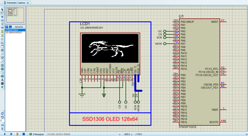
That’s all!
If you have any questions or suggestions don’t hesitate to leave a comment below