In this article, we’ll explore STM32 ADC & MPX4250AP Integration, focusing on how to interface the STM32 microcontroller with the MPX4250AP pressure sensor to achieve accurate pressure measurements

Things used in this project
Software apps and online services:
1- STMicroelectronics STM32CubeMX
2- STMicroelectronics STM32CubeIDE
3- Proteus 8
STM32 ADC and MPX4250AP Pressure Gauge Integration with UART and LCD for Interfacing
This project marks a significant advancement in system optimization through the integration of the STM32 ADC with the MPX4250AP Pressure Gauge. In the dynamic realm of embedded systems, precision and reliability stand as pillars of innovation. Leveraging the advanced microcontroller technology of the STM32 ADC alongside the cutting-edge pressure sensing capabilities of the MPX4250AP sensor, this project aims to elevate system performance to unparalleled levels.
General Description:
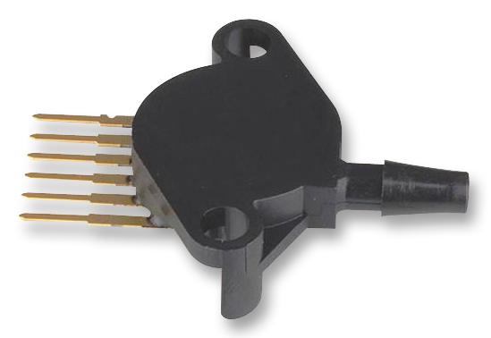
The MPX4250AP Pressure Gauge, tailored for intake manifold absolute pressure sensing in engine control systems, is engineered to perfection. Its piezoresistive transducer technology and patented silicon shear stress strain gauge ensure unparalleled accuracy and reliability. Designed to withstand extreme temperatures ranging from -40°C to +125°C, this sensor offers a maximum error rate of just 1.5% over a wide temperature range, making it an ideal choice for precision applications.

Typical Applications:
- Turbo Boost Engine Control: The integration of the STM32 ADC with the MPX4250AP Pressure Gauge facilitates precise regulation of turbocharger boost pressure, optimizing engine performance and efficiency. This application underscores the sensor’s crucial role in enhancing engine control and monitoring.
- On-Chip Temperature Compensation and Calibration: The sensor’s on-chip temperature compensation and calibration mechanisms ensure consistent performance across a wide temperature range, guaranteeing accurate pressure measurement in dynamic engine environments.
- Interface with Microprocessor-Based Systems: The MPX4250AP sensor’s compatibility with microprocessor-based systems, exemplified by the STM32 ADC, streamlines data acquisition and processing, enabling real-time monitoring and control of engine parameters.
To kickstart this project, we’ll begin by configuring ADC1 in regular conversion mode. Next, we’ll set Pins [PB3 .. PB9] as outputs for the display to showcase the pressure value. Lastly, we’ll establish UART communication to transmit system status updates
STM32CubeMX Configuration:
- Open CubeMX & Create New Project Choose The Target MCU STM32F103C6 & Double-Click Its Name
- Go To The Clock Configuration & Set The System Clock To 8MHz
Configuration for the ADC Mode:
- In the Categories tab, select the [ADC1, enable IN2]
- In the Parameter settings tab, ADC Settings : Enable Continuous Conversion Mode
- In the Parameter settings tab, ADC_Regular_Conversion Mode: [Enabler Regular Conversion Mode & Number of Conversio : 1 & External Trigger Conversion source : Regular Conversion launched by software & Rank1: channel : 2, sympling Time :1.5 Cycles]
Configuration for the GPIO Mode:
- Configure The GPIO Pins [PB3..PB5] as Output Pins (RS , EN , RW)
- Configure The GPIO Pins [PB6..PB9] as Output Pins (D4 , D5 , D6 , D7)
onfiguration for the UART Mode:
- Enable USART1 Module (Asynchronous Mode)
- Set the USART1 communication parameters (baud rate = 115200, parity=NON, stop bits =1, and word length =8bits)
- Generate The Initialization Code & Open The Project In CubeIDE
STM32CubeIDE Configuration:
- Write The Application Layer Code
- LiquidCrystal.h & LiquidCrystal.c => You’ll find the files in the STM32 LCD Interface for Multiple Displays
- main.c
/* Includes ------------------------------------------------------------------*/
#include "main.h"

/* Private includes ----------------------------------------------------------*/
/* USER CODE BEGIN Includes */
#include "LiquidCrystal.h"
#include"stdio.h"
#include"math.h"
/* USER CODE END Includes */

/* Private define ------------------------------------------------------------*/
/* USER CODE BEGIN PD */
/* Calibration Parameters */
#define ADC_RESOLUTION 4095     // 12-bit ADC resolution
#define ADC_VOLTAGE_RANGE 5.0f  // Voltage range of ADC in volts
#define PRESSURE_MIN 0.0        // Minimum pressure in kPa
#define VOLTAGE_MIN 0.25        // Corresponding minimum voltage in V
#define PRESSURE_MAX 250.0f     // Maximum pressure in kPa
#define VOLTAGE_MAX 4.87        // Corresponding maximum voltage in V

/* UART Message Strings */
#define MSG_OK "Operation successful.\n\r"
#define MSG_NOT_OK "Operation failed.\n\r"

/* Private variables ---------------------------------------------------------*/
ADC_HandleTypeDef hadc1;

UART_HandleTypeDef huart1;

/* USER CODE BEGIN PV */
/* Global Variables */
char uartMsg[50]; // UART message buffer
/* USER CODE END PV */

/* Private function prototypes -----------------------------------------------*/
void SystemClock_Config(void);
static void MX_GPIO_Init(void);
static void MX_USART1_UART_Init(void);
static void MX_ADC1_Init(void);

int main(void)
{
  /* USER CODE BEGIN 1 */
  float sensitivity = (PRESSURE_MAX - PRESSURE_MIN) / (VOLTAGE_MAX - VOLTAGE_MIN);
  float offset = PRESSURE_MIN - (sensitivity * VOLTAGE_MIN);
  float resolution = ADC_VOLTAGE_RANGE / ADC_RESOLUTION;
  /* USER CODE END 1 */


  /* Reset of all peripherals, Initializes the Flash interface and the Systick. */
  HAL_Init();

  /* Configure the system clock */
  SystemClock_Config();

  /* Initialize all configured peripherals */
  MX_GPIO_Init();
  MX_USART1_UART_Init();
  MX_ADC1_Init();

  /* USER CODE BEGIN 2 */
  LiquidCrystal(GPIOB, GPIO_PIN_3,GPIO_PIN_4,GPIO_PIN_5,GPIO_PIN_6 ,GPIO_PIN_7,GPIO_PIN_8,GPIO_PIN_9);
  begin(20,4);
  /* USER CODE END 2 */

  /* USER CODE BEGIN WHILE */
  while (1)
  {
    /* USER CODE END WHILE */

    /* USER CODE BEGIN 3 */
    HAL_ADC_Start(&hadc1);

    // Wait for the conversion to complete (timeout: 1 second)
    if (HAL_ADC_PollForConversion(&hadc1, 1000) != HAL_OK)
      HAL_UART_Transmit(&huart1, (uint8_t *)MSG_NOT_OK, sizeof(MSG_NOT_OK), 100);
    else
    {
     HAL_UART_Transmit(&huart1, (uint8_t *)MSG_OK, sizeof(MSG_OK), 100);
     // Read the ADC value
     int adc_value = HAL_ADC_GetValue(&hadc1);

     // Convert ADC value to pressure using calibration parameters
     float pressure_kPa = (adc_value * resolution * sensitivity) + offset;
     float pressure_mbar = pressure_kPa * 10; // Convert kPa to mbar

     setCursor(0, 0);
     print("Pressure Value=");
     setCursor(0, 1);
     sprintf(uartMsg, "%.1f", pressure_kPa);
     print(uartMsg);
     setCursor(7, 1);
     print("kPa");
     setCursor(0, 2);
     sprintf(uartMsg, "%.1f", pressure_mbar);
     print(uartMsg);
     setCursor(7, 2);
     print("Mbar");
     HAL_Delay(1000);
     clear();

    }
    HAL_ADC_Stop(&hadc1);
  }
  /* USER CODE END 3 */
}
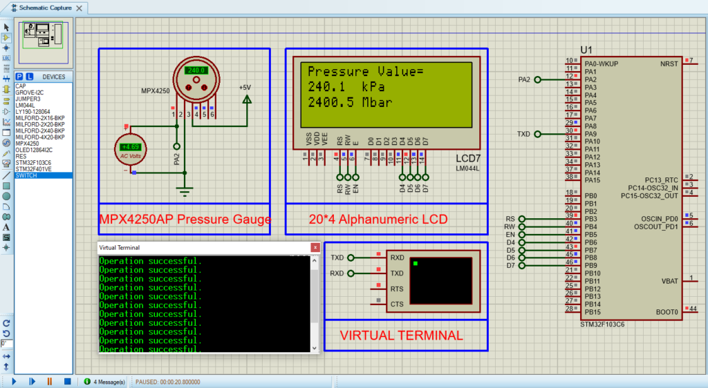
Proteus Configuration :
- Open Proteus & Create New Project and click next

- Click on Pick Device
- Search for STM32F103C6 & LCD 40×4 , MPX4250
- Click on Virtual Instruments Mode then choose VIRTUAL TERMINAL & AC VOLTMETRE
- Click on Terminal Mode then choose (DEFAULT & POWER &GROUND)
- finally make the circuit below and start the simulation

That’s all!
If you have any questions or suggestions don’t hesitate to leave a comment below
