
In this article, we will explore the MCP3008 SPI Interface STM32, detailing how to effectively connect the MCP3008 ADC to an STM32 microcontroller.
Software apps and online services:
1- STMicroelectronics STM32CubeMX
2- STMicroelectronics STM32CubeIDE
3- Proteus 8
STM32 Microcontroller Communication with MCP3008 ADC: SPI Interface for Analog Signal Acquisition:
In this project, we will explore how to use an STM32 microcontroller to communicate with an MCP3008 analog-to-digital converter (ADC) using the Serial Peripheral Interface (SPI) protocol.
MCP3008 ADC Features: Multiple Input Channels and 10-Bit Resolution:
The MCP3008 has 8 input channels, which means it can read up to 8 analog signals simultaneously. It has a resolution of 10 bits, which means it can convert analog signals into 1024 discrete digital values. The MCP3008 operates using a supply voltage of 2.7V to 5.5V, making it compatible with a wide range of microcontrollers and other digital devices.
MCP3008 ADC Communication via SPI Protocol: Interface Overview:
The MCP3008 ADC communicates with a microcontroller using SPI, which is a synchronous Serial Peripheral Interface . SPI uses a clock, data input, data output, and chip select (CS) line to transfer data between devices. The MCP3008 selects the input channel to read using the chip select line and sends the converted digital value back to the microcontroller using the data output line.
Overall, the MCP3008 is a useful component for projects that involve reading analog signals, such as temperature sensors, light sensors, or potentiometers. It is relatively easy to use and provides accurate digital readings of analog signals.
STM32CubeMX Configuration:
Open CubeMX & Create New Project Choose The Target MCU STM32F103C6 & Double-Click Its Name
- Go To The Clock Configuration & Set The System Clock To 8MHz
- Configure The GPIO Pins [PB3..PB9] as Output Pin (STM32 LCD Interface)
- Configure The GPIO Pin PA8 (CS) as Output Pin
- In the Categories tab, select the SPI1 & Full-Duplex Master
- Generate The Initialization Code & Open The Project In CubeIDE
STM32CubeIDE Configuration :
- Write The Application Layer Code
- LiquidCrystal.h & LiquidCrystal.c =>You’ll find the files in the STM32 LCD Interface for Multiple Display
- MCP3008.h & MCP3008.c
- main.c
/*
 * MCP3008.h
 *
 */

#ifndef MCP3008_MCP3008_H_
#define MCP3008_MCP3008_H_

#include "main.h"

typedef struct {
  GPIO_TypeDef* CS_PORT;
  uint16_t CS_PIN;
  SPI_HandleTypeDef* hspi;
}MCP3008_SPI;

void MCP3008_Init(MCP3008_SPI* spi, SPI_HandleTypeDef* hspi, GPIO_TypeDef* CS_PORT, uint16_t CS_PIN);
uint16_t MCP3008_Read_Channel(MCP3008_SPI* spi, uint8_t channel);

#endif /* MCP3008_MCP3008_H_ */
/*
 * MCP3008.c
 *
 */

#include "MCP3008.h"

/*
 * Set the MISO, MOSI, SCK and CS
 * SPI settings:
 * CPHA = 1 Edge
 * Prescaler = 8
 * First bit = MBS first
 * CPOL = Low
 */
void MCP3008_Init(MCP3008_SPI* spi, SPI_HandleTypeDef* hspi, GPIO_TypeDef* CS_PORT, uint16_t CS_PIN){
  spi->hspi = hspi;
  spi->CS_PORT = CS_PORT;
  spi->CS_PIN = CS_PIN;
}

// Read the channels from 0 to 7
uint16_t MCP3008_Read_Channel(MCP3008_SPI* spi, uint8_t channel){

    // Declare data that we will send
    uint8_t pTxData[3] = {0};
    pTxData[0] = ((0x01 << 7)|          // start bit
             (1 << 6)|            // SGL
             ((channel & 0x07) << 3));     // channel number
    pTxData[1] = 0x00;
    pTxData[2] = 0x00;

    // Data that we will get
    uint8_t pRxData[3] = {0};

    // CS low, Send and receive, CS high
    HAL_GPIO_WritePin(spi->CS_PORT, spi->CS_PIN, GPIO_PIN_RESET);
    HAL_SPI_TransmitReceive(spi->hspi, pTxData, pRxData, 3, 10);
    HAL_GPIO_WritePin(spi->CS_PORT, spi->CS_PIN, GPIO_PIN_SET);

    // Compute the ADC
return 0x3FF & ((pRxData[0] & 0x01) << 9 | (pRxData[1] & 0xFF) << 1 | (pRxData[2] & 0x80) >> 7);
}
#include "main.h"
#include "MCP3008.h"
#include "LiquidCrystal.h"
#include "stdio.h"

/* Private variables ---------------------------------------------------------*/
SPI_HandleTypeDef hspi1;

/* USER CODE BEGIN PV */
MCP3008_SPI spi_mpc3008;
uint16_t adc0,adc1,adc2,adc3;
char MSG_0[20];
char MSG_1[20];
char MSG_2[20];
char MSG_3[20];
float result_0,result_1,result_2,result_3;
/* USER CODE END PV */

int main(void)
{

  HAL_Init();
  SystemClock_Config();
  MX_GPIO_Init();
  MX_SPI1_Init();

  /* USER CODE BEGIN 2 */
MCP3008_Init(&spi_mpc3008, &hspi1, GPIOA, GPIO_PIN_8);
LiquidCrystal(GPIOB, GPIO_PIN_3,GPIO_PIN_4,GPIO_PIN_5,GPIO_PIN_6 ,GPIO_PIN_7,GPIO_PIN_8,GPIO_PIN_9);
begin(20, 4);
  /* USER CODE END 2 */

  while (1)
  {
    /* Read ADC's*/
       adc0 = MCP3008_Read_Channel(&spi_mpc3008, 0); // Channel 0
       adc1 = MCP3008_Read_Channel(&spi_mpc3008, 1); // Channel 1
       adc2 = MCP3008_Read_Channel(&spi_mpc3008, 2); // Channel 2
       adc3 = MCP3008_Read_Channel(&spi_mpc3008, 3); // Channel 3

      result_0 = (float)adc0;
      result_1 = (float)adc1;
      result_2 = (float)adc2;
      result_3 = (float)adc3;

      result_0=result_0/200;
      result_1=result_1/200;
      result_2=result_2/200;
      result_3=result_3/200;

      sprintf(MSG_0,"ADC0 Value = %.2f",result_0);
      setCursor(0,0);
      print(MSG_0);
      sprintf(MSG_1,"ADC1 Value = %.2f",result_1);
      setCursor(0,1);
      print(MSG_1);
      sprintf(MSG_2,"ADC2 Value = %.2f",result_2);
      setCursor(0,2);
      print(MSG_2);
      sprintf(MSG_3,"ADC3 Value = %.2f",result_3);
      setCursor(0,3);
      print(MSG_3);
}}
Proteus Configuration :
- Open Proteus & Create New Project and click next

- Click on Pick Device
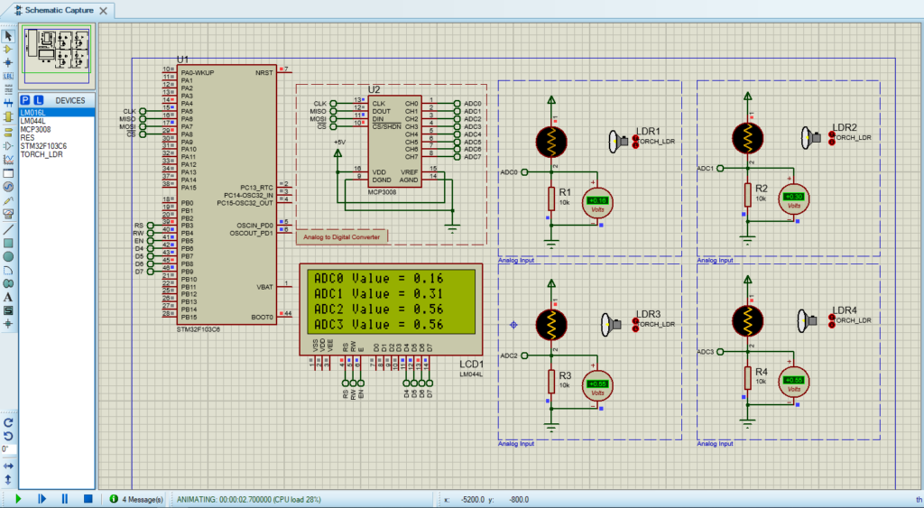
- Search for STM32F103C8 & MCP3008 & TORCH_LDR & RES
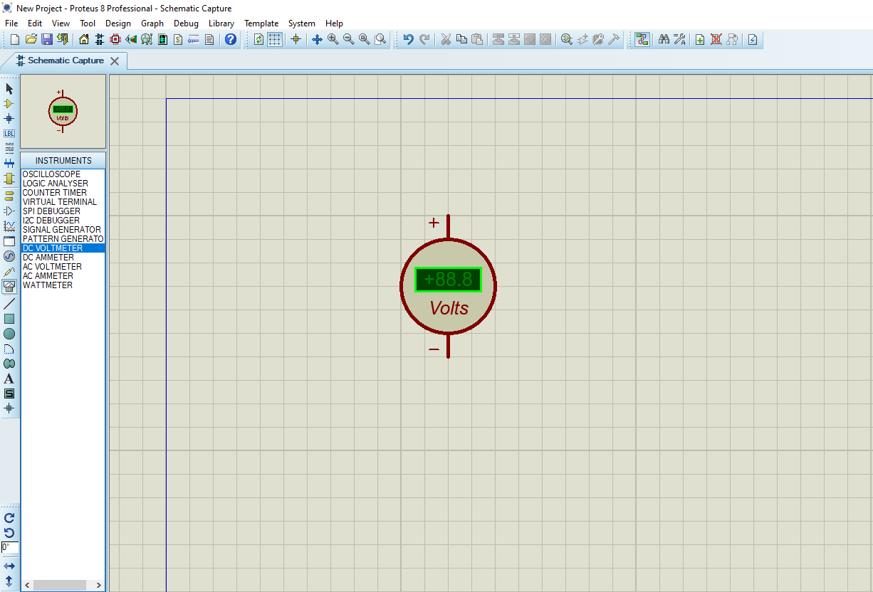
- Click on Virtual Instrumets Mode then choose DCVOLTMETER
- Click on Terminal Mode then choose (DYNAMIC&POWER &GROUND)
- finally make the circuit below and start the simulation
That’s all!
If you have any questions or suggestions don’t hesitate to leave a comment below
1 comment
During building I am getting warning
../Core/Src/LiquidCrystal.c:79:24: warning: variable ‘gpio_init’ set but not used [-Wunused-but-set-variable]
79 | GPIO_InitTypeDef gpio_init;
Is there any possibility to fix it ?