STM32 Sleep Modes: Exploring Energy-Saving Techniques

by Marwen Maghrebi

In this article, we explore STM32 Sleep Modes and their role in energy-saving techniques for microcontrollers. Understanding these modes helps optimize power consumption, making devices more efficient and longer-lasting

Things used in this project

Software apps and online services

1- STMicroelectronics STM32CubeMX

2- STMicroelectronics STM32CubeIDE

3- Proteus 8

STM32 Sleep Mode: Save Power and Extend Battery Life for Your Projects

Power management is a critical aspect of designing efficient and sustainable electronic devices. One of the most effective techniques for reducing power consumption in STM32 microcontrollers is STM32 Sleep Mode. This low-power state is designed to help you extend the battery life of your devices and manage power more effectively.

This guide will explore the mechanisms for entering and exiting Sleep Mode using the HAL library, describe different entry and exit methods, and offer practical tips for utilizing Sleep Mode in your STM32 projects.

UnderstandingSTM32Sleep Mode:

STM32 Sleep Mode is a power-saving state where the CPU halts its execution while keeping the microcontroller responsive to interrupts or events. It strikes a balance between power consumption and system responsiveness, making it ideal for situations where the microcontroller needs to be idle but still able to react to external signals.

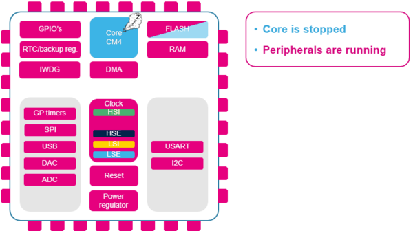
In Sleep mode, the CPU clock is off, but there is no effect on other clocks or analog clock sources. All peripherals continue to operate and can wake up the CPU when an interrupt or event occurs.

Entering STM32 Sleep Mode :

To enter STM32 Sleep Mode, you use the HAL_PWR_EnterSLEEPMode function provided by the HAL library. This function offers two options for how the microcontroller transitions into STM32 Sleep Mode:

  • WFI (Wait For Interrupt): When using the WFI instruction, the microcontroller goes into Sleep Mode and remains in this state until an interrupt is triggered. This is a simple and effective way to enter Sleep Mode if you expect to wake up based on interrupts from peripherals or external sources.
  • WFE (Wait For Event): When using the WFE instruction, the microcontroller enters Sleep Mode and waits for an event to occur. This mode is useful when you need the microcontroller to wake up in response to events without explicitly configuring interrupts.

Sleep Mode Entry Mechanisms :

  • Sleep-Now: If the SLEEPONEXIT bit is cleared in the Cortex®-M3 System Control register, the microcontroller enters STM32 Sleep Mode immediately after executing the WFI or WFE instruction. This is useful for scenarios where you want the microcontroller to go to Sleep Mode as soon as possible..
  • Sleep-on-Exit: If the SLEEPONEXIT bit is set, the microcontroller will enter STM32 Sleep Mode automatically when it finishes executing the current lowest priority Interrupt Service Routine (ISR). This is beneficial if you want the microcontroller to enter Sleep Mode after handling an interrupt without needing additional instructions

Exiting Sleep Mode:

The mechanism for exiting Sleep Mode depends on how the mode was entered:

  • If WFI was used: The microcontroller exits Sleep Mode when an interrupt is acknowledged by the Nested Vectored Interrupt Controller (NVIC). This means that any configured peripheral interrupt can wake the microcontroller from Sleep Mode and resume normal operation.
  • If WFE was used: The microcontroller exits Sleep Mode when a wake-up event occurs. This event can be generated in two main ways:
  1. Peripheral Interrupts: An interrupt from a peripheral can be configured to wake up the microcontroller. In this case, the SEVONPEND bit in the Cortex®-M3 System Control register must be enabled to wake the microcontroller on any pending events.
  2. EXTI Lines: External or internal EXTI lines configured in event mode can also wake up the microcontroller. This method leverages event lines to trigger wake-up without needing to clear the interrupt pending bits.

To kickstart this project, we’ll begin by configuring the STM32 microcontroller to enter Sleep Mode and wake up via UART. Specifically, we’ll set up the HAL_PWR_EnterSLEEPMode function to enable Sleep Mode, and configure the UART to handle communication and wake the microcontroller. This configuration will allow us to save power during idle periods and ensure the microcontroller can respond promptly to UART communication, thereby optimizing power management and system responsiveness.

STM32CubeMX Configuration:

  • Open CubeMX & Create New Project Choose The Target MCU STM32F103C6 & Double-Click Its Name
  • In Tab System Core Set High Speed Clock : Crystal/Ceramic Resonator
  • Go To The Clock Configuration & Set The System Clock To 32MHz

Configuration for the GPIO Mode:

  • Configure The GPIO Pins PB1 as Output Pin
  • Configure The GPIO Pins PB2 as Output Pin

Configuration for the UART Mode:

  • Enable USART1 Module (Asynchronous Mode)
  • Set the USART1 communication parameters (baud rate = 115200, parity=NON, stop bits =1, and word length = 8bits)
  • In the NVIC settings tab, enable the interrupt for the USART1 peripheral

Configuration for the HAL Settings:

  • Set all Free pins as Analogs (to optimize the power consumption )
  • Generate The Initialization Code & Open The Project In CubeIDE

STM32CubeIDE Configuration:

  • Write The Application Layer Code
  • main.c
/* USER CODE END Header */
/* Includes ------------------------------------------------------------------*/
#include "main.h"

/* Private includes ----------------------------------------------------------*/
/* USER CODE BEGIN Includes */
#include "stdio.h"
#include "string.h"
/* USER CODE END Includes */

/* Private define ------------------------------------------------------------*/
/* USER CODE BEGIN PD */
#define LED_Pin GPIO_PIN_1
#define LED_Pin2 GPIO_PIN_2
#define LED_GPIO_Port GPIOB
/* USER CODE END PD */

/* Private variables ---------------------------------------------------------*/
UART_HandleTypeDef huart1;

/* Private function prototypes -----------------------------------------------*/
void SystemClock_Config(void);
static void MX_GPIO_Init(void);
static void MX_USART1_UART_Init(void);
/* USER CODE BEGIN PFP */

/* Private user code ---------------------------------------------------------*/
/* USER CODE BEGIN 0 */
uint8_t Rx_data;
char * str;

void HAL_UART_RxCpltCallback(UART_HandleTypeDef *huart)
{
    if (huart->Instance == USART1) {
        str = "WakeUP from SLEEP by UART\r\n";
        HAL_UART_Transmit(&huart1, (uint8_t*) str, strlen(str), HAL_MAX_DELAY);

        // Re-enable the UART receive interrupt
        HAL_UART_Receive_IT(&huart1, &Rx_data, 1);
        HAL_PWR_DisableSleepOnExit();
    }
}

/* USER CODE END 0 */

int main(void)
{

  /* Reset of all peripherals, Initializes the Flash interface and the Systick. */
  HAL_Init();
  /* Configure the system clock */
  SystemClock_Config();
  /* Initialize all configured peripherals */
  MX_GPIO_Init();
  MX_USART1_UART_Init();
  /* USER CODE BEGIN 2 */
  HAL_UART_Receive_IT(&huart1, &Rx_data, sizeof(Rx_data));  // Enable UART receive interrupt
  /* USER CODE END 2 */

  /* USER CODE BEGIN WHILE */
  while (1)
  {
    /* USER CODE END WHILE */
    /* USER CODE BEGIN 3 */
    str = "Entering into SLEEP MODE in 5 seconds\r\n";
    HAL_UART_Transmit(&huart1, (uint8_t*) str, strlen(str), HAL_MAX_DELAY);
    HAL_GPIO_WritePin(LED_GPIO_Port, LED_Pin, RESET);
    HAL_GPIO_WritePin(LED_GPIO_Port, LED_Pin2,RESET);
    HAL_Delay(5000);

    HAL_SuspendTick();
    HAL_PWR_EnableSleepOnExit();

    HAL_GPIO_WritePin(LED_GPIO_Port, LED_Pin, SET);
    str = "SLEEP MODE is active \r\n";
    HAL_UART_Transmit(&huart1, (uint8_t*) str, strlen(str), HAL_MAX_DELAY);

    HAL_PWR_EnterSLEEPMode(PWR_MAINREGULATOR_ON, PWR_SLEEPENTRY_WFI);
    HAL_ResumeTick();

    str = "WakeUP from SLEEP\r\n";
    HAL_UART_Transmit(&huart1, (uint8_t*) str, strlen(str), HAL_MAX_DELAY);
    HAL_GPIO_WritePin(LED_GPIO_Port, LED_Pin, RESET);
    for (int i = 0; i < 20; i++) {

        HAL_GPIO_TogglePin(LED_GPIO_Port, LED_Pin2);
        HAL_Delay(100);
    }
  }
  /* USER CODE END 3 */
}

Proteus Configuration :

  • Open Proteus & Create New Project and click next

  • Click on Pick Device
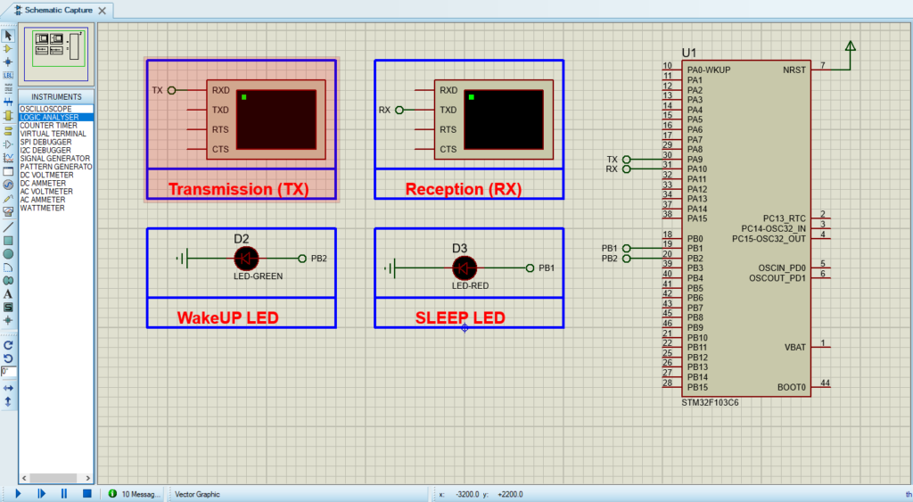
  • Search for STM32F103C6 & LED-RED & LED-GREEN
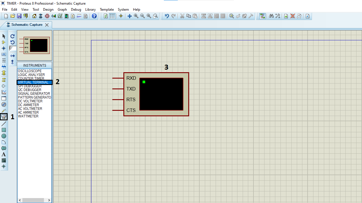
  • Click on Virtual Instruments Mode then choose Terminal

  • Click on Terminal Mode then choose (DEFAULT & POWER &GROUND)
  • finally make the circuit below and start the simulation
Proteus simulation circuit design for STM32 Sleep Modes.

That’s all!
If you have any questions or suggestions don’t hesitate to leave a comment below

You Might Also Like

Leave a Comment


Are you sure want to unlock this post?
Unlock left : 0
Are you sure want to cancel subscription?
-
00:00
00:00
Update Required Flash plugin
-
00:00
00:00