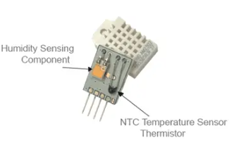
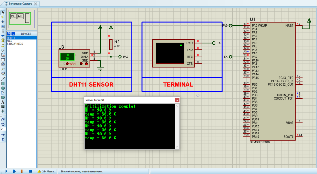
DHT11 Sensor with STM32: A Complete Integration Guide

by Marwen Maghrebi

This article covers the integration of the DHT11 Sensor with STM32 microcontrollers. We’ll provide a concise guide on setting up the DHT11 for accurate temperature and humidity measurements

Things used in this project

Software apps and online services:

1- STMicroelectronics STM32CubeMX

2- STMicroelectronics STM32CubeIDE

3- Proteus 8

DHT11 Sensor with STM32: Temperature and Humidity Measurement

The DHT11 Temperature and Humidity Sensor is a cost-effective solution for measuring environmental conditions. It combines a temperature sensor and a humidity sensor into a single module, providing calibrated digital outputs. 

This article explores the functionality, technical specifications, and integration of the DHT11 sensor with an STM32 microcontroller for reliable environmental monitoring.

Sensor Components and Operation in DHT11 Sensor with STM32

Internal Components

The DHT11 sensor module includes:

  • NTC Thermistor: Measures temperature by decreasing resistance as temperature increases, following a negative temperature coefficient (NTC) characteristic.
  • Humidity-Sensing Component: Utilizes a moisture-sensitive capacitor to measure relative humidity. The capacitor’s capacitance changes with moisture levels in the air.
  • Microcontroller: Manages data acquisition, processing, and transmission via the 1-Wire digital protocol.
DHT11 Sensor with STM32 featuring NTC Temperature Sensor and Humidity Sensing Component

Temperature Sensing

The DHT11 uses an NTC thermistor to sense temperature. The thermistor’s resistance decreases with rising temperature. The internal microcontroller calculates the temperature value using the thermistor’s characteristic curve and transmits this data digitally over the 1-Wire data line, updated every second.

Humidity Sensing

Humidity is measured using a moisture-sensitive capacitor. The internal microcontroller measures the capacitor’s charging and discharging times to determine its capacitance. This capacitance is converted into a digital signal and sent via the 1-Wire interface, with the relative humidity (RH%) calculated based on this capacitance.

Technical Specifications

Communication Protocol of DHT11 Sensor with STM32

Single-Wire Interface

The DHT11 communicates using a single-wire protocol with a 40-bit data format:

  • 8-bit Integral RH Data
  • 8-bit Decimal RH Data
  • 8-bit Integral Temperature Data
  • 8-bit Decimal Temperature Data
  • 8-bit Checksum

A full data transmission takes about 4 milliseconds, with data sent from highest to lowest bits.

Communication Process

  • Start Signal: The MCU initiates communication by sending a start signal to switch the DHT11 from low-power mode to active mode, lasting at least 18 milliseconds.
  • Response Signal: The DHT11 responds with an 80-microsecond low-voltage signal, followed by a high-voltage signal to prepare for data transmission.
  • Data Transmission: Each data bit starts with a 50-microsecond low-voltage pulse, with the subsequent high-voltage pulse length indicating whether the bit is “0” or “1”.

Applications

The DHT11 sensor is versatile and applicable in various fields:

  • Home Automation: Adjusts temperature and humidity for comfort.
  • Weather Monitoring: Enhances weather forecasting accuracy.
  • Agriculture: Optimizes greenhouse and crop field conditions.
  • Industrial Control: Ensures proper operation of HVAC and refrigeration systems.
  • Medical: Maintains safe conditions in medical devices like incubators.

To integrate the DHT11 sensor with an STM32 microcontroller, configure GPIO pins and the TIM1 timer for precise timing. The code initializes peripherals, sends a start signal to the sensor, verifies its response, and reads data bytes. It then processes and transmits the sensor data via UART for real-time monitoring. This approach demonstrates how to effectively interface the DHT11 with an STM32 to achieve accurate temperature and humidity measurements.

STM32CubeMX Configuration:

  • Open CubeMX & Create New Project Choose The Target MCU STM32F103C6 & Double-Click Its Name
  • Go To The Clock Configuration & Set The System Clock To 16MHz

Configuration for the GPIO Mode:

  • Configure The GPIO Pins PA0 as Output Pin

Configuration for the TIMER Mode:

  • In the Categories tab, select the TIM1
  • Enable Internal Clock
  • In the Parameter settings tab, set the (Prescaler=15 & Counter Peroid 65535) 

Configuration for the UART Mode:

  • Enable USART1 Module (Asynchronous Mode)
  • Set the USART1 communication parameters (baud rate = 115200, parity=NON, stop bits =1, and word length = 8bits)
  • Generate The Initialization Code & Open The Project In CubeIDE

STM32CubeIDE Configuration:

  • Write The Application Layer Code
  • main.c
/* Includes ------------------------------------------------------------------*/
#include "main.h"

/* Private includes ----------------------------------------------------------*/
/* USER CODE BEGIN Includes */
#include<string.h>
#include<stdio.h>

/* Private define ------------------------------------------------------------*/
/* USER CODE BEGIN PD */
#define DHT11_Pin GPIO_PIN_0
#define DHT11_GPIO_Port GPIOA
/* USER CODE END PD */

/* Private variables ---------------------------------------------------------*/
TIM_HandleTypeDef htim1;

UART_HandleTypeDef huart1;

/* USER CODE BEGIN PV */
char msg[50] ;
char message1[16];
char message1[16];
uint8_t TOUT =0 , CheckSum , i;
uint8_t T_Byte1 , T_Byte2 , RH_Byte1 , RH_Byte2 ;

/* USER CODE END PV */


/* Private function prototypes -----------------------------------------------*/
void SystemClock_Config(void);
static void MX_GPIO_Init(void);
static void MX_TIM1_Init(void);
static void MX_USART1_UART_Init(void);
/* USER CODE BEGIN PFP */

/* USER CODE BEGIN 0 */
void start_signal (void){
     GPIO_InitTypeDef GPIO_InitStruct = {0};


      GPIO_InitStruct.Pin = DHT11_Pin;
      GPIO_InitStruct.Mode = GPIO_MODE_OUTPUT_PP;
      GPIO_InitStruct.Pull = GPIO_NOPULL;
      GPIO_InitStruct.Speed = GPIO_SPEED_FREQ_LOW;
      HAL_GPIO_Init(DHT11_GPIO_Port, &GPIO_InitStruct);

      HAL_GPIO_WritePin(DHT11_GPIO_Port, DHT11_Pin, GPIO_PIN_RESET);
      HAL_Delay(18);
      HAL_GPIO_WritePin(DHT11_GPIO_Port, DHT11_Pin, GPIO_PIN_SET);
      delay_us(30);

      GPIO_InitStruct.Mode = GPIO_MODE_INPUT;
      HAL_GPIO_Init(DHT11_GPIO_Port, &GPIO_InitStruct);

}

void delay_us ( uint16_t us)
{
    __HAL_TIM_SET_COUNTER(&htim1,0);
    while(__HAL_TIM_GET_COUNTER(&htim1) < us);
}

uint8_t check_response(void){
    TOUT=0;
    __HAL_TIM_SET_COUNTER(&htim1,0);
    while(!HAL_GPIO_ReadPin(DHT11_GPIO_Port, DHT11_Pin) && (__HAL_TIM_GET_COUNTER(&htim1) < 100)) {};
    if(__HAL_TIM_GET_COUNTER(&htim1)>= 100){
        return 0; //timeout
    }
    while(HAL_GPIO_ReadPin(DHT11_GPIO_Port, DHT11_Pin) && (__HAL_TIM_GET_COUNTER(&htim1) < 100)) {};
        if(__HAL_TIM_GET_COUNTER(&htim1)>= 100){
            return 0; //timeout
        }
    return 1;
}

uint8_t read_byte(void){
    uint8_t num =0 ;
    for(i=0 ;i<8; i++){
        while(!HAL_GPIO_ReadPin(DHT11_GPIO_Port, DHT11_Pin))  {};
        __HAL_TIM_SET_COUNTER(&htim1,0);
        while(HAL_GPIO_ReadPin(DHT11_GPIO_Port, DHT11_Pin))  {};
        if(__HAL_TIM_GET_COUNTER(&htim1) > 40)
        {
            num |= (1 << (7 - i));
        }

    }
    return num;
}

void process_sensor_data(void){
    RH_Byte1 = read_byte();
    RH_Byte2 = read_byte();
    T_Byte1 = read_byte();
    T_Byte2 = read_byte();
    CheckSum = read_byte();

    uint8_t humidity_integer =  RH_Byte1 ;
    uint8_t humidity_decimal =  RH_Byte2 / 10 ;

    uint8_t temperature_integer =  T_Byte1 ;
    uint8_t temperature_decimal =  T_Byte2 / 10 ;

    if(CheckSum ==((RH_Byte1+RH_Byte2 +T_Byte1+T_Byte2)& 0xff)){
        snprintf(msg,sizeof(msg),"RH = %d.%d %%\r\n",humidity_integer,humidity_decimal);
        send_uart_message(msg);
        snprintf(msg,sizeof(msg),"temp = %d.%d C\r\n",temperature_integer,temperature_decimal);
        send_uart_message(msg);

    }else
    {
        send_uart_message("Checksum Errors ! Trying Again ...\r\n");
    }
}

void send_uart_message(char *messsage){
    HAL_UART_Transmit(&huart1, (uint8_t*)messsage, strlen(messsage), HAL_MAX_DELAY);
}
/* USER CODE END 0 */

int main(void)
{

  /* Reset of all peripherals, Initializes the Flash interface and the Systick. */
  HAL_Init();
  /* Configure the system clock */
  SystemClock_Config();
  /* Initialize all configured peripherals */
  MX_GPIO_Init();
  MX_TIM1_Init();
  MX_USART1_UART_Init();
  /* USER CODE BEGIN 2 */
 HAL_TIM_Base_Start(&htim1);
 send_uart_message("Initilization complet \n\r");
  /* USER CODE END 2 */

  /* Infinite loop */
  /* USER CODE BEGIN WHILE */
  while (1)
  {
    /* USER CODE END WHILE */

    /* USER CODE BEGIN 3 */
      HAL_Delay(1000); // 1 second delay before starting
      start_signal();
      uint8_t check = check_response();
      if (!check){
          send_uart_message("No responce from the sensor \r\n");
      } else {
          process_sensor_data();
      }

  }
  /* USER CODE END 3 */
}

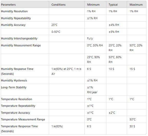
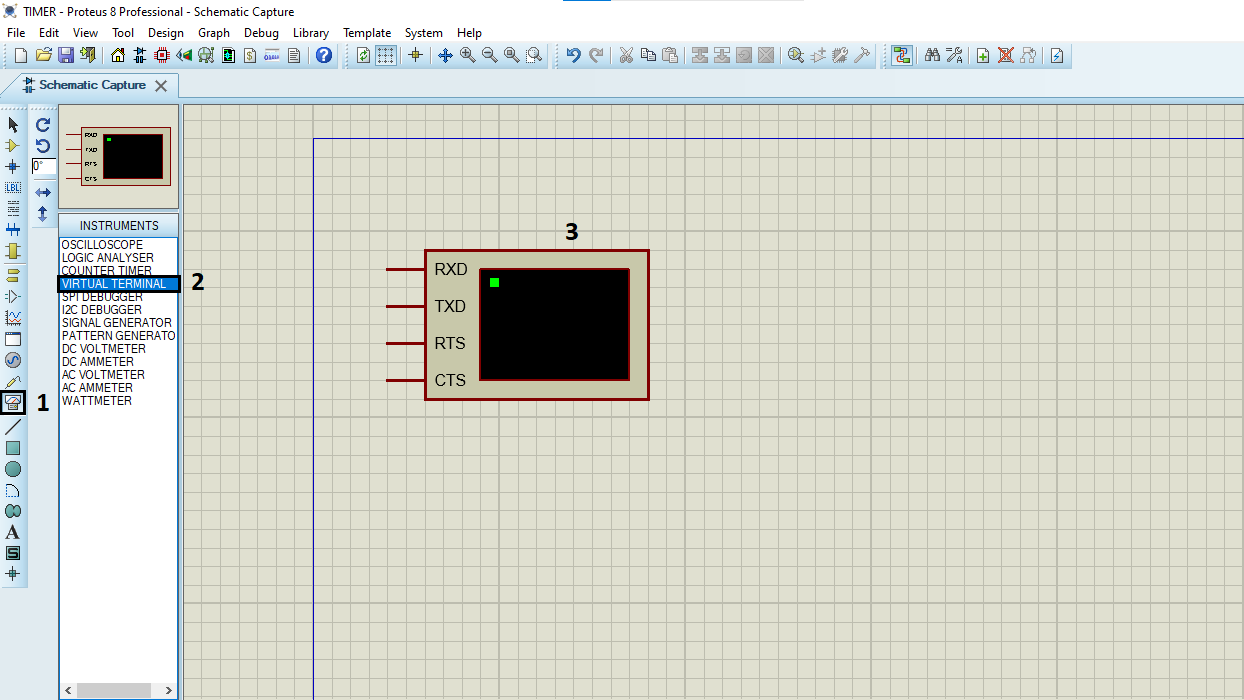
Proteus Configuration :

  • Open Proteus & Create New Project and click next

  • Click on Pick Device
  • Search for STM32F103C6 & RES & DHT11
  • Click on Virtual Instruments Mode then choose Terminal

  • Click on Terminal Mode then choose (DEFAULT & POWER &GROUND)
  • finally make the circuit below and start the simulation
Circuit diagram showing the integration of DHT11 Sensor with STM32 microcontroller.

That’s all!
If you have any questions or suggestions don’t hesitate to leave a comment below

You Might Also Like

1 comment

STM32 with DHT22: Interfacing Temperature and Humidity Sensor - The Embedded Things September 25, 2024 - 6:46 pm

[…] the DHT22 with an STM32 microcontroller. This guide builds on our previous integration of the DHT11 sensor, highlighting the differences and advantages of using the […]

Reply

Leave a Comment


Are you sure want to unlock this post?
Unlock left : 0
Are you sure want to cancel subscription?
-
00:00
00:00
Update Required Flash plugin
-
00:00
00:00