Table of Contents
In this article, we delve into the intricacies of using the UART and 74HC595 7-Segment Display to control a 7-segment display. We explore the configuration and integration of the 74HC595 Shift Register within embedded systems, specifically focusing on how to efficiently utilize UART communication to cycle through numbers 0 to 9. This approach not only demonstrates the power and flexibility of the 74HC595 but also showcases how to achieve precise control of multiple 7-segment displays through UART.
7-Segment Display :
The 7-segment display, a ubiquitous component in electronics, offers a simple yet effective means of visualizing numerical data. Comprising seven segments arranged in a pattern resembling the number “8,” each segment can be independently illuminated to represent numeric digits ranging from 0 to 9.
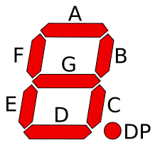
Its straightforward design makes it a popular choice for displaying numeric information in various applications, from digital clocks and timers to electronic meters and counters.
Exploring the 74HC595 Shift Register :
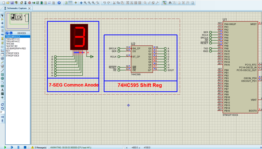
The 74HC595 Shift Register serves as a fundamental element in expanding GPIO capabilities for driving multiple 7-segment displays within our project. We offer a comprehensive insight into its operational principles, emphasizing its serial-in, parallel-out architecture. Moreover, we highlight its effectiveness in driving a common anode 7-segment display, showcasing its adaptability and efficiency in our project setup.
To kickstart this project, we’ll begin by configuring the GPIO pins (PA3 to PA7) as output pins. Specifically, we define the following pins: SER (PA3), RCLK (PA4), SRCLK (PA5), OE (PA6), and SRCLR (PA7). These definitions set the groundwork for our interface, allowing the microcontroller to communicate effectively with the 74HC595 Shift Register.
Next, we’ll delve into setting up the interface, focusing on using a counter to cycle through numbers 0 to 9 and display them on the 7-segment display. This approach demonstrates how to efficiently and effectively use the 74HC595 Shift Register in embedded systems.
Proteus Configuration :
- Open Proteus & Create New Project and click next

- Click on Pick Device
- Search for STM32F103C6 & 74HC595 & 7-SEG
- Click on Virtual Instruments Mode then choose
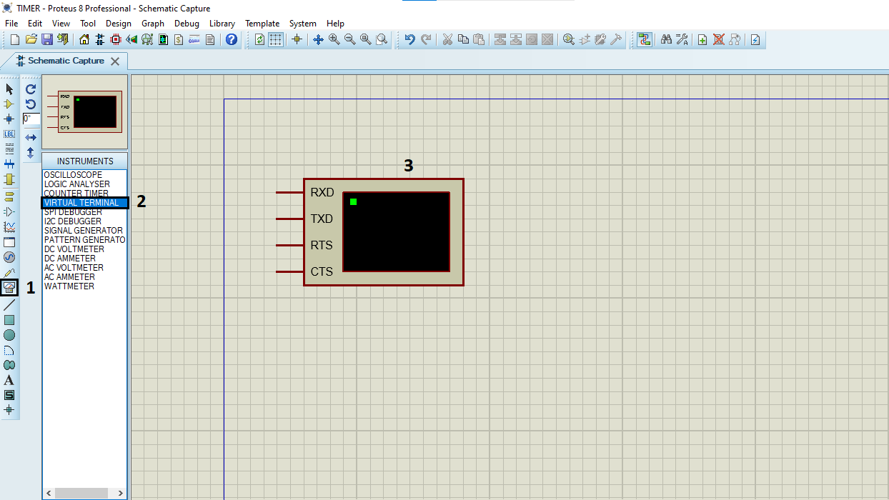
- Click on Terminal Mode then choose (DEFAULT & POWER &GROUND)