
Things used in this project
Software apps and online services:
1- STMicroelectronics STM32CubeMX
2- STMicroelectronics STM32CubeIDE
3- Proteus 8
Optimizing STM32 Microcontroller Integration with DC Motors using Advanced Techniques and Motor Driver ICs
This project focuses on the seamless integration of STM32 microcontrollers with DC motors, utilizing advanced techniques such as timers, PWM, ADC, and popular motor driver ICs including L289n and L293D.
L289n Motor Driver IC Overview: Dual H-Bridge Functionality and Operating Requirements:
The L289n, a dual H-bridge motor driver IC, empowers independent control over two DC motors or a single stepper motor. With a maximum current rating of approximately 1A per motor channel, it proves suitable for driving small to medium-sized DC motors. External control logic, such as microcontrollers or discrete logic circuits, is necessary to provide signals for motor direction and enable functions. Additionally, an external power supply ranging from 4.5V to 36V is required for proper motor operation.
L293D Motor Driver IC Overview: Dual H-Bridge Functionality and Built-in Control Logic:
Similarly, the L293D, another dual H-bridge motor driver IC, excels in independent control of two DC motors or a single stepper motor. It boasts a maximum current rating of around 600mA per motor channel, making it well-suited for low to medium power motors. Notably, the L293D features built-in control logic, enabling direct interfacing with TTL or CMOS logic levels. This streamlines the control circuitry by eliminating the need for additional external logic components. Furthermore, the L293D incorporates an internal voltage regulator, eliminating the requirement for a separate voltage regulator and allowing operation at lower voltage levels (typically 4.5V to 36V).
The Role of PWM in Optimizing L298N and L293D Motor Driver IC Performance:
Significantly, PWM assumes a critical role in optimizing the performance of the L298N and L293D motor driver ICs. PWM facilitates precise motor speed control, enhances power efficiency, reduces motor vibrations, and ensures compatibility. The modulation of the PWM signal enables smooth and accurate adjustments to the motor’s speed, maximizing energy efficiency and prolonging the motor’s lifespan. By minimizing motor vibrations through PWM modulation, stable and reliable motor operation is achieved. As the L298N and L293D motor driver ICs are designed to effectively work with PWM signals, integrating PWM is imperative to harness the full potential of these motor driver ICs.
By skillfully incorporating timers, PWM, ADC, and the L289n and L293D motor driver ICs, this project unlocks a comprehensive approach to integrating STM32 microcontrollers with DC motors. The result is a precise motor control, efficient power utilization, minimized vibrations, and seamless compatibility, empowering a wide range of applications requiring optimal motor performance.
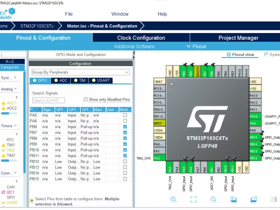
STM32CubeMX Configuration:
Open CubeMX & Create New Project Choose The Target MCU STM32F103C6 & Double-Click Its Name
- Go To The Clock Configuration & Set The System Clock To 8MHz
GPIO Configuration:
- Configure The GPIO Pin PA6 (slection pin)
- Configure The GPIO Pins [PB6..PB11] (Control Buttons)
- Configure The GPIO Pins [PB14, PB15] and PA3 (L298 Motor Driver)
- Configure The GPIO Pins [PB12, PB13] and PA2 (L293D Motor Driver)
TIMER Configuration:
- In the Categories tab, select the TIM2 then (enable Internal Clock & PWM Generation channel 3 and channel 4)
- In the Parameter settings tab, set the (Prescaler = 800 & Counter Peroid = 1000)
- set the Pulse to 500 & enable the output compare preload for (PWM Generation ch3 and ch4)
ADC Configuration:
- In the Categories tab, select the ADC1 & enable IN9
- In the Parameter settings tab, Enable the Continuous Conversion Mode
UART Configuration:
- Enable USART1 Module (Asynchronous Mode)
- Set the USART1 communication parameters (baud rate = 9600, parity=NON, stop bits =1, and word length =8bits)
- Generate The Initialization Code & Open The Project In CubeIDE
STM32CubeIDE Configuration :
In file name :main.c
#include "main.h"
#include"stdio.h"

ADC_HandleTypeDef hadc1;
TIM_HandleTypeDef htim2;
UART_HandleTypeDef huart1;

void SystemClock_Config(void);
static void MX_GPIO_Init(void);
static void MX_TIM2_Init(void);
static void MX_ADC1_Init(void);
static void MX_USART1_UART_Init(void);

int main(void)
{
    /* USER CODE BEGIN 1 */
    uint16_t readValue;
    int speed;
    char str[20];
    /* USER CODE END 1 */
    HAL_Init();
    MX_GPIO_Init();
    MX_TIM2_Init();
    MX_ADC1_Init();
    MX_USART1_UART_Init();

    /* USER CODE BEGIN 2 */
    HAL_ADC_Start(&hadc1); //PB1
    HAL_TIM_Base_Start(&htim2); //Initialize stm32 timer 3
    HAL_TIM_PWM_Start(&htim2,TIM_CHANNEL_3); //Start pwm second motor 100% duty cycle
    /* USER CODE END 2 */

while (1)
{
  switch(HAL_GPIO_ReadPin(GPIOA, GPIO_PIN_6))
  {
  case GPIO_PIN_SET: // L298 Drive Motor
     HAL_TIM_PWM_Start(&htim2,TIM_CHANNEL_4);
     HAL_ADC_PollForConversion(&hadc1,1000);
     readValue = HAL_ADC_GetValue(&hadc1);
     readValue = (readValue<<4);
     sprintf(str,"ADC value =  %u ", readValue);
     HAL_UART_Transmit(&huart1,(uint8_t*)str, sizeof(str),100);
     HAL_UART_Transmit(&huart1,(uint8_t*)&"\n\r",2,2);
     HAL_Delay(200);
    if (readValue < 1872) {
        HAL_GPIO_WritePin(GPIOB, GPIO_PIN_14, 0);
        HAL_GPIO_WritePin(GPIOB, GPIO_PIN_15, 1);
        speed = (readValue - 1800) * (-1) ;
    } else if (readValue > 1900) {
        HAL_GPIO_WritePin(GPIOB, GPIO_PIN_15, 0);
        HAL_GPIO_WritePin(GPIOB, GPIO_PIN_14, 1);
        speed = (readValue - 1800) ;
    } else {
        speed = 0;
        }
        __HAL_TIM_SET_COMPARE(&htim2,TIM_CHANNEL_4, speed);
        HAL_Delay(50);
    break;
case GPIO_PIN_RESET: // L293D Drive Motor
    //STOP L298 Drive Motor
    HAL_GPIO_WritePin(GPIOB, GPIO_PIN_14, 0);
    HAL_GPIO_WritePin(GPIOB, GPIO_PIN_15, 0);
    if(HAL_GPIO_ReadPin(GPIOB,GPIO_PIN_6)==GPIO_PIN_RESET)
    {
        HAL_GPIO_WritePin(GPIOB,GPIO_PIN_12,0);
        HAL_GPIO_WritePin(GPIOB,GPIO_PIN_13,0);
        HAL_GPIO_WritePin(GPIOB,GPIO_PIN_14,0);
        HAL_GPIO_WritePin(GPIOB,GPIO_PIN_15,0);
    }
    //Clockwise
    if(HAL_GPIO_ReadPin(GPIOB,GPIO_PIN_7)==GPIO_PIN_RESET)
    {
        HAL_GPIO_WritePin(GPIOB,GPIO_PIN_12,1);
        HAL_GPIO_WritePin(GPIOB,GPIO_PIN_13,0);
    }
    //AntiClockwise
    if(HAL_GPIO_ReadPin(GPIOB,GPIO_PIN_8)==GPIO_PIN_RESET)
    {
        HAL_GPIO_WritePin(GPIOB,GPIO_PIN_12,0);
        HAL_GPIO_WritePin(GPIOB,GPIO_PIN_13,1);
    }
    //Motor rotate at 25% duty cycle
    if(HAL_GPIO_ReadPin(GPIOB,GPIO_PIN_9)==GPIO_PIN_RESET)
    {
        __HAL_TIM_SET_COMPARE(&htim2,TIM_CHANNEL_3,25); //Second motor 25% voltage
    }
    //Motor rotate at 50% duty cycle
    if(HAL_GPIO_ReadPin(GPIOB,GPIO_PIN_10)==GPIO_PIN_RESET)
    {
        __HAL_TIM_SET_COMPARE(&htim2,TIM_CHANNEL_3,50); //Second motor 50% voltage
    }
    //Motor rotate at 75% duty cycle
    if(HAL_GPIO_ReadPin(GPIOB,GPIO_PIN_11)==GPIO_PIN_RESET)
    {
        __HAL_TIM_SET_COMPARE(&htim2,TIM_CHANNEL_3,75); //Second motor 75% voltage
    }
    break;
  default:
// Handle any unexpected cases
    break;
    }
  }
}
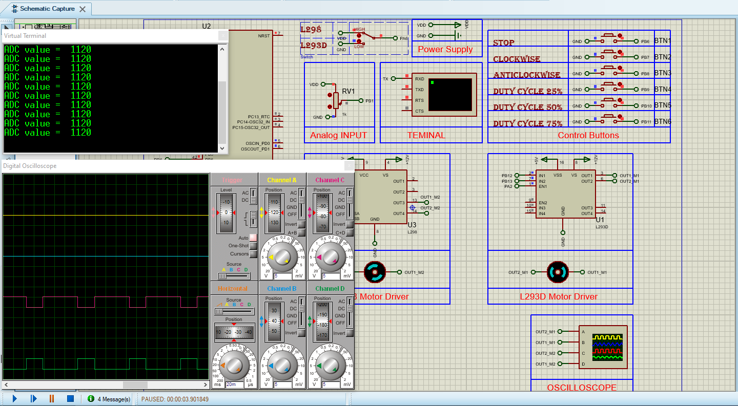
Proteus Configuration :
- Open Proteus & Create New Project and click next

- Click on Pick Device
- Search for STM32F103C6 & L298 & L293D & Motor & Button & Pot & RES & SW-SPDT
- Click on Virtual Instruments Mode then choose (VIRTUAL TERMINAL&OSCILLOSCOPE)
- Click on Terminal Mode then choose (DEFAULT & POWER &GROUND)
- finally make the circuit below and start the simulation
That’s all!
If you have any questions or suggestions don’t hesitate to leave a comment below