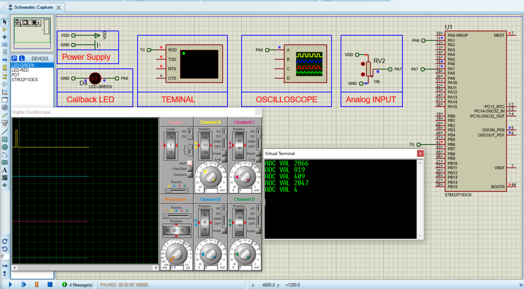
Advanced Analog-to-Digital Conversion STM32: TIMER Trigger

by Marwen Maghrebi

Things used in this project

Software apps and online services:

1- STMicroelectronics STM32CubeMX

2- STMicroelectronics STM32CubeIDE

3- Proteus 8

Exploring ADC and Timer Trigger Integration in STM32

This project focuses on exploring how to combine ADC and TIMER Trigger functionalities in STM32 microcontrollers, with a specific focus on Timer Trigger Out Events. Discover how these features work together to achieve precise timing control, complementing ADC operations effortlessly. Through simple experiments and clear analysis, uncover the efficiency, flexibility, and real-time processing capabilities that come with this integrated approach in STM32 microcontrollers.

Efficient Integration of ADC and TIMER Trigger Functionalities:

In the world of embedded development, merging ADC and TIMER triggers becomes essential, allowing synchronized timing control with external events while efficiently acquiring analog data. This synchronization boosts system efficiency and enables seamless coordination of tasks, responding swiftly to dynamic input signals. From industrial automation to smart devices, this integrated approach offers versatility, ensuring optimal performance across various applications.

Initial Configuration Steps for Timer and ADC Setup:

To start this project, we’ll first configure the TIMER peripheral to generate PWM signals without any output. We’ll adjust the counter settings to achieve a period of 10 seconds.Next, we’ll set up the ADC conversion in regular mode, with the external conversion source being the timer trigger event. Lastly, for interfacing, we’ll configure UART communication to transmit the ADC readings and system status.

STM32CubeMX Configuration:

  • Open CubeMX & Create New Project Choose The Target MCU STM32F103C6 & Double-Click Its Name
  • Go To The Clock Configuration & Set The System Clock To 8MHz

Configuration for the GPIO Mode:

  • Configure GPIO Pins PA1 indicating the callback notifications.

Configuration for the TIMER Mode:

  • In the Categories tab, select the TIM3 then (enable Internal Clock & One Pulse Mode & PWM Generation Channel 1)
  • In the Counter settings tab, set the (Prescaler = 10000 & Counter Peroid = 8000) The purpose of this settings is to generate a periodic time event with a 10sec.

  • In the Trigger Output tab, set the Trigger Event to Update Event
  • In the PWM Generation tab, set Mode PWM mode 1

Configuration for the ADC Mode:

  • In the Categories tab, select the [ADC1, enable IN7]
  • In the Parameter settings tab, Enabler Regular Conversion Mode
  • In the NVIC settings tab, Enable ADC1 and ADC2 global Interrupts

Configuration for the UART Mode:

  • Enable USART1 Module (Asynchronous Mode)
  • Set the USART1 communication parameters (baud rate = 115200, parity=NON, stop bits =1, and word length =8bits)
  • Generate The Initialization Code & Open The Project In CubeIDE
  • Write The Application Layer Code

STM32CubeIDE Configuration :

In file name : main.c

#include "main.h"
#include<stdio.h>
ADC_HandleTypeDef hadc1;
TIM_HandleTypeDef htim3;
UART_HandleTypeDef huart1;

void SystemClock_Config(void);
static void MX_GPIO_Init(void);
static void MX_ADC1_Init(void);
static void MX_TIM3_Init(void);
static void MX_USART1_UART_Init(void);

/* USER CODE BEGIN 0 */
uint8_t MSG[50];
uint32_t ADC_VAL=0;
void HAL_ADC_ConvCpltCallback(ADC_HandleTypeDef* hadc)
{
ADC_VAL = HAL_ADC_GetValue(&hadc1);
sprintf(MSG,"ADC VAL %d \n\r",ADC_VAL);
HAL_UART_Transmit_IT(&huart1, MSG, sizeof(MSG));
HAL_GPIO_TogglePin(GPIOA, GPIO_PIN_1);
}
/* USER CODE END 0 */

int main(void)
{
HAL_Init();
SystemClock_Config();
MX_GPIO_Init();
MX_ADC1_Init();
MX_TIM3_Init();
MX_USART1_UART_Init();

if(HAL_ADC_Start_IT(&hadc1) !=HAL_OK)
    {
    Error_Handler();
    }
if(HAL_TIM_PWM_Start(&htim3, TIM_CHANNEL_1)!=HAL_OK)
    {
    Error_Handler();    
    }
while (1)
    {
    HAL_GPIO_WritePin(GPIOA, GPIO_PIN_1, 0);
    HAL_Delay(100);
    }
}

Proteus Configuration :

  • Open Proteus & Create New Project and click next

  • Click on Pick Device
  • Search for STM32F103C6 & POT & LED-GREEN
  • Click on Virtual Instruments Mode then choose VIRTUAL TERMINAL & OSICLLOSCOPE
  • finally make the circuit below and start the simulation

That’s all!

If you have any questions or suggestions don’t hesitate to leave a comment below

You Might Also Like

Leave a Comment


Are you sure want to unlock this post?
Unlock left : 0
Are you sure want to cancel subscription?
-
00:00
00:00
Update Required Flash plugin
-
00:00
00:00