In this article, learn how to use the TH02 I2C Sensor for precise temperature and humidity measurements, making it ideal for environmental monitoring applications.
Interfacing the PIC16F877A with the TH02 I2C Sensor for Accurate Temperature and Humidity Monitoring in Embedded Systems
In this project, we will explore how to interface the TH02 I2C sensor with the PIC16F877A microcontroller for accurate temperature and humidity monitoring, making it ideal for embedded systems requiring precise environmental measurements. If you’re interested in similar projects, check out our “PIC16F877 I2C HYT/SHT21 Sensors Interface & I2C LCD Display.“
TH02 Overview
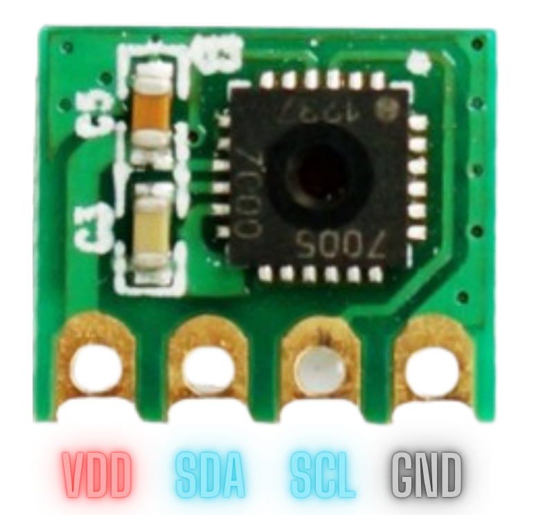
The TH02 is a compact, digital sensor designed to measure relative humidity and temperature with high precision. This monolithic CMOS sensor integrates sensing elements, signal processing, and calibration data into a single chip, facilitating straightforward I2C–based integration with microcontrollers. Its factory-calibrated design ensures ease of use without additional calibration efforts.
TH02 Features and Applications
Key Features:
- Dual Sensing Capabilities: Measures both temperature and relative humidity.
- Factory Calibration: Includes on-chip calibration data for plug-and-play integration.
- High Accuracy: ±0.5°C for temperature and ±4.5% RH across its operational range.
- Low Power Consumption: Ideal for battery-powered and embedded applications.
- Wide Operational Range: 0–100% RH and -40°C to +85°C.
- I2C Interface: Supports data rates up to 400 kHz for rapid communication.
- Integrated Heater: Helps manage condensation and stabilize readings in high humidity.
Applications:
- HVAC Systems: Efficient climate control and monitoring.
- Automotive: Cabin humidity and temperature regulation.
- Industrial Monitoring: Precision tracking in controlled environments.
- Consumer Electronics: Portable weather stations and smart home systems.
TH02 Block Diagram
The TH02 sensor integrates advanced features for precise environmental monitoring in a compact 4×4 mm QFN package. It combines reliable sensing, efficient data processing, and seamless microcontroller integration for embedded systems.
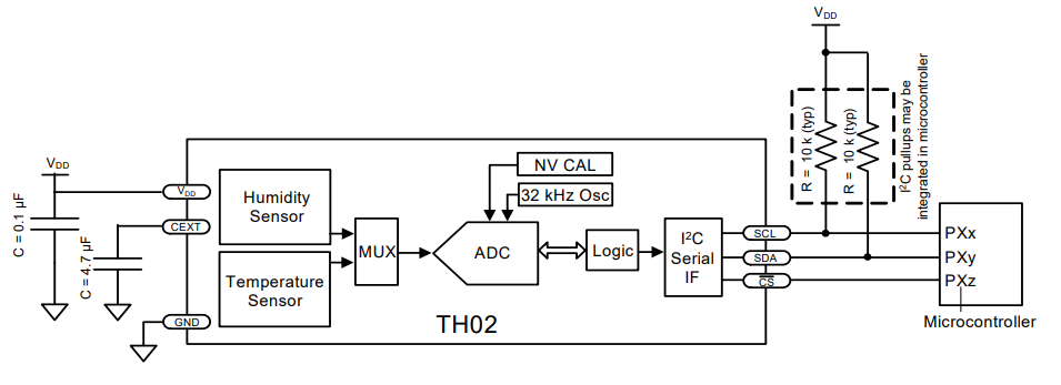
- Includes humidity and temperature sensors using capacitive polymer and thermal elements.
- Features an ADC with multiplexer for accurate digital signal conversion.
- Utilizes non-volatile memory for factory-calibrated coefficients.
- Equipped with a 32 kHz oscillator and I2C host interface for precise timing and communication.
Relative Humidity Sensor Accuracy and Compensation Techniques
Accuracy Measurement
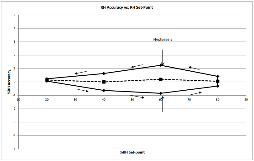
The TH02 sensor’s accuracy is evaluated in a controlled temperature and humidity chamber, typically at 30°C. Humidity is cycled between 20% and 80% in defined increments, with measurements taken after a 30-minute stabilization at each set-point. The accuracy is determined by averaging readings across these cycles, yielding a typical accuracy of ±0.25% RH after linearization.
actors Affecting Accuracy
- Included in Specifications: Factory calibration accuracy, unit-to-unit variations, and compensation for solder reflow shifts.
- Excluded from Specifications: Hysteresis (±1%), long-term drift, contamination, and temperature effects (compensated separately).
Linearization
The TH02 applies a second-order polynomial to correct non-linearities in relative humidity readings. Coefficients (A0, A1, A2) are factory-characterized to ensure accurate linearized outputs.
Temperature Compensation
As the sensor is calibrated at 30°C, readings at other temperatures require compensation. A formula using temperature coefficients (Q0, Q1) adjusts the RHLinear value to maintain accuracy, particularly effective in the 15–50°C range.
Hysteresis and Exposure Effects
- Hysteresis: A memory effect causes minor offsets in readings after exposure to high or low humidity. Typical uncertainty from hysteresis is ±1.05% RH.
- Prolonged High Humidity: Long exposure to high humidity can cause upward drift in readings. This drift can be reversed using a bake-and-hydrate procedure for sensor recovery.
Project : Interfacing TH02 Sensor with PIC16F877A for Temperature and Humidity Monitoring
This project demonstrates interfacing the TH02 I2C temperature and humidity sensor with the PIC16F877A microcontroller. The system continuously measures environmental conditions, processes raw and compensated values, and transmits data via UART. The implementation ensures real-time and reliable environmental monitoring for embedded applications.
I2C Driver Header File (i2c.h)
This file contains the core functions for I2C communication between the PIC16F877A microcontroller and the TH02 sensor.
#ifndef I2C_H
#define I2C_H

#include <xc.h>
#include <stdlib.h>
#include <stdint.h>
#include"stdio.h"

#define _XTAL_FREQ             16000000
#define I2C_BaudRate           100000
#define SCL_D                  TRISC3
#define SDA_D                  TRISC4

// Function prototypes
void I2C_Master_Init(void);
void I2C_Master_Wait(void);
void I2C_Master_Start(void);
void I2C_Master_RepeatedStart(void);
void I2C_Master_Stop(void);
void I2C_ACK(void);
void I2C_NACK(void);
unsigned char I2C_Master_Write(unsigned char data);
unsigned char I2C_Read_Byte(void);

#endif
UART Driver Header File (uart.h)
This file defines UART functions for transmitting data from the PIC16F877A to a connected Terminal.
#ifndef UART_H
#define UART_H

#include "i2c.h"

void UART_TX_Init(void);
uint8_t UART_TX_Empty(void);
void UART_Write(uint8_t data);
void UART_Write_Text(const char* text);

#endif
TH02 Sensor Driver Header File (TH02.h)
The TH02 driver provides functions to configure the sensor, perform conversions, and retrieve data.
#ifndef TH02_H
#define TH02_H

#include "i2c.h"

#define TH02_I2C_ADDR 0x40
#define TH02_STATUS 0
#define TH02_DATAh  1
#define TH02_DATAl  2
#define TH02_CONFIG 3

// Function prototypes
uint8_t TH02_WriteRegister(uint8_t reg, uint8_t value);
uint8_t TH02_ReadRegister(uint8_t reg, uint8_t *value);
uint8_t TH02_StartTempConversion(uint8_t fastmode, uint8_t heater);
uint8_t TH02_StartRHConversion(uint8_t fastmode, uint8_t heater);
uint8_t TH02_WaitForReady(void);
int16_t TH02_GetConversionValue(void);
int16_t TH02_GetCompensatedRH(uint8_t round_flag);

#endif
Main Application File (main.c)
The main application integrates the TH02 sensor with the microcontroller, initializing peripherals, managing conversions, and formatting output for UART transmission.
#include <xc.h>
#include "i2c.h"
#include "uart.h"
#include "TH02.h"
#include <stdio.h>

void main(void) {
    char displayText[64];
    int16_t tempRaw, humRaw, humComp;

    // Initialize I2C and UART
    I2C_Master_Init();
    UART_TX_Init();
    UART_Write_Text("TH02 Sensor Initialization\n\r");

    while (1) {
        // Start Temperature Conversion
        TH02_StartTempConversion(0, 0);
        if (TH02_WaitForReady() == 0) {
            tempRaw = TH02_GetConversionValue();
        } else {
            tempRaw = TH02_UNDEFINED_VALUE;
        }

        // Start Humidity Conversion
        TH02_StartRHConversion(0, 0);
        if (TH02_WaitForReady() == 0) {
            humRaw  = TH02_GetConversionValue();
            humComp = TH02_GetCompensatedRH(1);
        } else {
            humRaw = TH02_UNDEFINED_VALUE;
            humComp = TH02_UNDEFINED_VALUE;
        }

        // Send Data via UART
        snprintf(displayText, sizeof(displayText), "Temperature: %d.%01d C\n\r", tempRaw / 10, abs(tempRaw % 10));
        UART_Write_Text(displayText);

        snprintf(displayText, sizeof(displayText), "Humidity (Raw): %d.%01d %%\n\r", humRaw / 10, abs(humRaw % 10));
        UART_Write_Text(displayText);

        snprintf(displayText, sizeof(displayText), "Humidity (Compensated): %d.%01d %%\n\r", humComp / 10, abs(humComp % 10));
        UART_Write_Text(displayText);

        UART_Write_Text("Waiting 10 seconds for next measurement...\n\r");
        __delay_ms(10000); // 10 seconds
    }
}
Proteus Configuration :
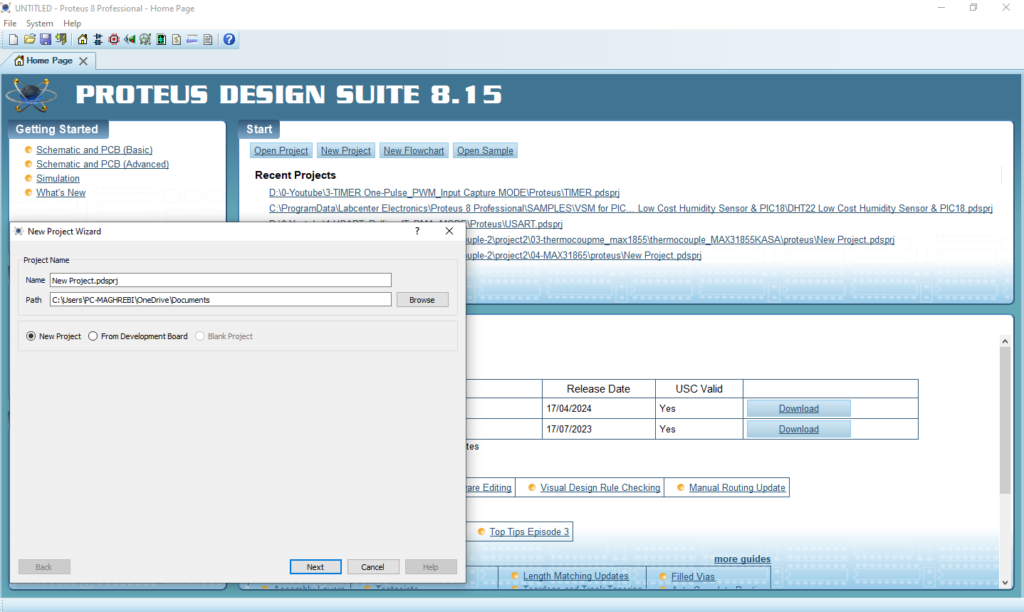
- Open Proteus & Create New Project and click next
- Click on Pick Device
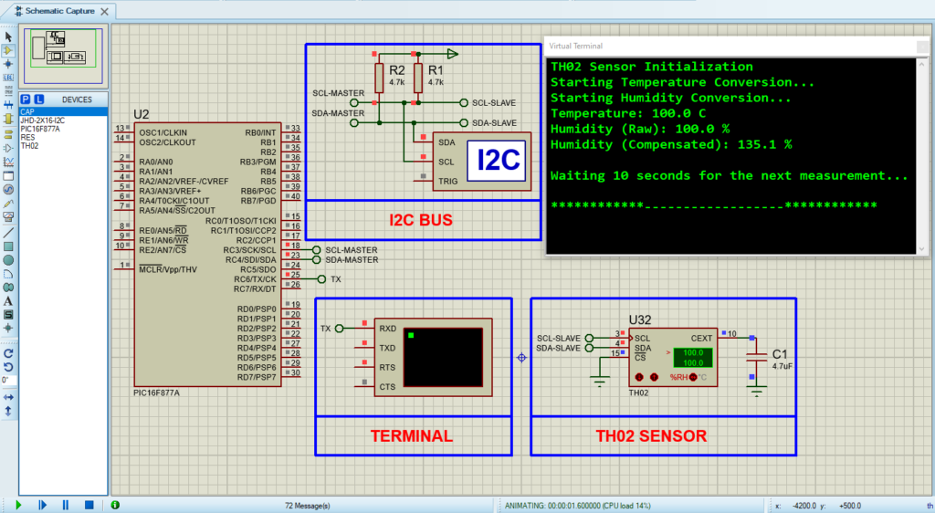
- Search for PIC16F877A & TH02 & RESISTOR & CAPACITOR
- Click on Virtual Instruments Mode then choose I2C DEBUGGER

- Click on Terminal Mode then choose (DEFAULT & POWER &GROUND)
- finally make the circuit below and start the simulation
That’s all!
If you have any questions or suggestions don’t hesitate to leave a comment below
