In this article, we explore how to integrate the TC72 Temperature Sensor with the PIC16F877A microcontroller for efficient temperature monitoring and control.
TC72 Temperature Sensor: Interfacing with PIC Microcontroller for Accurate Temperature Monitoring
In this project, we will explore the integration of the TC72 temperature sensor with the PIC16F877A microcontroller using the SPI (Serial Peripheral Interface) protocol. This setup demonstrates how to create a robust and efficient temperature monitoring system, enabling precise temperature measurement, real-time data logging, and seamless communication between the sensor and microcontroller.
TC72 Overview
The TC72 is a highly efficient digital temperature sensor designed to provide accurate temperature readings across a wide range of applications. This sensor is capable of measuring temperatures from -55°C to +125°C, making it suitable for both extreme and moderate environments. The TC72 integrates a temperature-to-digital converter and features an SPI-compatible interface, allowing seamless communication with microcontrollers and other digital systems. Its compact design and low power consumption make it an ideal choice for modern electronic devices where space and energy efficiency are critical.
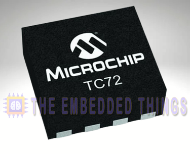
TC72 Features and Applications
Key Features
- High Accuracy: The TC72 offers ±2°C accuracy from -40°C to +85°C and ±3°C accuracy from -55°C to +125°C, ensuring reliable temperature measurements in various conditions.
- 10-Bit Resolution: With a resolution of 0.25°C per bit, the TC72 provides precise temperature readings, making it suitable for applications requiring fine temperature control.
- Low Power Consumption: The sensor consumes only 250 µA in Continuous Temperature Conversion mode and as little as 1 µA in Shutdown mode, making it ideal for battery-powered devices.
- SPI-Compatible Interface: The TC72’s serial interface is fully compatible with the SPI protocol, enabling easy integration with microcontrollers and other digital systems.
- Flexible Operating Modes: The sensor supports both Continuous Conversion mode, which measures temperature every 150 ms, and One-Shot mode, which performs a single measurement before returning to a low-power state.
Applications
The TC72 is versatile and can be used in a wide range of applications, including:
- Personal Computers and Servers: For thermal management and overheating protection.
- Hard Disk Drives and PC Peripherals: To monitor and control temperature in storage devices.
- Entertainment Systems: Ensuring optimal performance by maintaining safe operating temperatures.
- Office Equipment: Such as printers and copiers, where temperature monitoring is crucial.
- Datacom Equipment: For maintaining stable temperatures in networking hardware.
- Mobile Phones: To prevent overheating and ensure device longevity.
- General Purpose Temperature Monitoring: In various industrial and consumer electronics.
TC72 Block Diagram
The TC72’s internal architecture is designed for efficient temperature sensing and data conversion. Below is a simplified block diagram of the TC72:
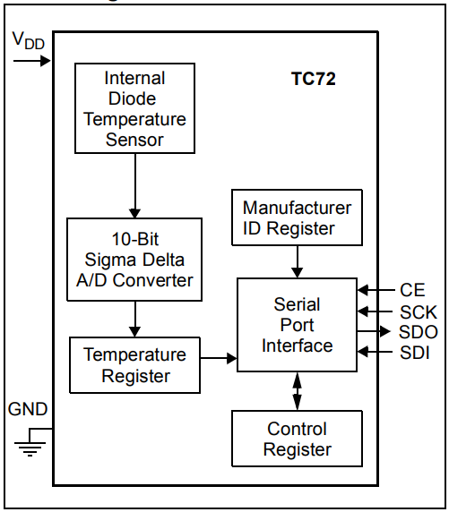
Key Components:
- Internal Diode Temperature Sensor: Measures the temperature and converts it into an analog signal.
- 10-Bit Sigma Delta A/D Converter: Converts the analog signal from the temperature sensor into a digital format with high precision.
- Temperature Register: Stores the digital temperature data for retrieval via the serial interface.
- Control Register: Manages the operational modes of the TC72, including Continuous Conversion and Shutdown modes.
- Serial Port Interface: Facilitates communication with external devices using the SPI protocol.
TC72 Power Management and Operational Modes
The TC72 defaults to Shutdown mode on power-up, consuming only 1 µA, making it ideal for low-power applications. It can be switched to Continuous Conversion mode for regular temperature measurements or One-Shot mode for single readings. Ensure the supply voltage stays within 2.65V to 5.5V to avoid resetting internal registers.
Project: Interfacing TC72 Temperature Sensor with PIC Microcontroller
This project demonstrates how to interface the TC72 digital temperature sensor with a PIC microcontroller using the SPI protocol. The system reads temperature data from the TC72 and transmits it over UART for monitoring. The project also showcases the TC72’s operational modes, including Continuous Conversion, One-Shot, and Shutdown modes, to optimize power consumption. Below is a detailed explanation of the code files used in the project:
Main Header File (main.h)
This header file defines the configuration bits for the PIC microcontroller, sets the oscillator frequency, and includes necessary libraries.
#ifndef MAIN_H
#define MAIN_H

#include <xc.h>
#include <stdint.h>
#include <stdio.h>
#include <stdbool.h>

// Configuration Bits
#pragma config FOSC = XT       // Oscillator Selection bits (XT oscillator)
#pragma config WDTE = OFF      // Watchdog Timer Enable bit (WDT disabled)
#pragma config PWRTE = OFF     // Power-up Timer Enable bit (PWRT disabled)
#pragma config BOREN = ON      // Brown-out Reset Enable bit (BOR enabled)
#pragma config LVP = OFF       // Low-Voltage Programming Disable
#pragma config CPD = OFF       // Data EEPROM Memory Code Protection bit (Data EEPROM code protection off)
#pragma config WRT = OFF       // Flash Program Memory Write Enable bits (Write protection off)
#pragma config CP = OFF        // Flash Program Memory Code Protection bit (Code protection off)

#define _XTAL_FREQ 16000000  // Oscillator Frequency (16MHz)

#endif /* MAIN_H */
UART Header File (uart.h)
This header file defines the UART functions for initializing and handling serial communication between the PIC microcontroller and an external device (e.g., a PC or another microcontroller).
#ifndef UART_H
#define UART_H
#include "main.h"

// Function prototypes
void UART_TX_Init(void);              // Initialize UART for transmission
uint8_t UART_TX_Empty(void);          // Check if UART transmit buffer is empty
void UART_Write(uint8_t data);        // Write a single byte to UART
void UART_Write_Text(const char* text); // Write a string to UART

#endif // UART_H
SPI Header File (spi.h)
This header file defines the constants, pin configurations, and function prototypes for the SPI communication protocol. It is used to interface with the TC72 temperature sensor.
#ifndef SPI_H
#define SPI_H

#include "main.h"

// Define the CS pin
#define CS_TRIS TRISCbits.TRISC2  // Configure RC2 direction
#define CS_PIN PORTCbits.RC2      // Access RC2 pin directly

// Function prototypes
void SPI_Master_Init();           // Initialize SPI in Master mode
void SPI_Set_CS(bool state);      // Control the Chip Select (CS) pin
void SPI_Write(uint8_t Data);     // Write a byte to SPI
uint8_t SPI_Read();               // Read a byte from SPI

#endif // SPI_H
TC72 Header File (tc72.h)
This header file defines the TC72 temperature sensor’s register addresses, operational modes, and function prototypes for initializing and reading temperature data.
#ifndef TC72_H
#define TC72_H

#include "spi.h"

// TC72 Register Definitions
#define CONTROL_REG       0x80  // Control Register (write access)
#define TEMPR_REG         0x02  // Temperature MSB Register
#define TEMP_LSB_REG      0x01  // Temperature LSB Register
#define MANUFACTURER_REG  0x03  // Manufacturer ID Register

// TC72 Mode Definitions
#define TC72_MODE_CONTINUOUS 0x00  // Continuous Mode
#define TC72_MODE_ONE_SHOT   0x10  // One-Shot Mode
#define TC72_MODE_SHUTDOWN   0x01  // Shutdown Mode

// Function prototypes
void TC72_SetMode(uint8_t mode);    // Configure the TC72's operational mode
float TC72_ReadTemperature();       // Read the temperature as a float
uint8_t TC72_ReadManufacturerID();  // Read the Manufacturer ID for verification

#endif // TC72_H
Main Source File (main.c)
This file contains the main logic for reading temperature data from the TC72 sensor and transmitting it over UART. It initializes the UART and SPI interfaces, verifies the TC72’s manufacturer ID, and demonstrates the sensor’s operational modes.
#include "main.h"
#include "uart.h"
#include "spi.h"
#include "tc72.h"

void main(void) {
    // Initialize UART and SPI
    UART_TX_Init();
    SPI_Master_Init();

    // Verify Manufacturer ID
    uint8_t manufacturerID = TC72_ReadManufacturerID();
    UART_Write_Text("Manufacturer ID: 0x");
    char buffer[5];
    sprintf(buffer, "%02X", manufacturerID);
    UART_Write_Text(buffer);
    UART_Write_Text("\n\r");

    if (manufacturerID != 0x54) {
        UART_Write_Text("Error: Incorrect Manufacturer ID\n\r");
        while (1); // Halt the program if the sensor is not detected
    }

    // Initialize TC72 in Continuous Mode
    TC72_SetMode(TC72_MODE_CONTINUOUS);
    UART_Write_Text("TC72 Initialized in Continuous Mode\n\r");

    while (1) {
        // Read temperature
        float temperature = TC72_ReadTemperature();

        // Print temperature
        UART_Write_Text("Temperature: ");
        sprintf(buffer, "%.2f C", temperature);
        UART_Write_Text(buffer);
        UART_Write_Text("\n\r");

        // Simulate low-power use case by switching to One-Shot Mode
        __delay_ms(1000); // Wait for 1 second
        UART_Write_Text("Switching to One-Shot Mode...\n\r");
        TC72_SetMode(TC72_MODE_ONE_SHOT);
        __delay_ms(150); // Wait for single conversion
        temperature = TC72_ReadTemperature();
        UART_Write_Text("One-Shot Temperature: ");
        sprintf(buffer, "%.2f C", temperature);
        UART_Write_Text(buffer);
        UART_Write_Text("\n\r");

        // Switch back to Shutdown Mode to save power
        UART_Write_Text("Switching to Shutdown Mode...\n\r");
        TC72_SetMode(TC72_MODE_SHUTDOWN);
        __delay_ms(1000); // Simulate idle time
    }
}
Proteus Configuration :
- Open Proteus & Create New Project and click next
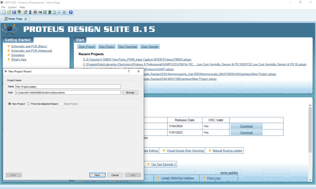
- Click on Pick Device
- Search for PIC16F877A & TC72 & NOT
- Click on Virtual Instruments Mode then choose TERMINAL
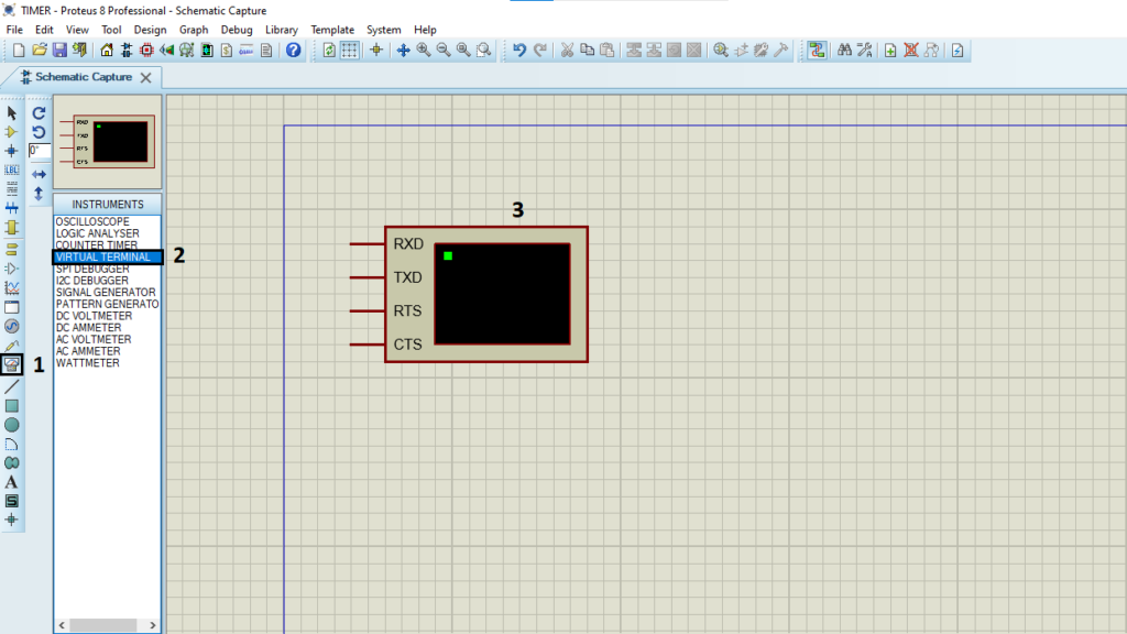
- Click on Terminal Mode then choose (DEFAULT & POWER &GROUND)
- finally make the circuit below and start the simulation
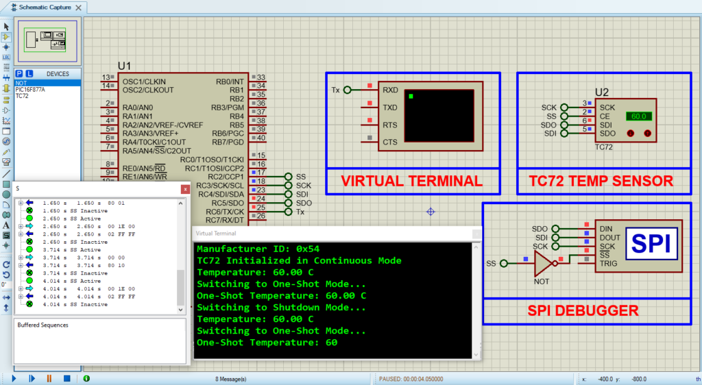
That’s all!
If you have any questions or suggestions don’t hesitate to leave a comment below
