In this article, we explain how to implement PIC16F877A stepper motor control using the ULN2003 driver, complete with practical examples.
Interfacing PIC16F877 with L298 Motor Driver and ULN2003 for Stepper Motor Control
In this project, we will explore how to interface the PIC16F877A microcontroller with the ULN2003 driver to control a stepper motor, providing precise motion control ideal for robotics and automation applications. For additional insights, check out a related project: “Driving a Stepper Motor with the ULN2003 Motor Driver and STM32.”
Overview of the ULN2003
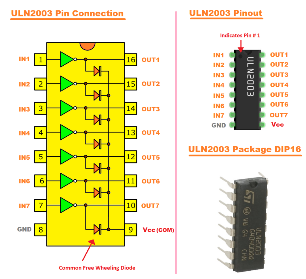
The ULN2003 is a versatile motor driver IC comprising seven NPN Darlington transistor pairs, each capable of handling up to 500 mA and 50 V. This configuration allows it to interface low-power logic circuits, such as those from microcontrollers, with higher power loads like motors and relays. Integrated flyback diodes provide protection against voltage spikes from inductive loads, enhancing the IC’s reliability in various applications.
ULN2003 and Stepper Motor Control
When controlling stepper motors, the ULN2003 serves as an effective interface between a microcontroller and the motor. For instance, the 28BYJ-48 stepper motor can be driven using the ULN2003 driver board, which simplifies connections and includes indicator LEDs to display the stepping state. This setup enables precise control over motor movements, making it suitable for applications requiring accurate positioning, such as in robotics and automation systems.

Project: Stepper Motor Control with PIC16F877A and UART Commands
This project demonstrates how to control a stepper motor using the PIC16F877A microcontroller. The setup enables forward, backward, and stop commands via UART communication. Using a predefined step sequence and UART commands, this system showcases precise control of the stepper motor, suitable for applications requiring accurate motion such as robotics and automation.
Configuration and Definitions
This section describes the microcontroller’s configuration, including UART initialization for communication and setting up pins for stepper motor control.
#include <xc.h>
#include <stdint.h>

// Configuration bits
#pragma config FOSC = XT        // Oscillator Selection bits
#pragma config WDTE = OFF       // Watchdog Timer Enable bit
#pragma config PWRTE = ON       // Power-up Timer Enable bit
#pragma config BOREN = ON       // Brown-out Reset Enable bit
#pragma config LVP = OFF        // Low-Voltage (Single-Supply) In-Circuit Serial Programming Enable bit
#pragma config CPD = OFF        // Data EEPROM Memory Code Protection bit
#pragma config WRT = OFF        // Flash Program Memory Write Enable bits
#pragma config CP = OFF         // Flash Program Memory Code Protection bit

#define _XTAL_FREQ 8000000      // Define crystal frequency for delay
#define out PORTD               // Stepper motor connected to PORTD

// Turn sequence for stepper motor
const unsigned char turn[] = {0x02, 0x06, 0x04, 0x0C, 0x08, 0x09, 0x01, 0x03};
UART Setup and Communication Functions
The UART is configured to allow the microcontroller to communicate commands via a serial terminal. This enables real-time control over the stepper motor’s direction and state.
void UART_TX_Init(void)
{
    // Set baud rate to 9600 bps
    BRGH = 1;       // High-speed baud rate
    SPBRG = 51;     // Set SPBRG for 9600 bps with 8 MHz clock

    // Enable Asynchronous Serial Port
    SYNC = 0;
    SPEN = 1;

    // Set RX-TX Pins to be in UART mode
    TRISC6 = 0;     // TX pin (output)
    TRISC7 = 1;     // RX pin (input)

    // Enable UART Transmission
    TXEN = 1;
    // Enable UART Reception
    CREN = 1;
}

void UART_Write_Text(const char* text)
{
    while (*text != '\0') {
        UART_Write(*text++);
    }
}
Stepper Motor Control Logic
The motor’s control logic uses UART commands to switch between forward, backward, and stop states. A predefined sequence of steps is applied to the motor for precise control.
void main(void) {
    unsigned char i = 0;

    // Configure Ports
    TRISD = 0x00;              // Set PORTD as output
    PORTD = 0xFF;              // Initialize PORTD to high
    UART_TX_Init();            // Initialize UART
    char command = 'S';        // Default state is stopped
    out = 0x00;                // Stop motor
    UART_Write_Text("Stepper Motor Control Initialized\n\r");
    UART_Write_Text("Enter 'F' to move forward, 'B' to move backward, or 'S' to stop:\n\r");

    while (1) {
        // Check if a new command is received
        if (PIR1bits.RCIF) {
            char new_command = UART_Read();  // Read the new command

            if (new_command == 'F' || new_command == 'f') {
                UART_Write_Text("\n\rMotor Moving Forward\n\r");
                command = 'F';  // Update the state to forward
            } else if (new_command == 'B' || new_command == 'b') {
                UART_Write_Text("\n\rMotor Moving Backward\n\r");
                command = 'B';  // Update the state to backward
            } else if (new_command == 'S' || new_command == 's') {
                UART_Write_Text("\n\rMotor Stopped\n\r");
                command = 'S';  // Update the state to stopped
            } else {
                UART_Write_Text("\n\rInvalid Command. Maintaining Last State.\n\r");
                // Keep the current command unchanged
            }
        }

        // Act based on the current valid command
        if (command == 'F') {
            i = (i < 7) ? i + 1 : 0;  // Increment index with wraparound
            out = turn[i];           // Output step sequence
            __delay_ms(50);          // Step delay
        } else if (command == 'B') {
            i = (i > 0) ? i - 1 : 7;  // Decrement index with wraparound
            out = turn[i];           // Output step sequence
            __delay_ms(50);          // Step delay
        } else if (command == 'S') {
            out = 0x00;              // Stop motor
        }
    }
}
Proteus Configuration :
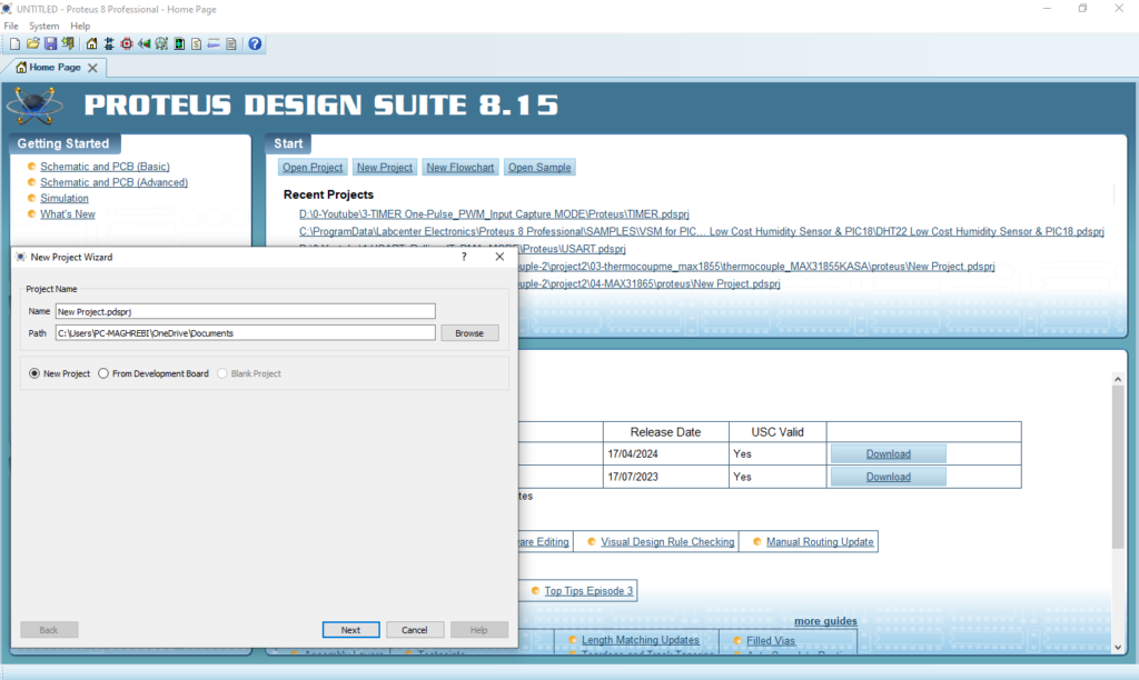
- Open Proteus & Create New Project and click next
- Click on Pick Device
- Search for PIC16F877A & ULN2003A & MOTOR-BISTEPPER & RES & LED-GREEN
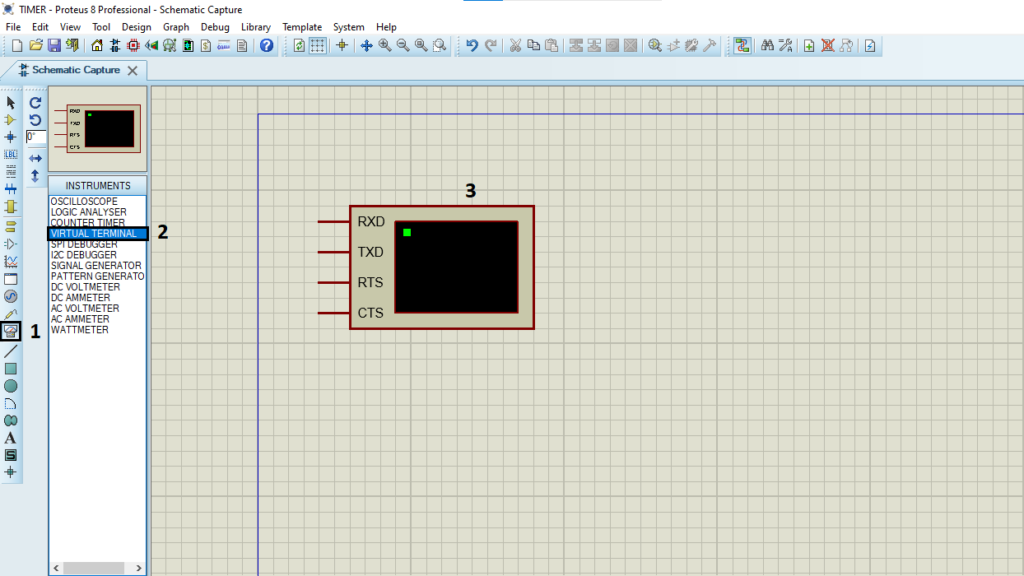
- Click on Virtual Instrumets Mode then choose VIRTUAL TERMINAL
- Click on Terminal Mode then choose (DEFAULT & POWER & GROUND)
- finally make the circuit below and start the simulation
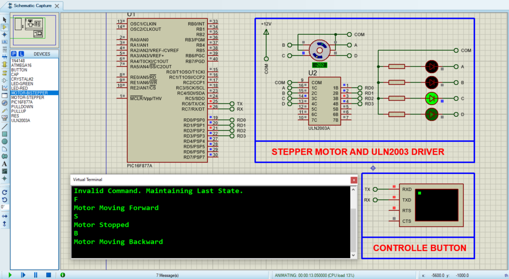
That’s all!
If you have any questions or suggestions don’t hesitate to leave a comment below
