In this article, we explore PIC16F877A Servo Motor Control, detailing its setup, programming, and techniques for achieving precise motion control.

Interfacing PIC16F877A with Servo Motors for Precise Control
In this project, we will explore how to interface the PIC16F877A microcontroller with a servo motor to achieve precise position control, making it ideal for robotics and automation systems. For additional insights, check out a related project: “Controlling Servo Motors with STM32 Microcontrollers.”
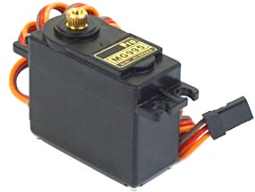
Understanding Servo Motors
Servo motors are specialized devices that provide precise angular motion, typically within a 0° to 180° range. They consist of a DC motor, gearbox, and a feedback system, allowing for accurate control over position and speed. This precision makes them ideal for applications in robotics, automation, and control systems.
Interfacing PIC16F877A with a Servo Motor
To control a servo motor using the PIC16F877A microcontroller, a Pulse Width Modulation (PWM) signal is employed. The servo motor interprets the width of these pulses to determine its angular position. For instance, a 1 ms pulse might correspond to a 0° position, while a 2 ms pulse corresponds to 180°. By configuring the PIC16F877A to generate PWM signals with varying pulse widths, precise control over the servo motor’s position is achieved
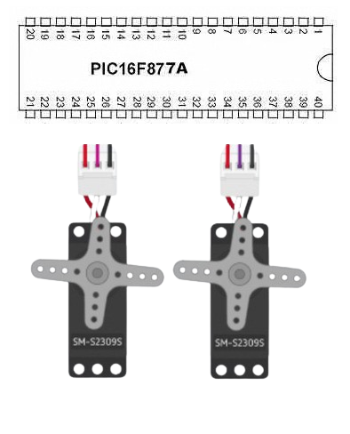
Project: Servo Motor Control with PIC16F877A Microcontroller
This project demonstrates how to control a servo motor using the PIC16F877A microcontroller by generating precise PWM signals. The servo motor’s position can be varied based on ADC readings, making it suitable for automation and robotics requiring precise angular control.
Configuration and Definitions
This section includes microcontroller configurations and setup for PWM generation to control the servo motor.
#include "main.h"
#include "adc.h"
#include "lcd.h"

// Servo Control Definitions
#define MIN_PULSE_WIDTH       109   // Minimum pulse width (in timer ticks)
#define MAX_PULSE_WIDTH       221   // Maximum pulse width (in timer ticks)
#define DEFAULT_PULSE_WIDTH   165   // Default pulse width (in timer ticks)
#define TIMER1_RELOAD_VALUE   5000  // Reload value for 20 ms frame (4 MHz clock, 1:8 prescaler)

// Servo Structure
typedef struct {
    uint8_t pin;           // Pin number
    uint16_t pulseWidth;   // Pulse width in timer ticks
} Servo;

// Global Variables
static Servo servo;
Timer1 Setup and ISR
Timer1 is configured for generating the periodic PWM signal required by the servo motor. The ISR toggles the servo’s pin to create the pulse.
// Timer1 Interrupt Service Routine
void __interrupt() ISR(void) {
    if (TMR1IF) {
        TMR1IF = 0;  // Clear Timer1 interrupt flag
        updateServoPulse();

        // Reload Timer1 for the next 20 ms frame
        TMR1H = TIMER1_RELOAD_VALUE >> 8;
        TMR1L = TIMER1_RELOAD_VALUE & 0xFF;
    }
}
Servo Initialization and Update Functions
Functions for initializing and updating the servo’s pulse width based on ADC readings.
// Setup Servo on a Specific Pin with a Default Pulse Width
void setupServo(uint8_t pin, uint16_t defaultPulseWidth) {
    servo.pin = pin;  // Assign pin
    servo.pulseWidth = defaultPulseWidth;  // Set default pulse width
    TRISE &= ~(1 << servo.pin);  // Set pin as output
    PORTE &= ~(1 << servo.pin);  // Initialize pin to LOW
    initTimer1();  // Initialize Timer1
}

// Update the Servo Pulse (called in ISR)
void updateServoPulse(void) {
    PORTE |= (1 << servo.pin);  // Set pin HIGH
    for (uint16_t i = 0; i < servo.pulseWidth; i++) __asm("nop");  // Wait for pulse width
    PORTE &= ~(1 << servo.pin);  // Set pin LOW
}
Main Function Logic
The main function reads ADC values, calculates the corresponding pulse width and angle, and updates the servo motor.
void main(void) {
    uint16_t adcResult = 0;
    float voltage = 0.0;
    uint16_t pulseWidth = DEFAULT_PULSE_WIDTH;
    float angle = 0.0;

    // Initialize peripherals
    lcd_initialize();
    configure_ADC();
    setupServo(0, DEFAULT_PULSE_WIDTH);  // Initialize servo on RE0 with default pulse width

    while (1) {
        // Read ADC and calculate values
        start_ADC_conversion();
        wait_for_conversion();
        adcResult = read_ADC_result();

        // Calculate pulse width and angle
        calculatePulseWidthAndAngle(adcResult, &pulseWidth, &angle);

        // Update servo and display
        setServoPulseWidth(pulseWidth);
        displayReadings((adcResult * 5.0) / 1023.0, angle);

        __delay_ms(500);
    }
}
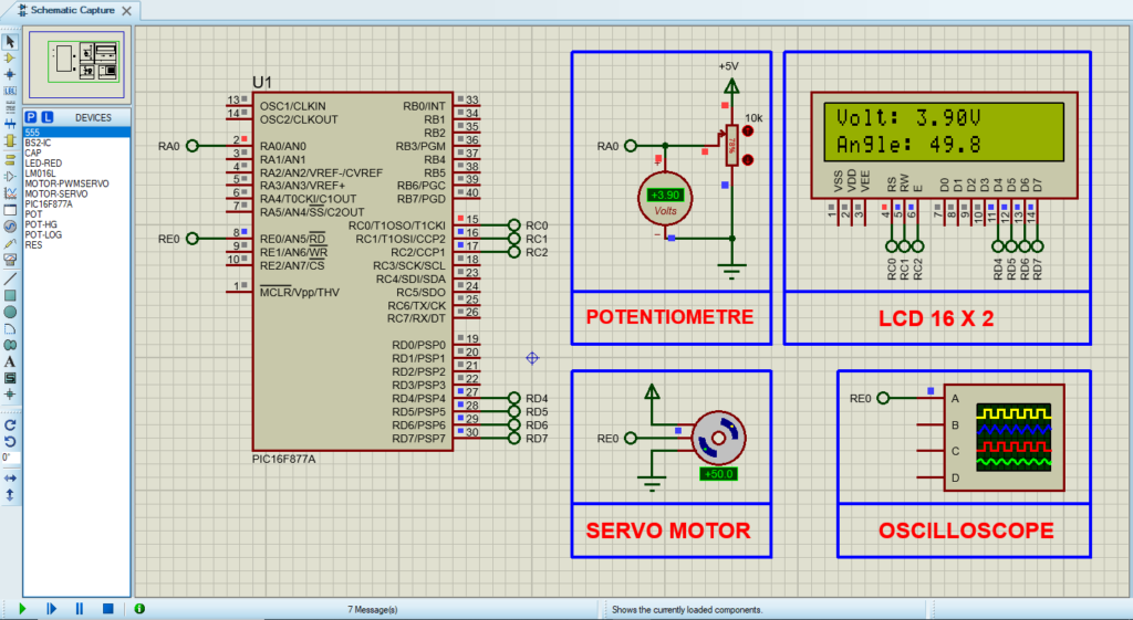
Proteus Configuration :
- Open Proteus & Create New Project and click next
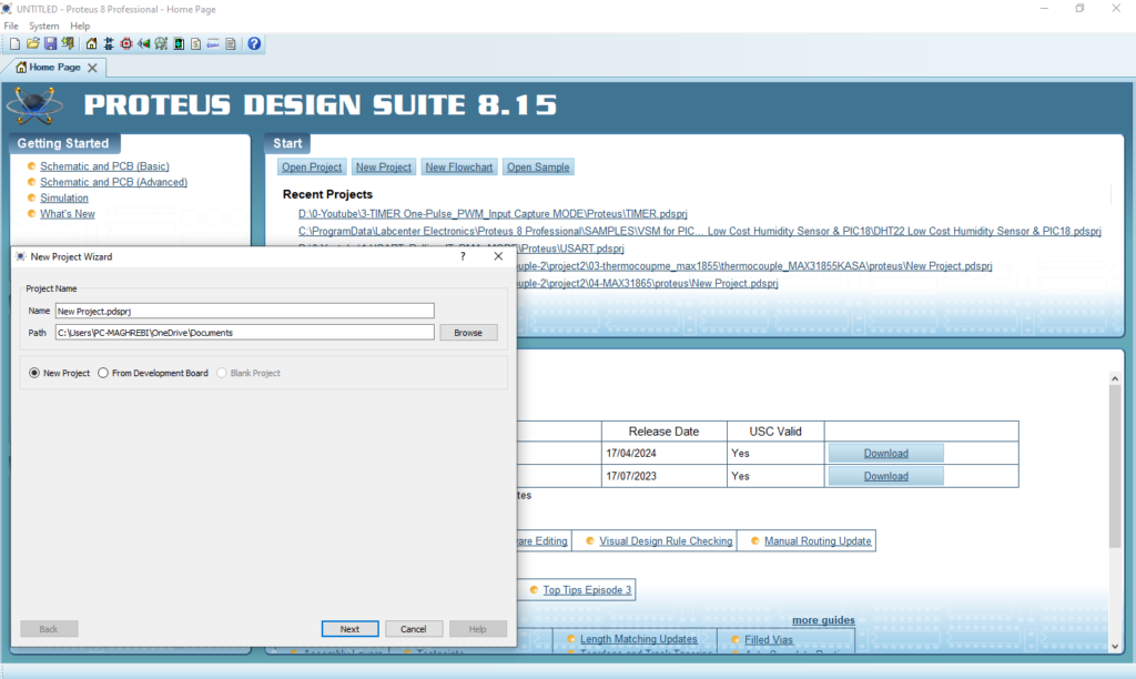
- Click on Pick Device
- Search for PIC16F877A & POT & MOTOR-PWMSERVO & LCD
- Click on Virtual Instrumets Mode then choose OSCILLOSCOPE
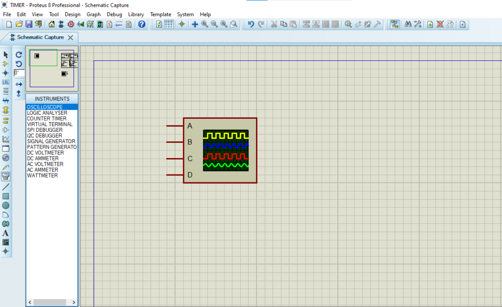
- Click on Terminal Mode then choose (DEFAULT & POWER & GROUND)
- finally make the circuit below and start the simulation
That’s all!
If you have any questions or suggestions don’t hesitate to leave a comment below

1 comment
[…] and precise motor control applications. This project builds upon my previous work, ‘PIC16F877A Servo Motor Control‘, where I demonstrated basic servo […]