In this article, learn how to build a Multi-Servo Motor Control System using the PCA9685 PWM driver and PIC16F877A microcontroller for precise robotics and automation applications.
Building a Multi-Servo Motor Control System with PCA9685 PWM Driver and Microcontroller
In this project, we will explore how to interface the PCA9685 PWM driver with the PIC16F877A microcontroller to create a Multi-Servo Motor Control System, perfect for robotics, automation, and precise motor control applications. This project builds upon my previous work, ‘PIC16F877A Servo Motor Control‘, where I demonstrated basic servo control.
PCA9685 Overview
The PCA9685 is a 16-channel, 12-bit PWM (Pulse Width Modulation) controller designed for precise control of LEDs, servos, and other devices requiring PWM signals. It communicates via the I²C bus, making it easy to integrate with microcontrollers like the PIC16F877A. Each of the 16 channels can independently control the brightness of LEDs or the position of servos with 12-bit resolution (4096 steps), allowing for smooth and accurate adjustments. The PCA9685 is widely used in applications such as robotics, lighting control, and automation due to its versatility and ease of use.
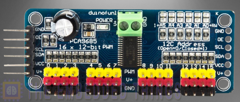
PCA9685 Features and Applications
Key Features:
- 16 Independent PWM Channels: Each channel can be individually controlled with 12-bit resolution.
- I²C Interface: Supports Fast-mode Plus (Fm+) I²C communication up to 1 MHz, enabling high-speed control.
- Adjustable PWM Frequency: The PWM frequency can be programmed from 24 Hz to 1526 Hz, making it suitable for a wide range of applications.
- High Drive Capability: Each output can sink up to 25 mA, allowing direct connection to LEDs or servos.
- Programmable Outputs: Outputs can be configured as open-drain or totem pole, providing flexibility for different applications.
- Low Power Consumption: Ideal for battery-powered devices and energy-efficient designs.
Applications:
- LED Dimming and Control: Perfect for RGB LED strips, backlighting, and decorative lighting.
- Servo Motor Control: Used in robotics and automation to control multiple servos with precision.
- Display Backlighting: Provides adjustable brightness control for LCD and OLED displays.
- Industrial Automation: Enables precise control of actuators and other PWM-driven devices.
PCA9685 Block Diagram
The PCA9685‘s internal architecture is designed for efficient PWM generation and control. Below is a simplified representation of its block diagram:
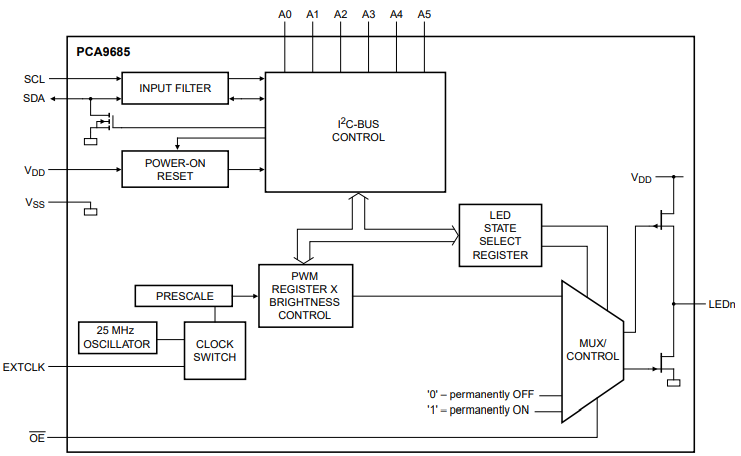
- I²C Interface: Handles communication with the microcontroller or host device.
- Control Logic: Manages the configuration and operation of the PWM channels.
- PWM Generators: Each of the 16 channels has its own 12-bit PWM generator for precise control.
- Output Drivers: Drive the PWM signals to the output pins, with configurable open-drain or totem pole options.
- Clock Source: Uses an internal 25 MHz oscillator or an external clock for synchronization.
- Power Management: Ensures efficient operation and supports low-power modes.
Why Choose the PCA9685?
The PCA9685 is a standout choice for PWM control due to its combination of high channel count, precision, and ease of use. Its ability to control up to 16 devices independently with 12-bit resolution makes it ideal for complex systems requiring fine-grained control. The I²C interface simplifies integration, while the adjustable PWM frequency ensures compatibility with a wide range of devices, from LEDs to servos.
One of the most compelling features of the PCA9685 is its staggered output capability, which minimizes current surges by allowing programmable on/off delays for each channel. This is particularly useful in applications like LED lighting, where sudden current spikes can cause flickering or damage. Additionally, the device’s software reset feature allows for easy reconfiguration and troubleshooting, making it a reliable choice for both prototyping and production.
For developers working on robotics, lighting systems, or automation projects, the PCA9685 offers a robust and flexible solution that simplifies design and enhances performance. Its combination of features, ease of integration, and reliability makes it a go-to component for PWM control in a variety of applications.
Project: Interfacing PCA9685 PWM Servo Driver with PIC Microcontroller
This project demonstrates how to interface the PCA9685 PWM Servo Driver with a PIC microcontroller using the I²C communication protocol. The system controls multiple servo motors by generating precise PWM signals, allowing for smooth and accurate movement. Below is a detailed explanation of the code files used in the project:
I2C Driver Header File (i2c.h)
This header file defines the I²C driver functions for initializing and handling I²C communication between the PIC microcontroller and the PCA9685 PWM Servo Driver.
#ifndef I2C_H
#define I2C_H

#include <xc.h>
#include <stdint.h>

// Define constants
#define _XTAL_FREQ             16000000
#define I2C_BaudRate           100000
#define SCL_D                  TRISC3
#define SDA_D                  TRISC4

// Function prototypes
void I2C_Master_Init(void);          // Initialize I2C in Master mode
void I2C_Master_Wait(void);          // Wait for I2C operation to complete
void I2C_Master_Start(void);         // Send I2C start condition
void I2C_Master_RepeatedStart(void); // Send I2C repeated start condition
void I2C_Master_Stop(void);          // Send I2C stop condition
void I2C_ACK(void);                  // Send I2C ACK
void I2C_NACK(void);                 // Send I2C NACK
unsigned char I2C_Master_Write(unsigned char data); // Write data to I2C bus
unsigned char I2C_Read_Byte(void);   // Read data from I2C bus

#endif
PCA9685 PWM Servo Driver Header File (PWMServoDriver.h)
This header file defines constants, configurations, and function prototypes for interacting with the PCA9685 PWM Servo Driver. It includes settings for PWM frequency, output modes, and servo control.
#ifndef _PWMSERVODRIVER_H
#define _PWMSERVODRIVER_H

#include "i2c.h"

// PCA9685 Register Addresses
#define PCA9685_MODE1 0x00
#define PCA9685_MODE2 0x01
#define PCA9685_SUBADR1 0x02
#define PCA9685_SUBADR2 0x03
#define PCA9685_SUBADR3 0x04
#define PCA9685_ALLCALLADR 0x05
#define PCA9685_LED0_ON_L 0x06
#define PCA9685_LED0_ON_H 0x07
#define PCA9685_LED0_OFF_L 0x08
#define PCA9685_LED0_OFF_H 0x09
#define PCA9685_ALLLED_ON_L 0xFA
#define PCA9685_ALLLED_ON_H 0xFB
#define PCA9685_ALLLED_OFF_L 0xFC
#define PCA9685_ALLLED_OFF_H 0xFD
#define PCA9685_PRESCALE 0xFE
#define PCA9685_TESTMODE 0xFF

// Mode1 Register Bits
#define MODE1_ALLCAL 0x01
#define MODE1_SUB3 0x02
#define MODE1_SUB2 0x04
#define MODE1_SUB1 0x08
#define MODE1_SLEEP 0x10
#define MODE1_AI 0x20
#define MODE1_EXTCLK 0x40
#define MODE1_RESTART 0x80

// Mode2 Register Bits
#define MODE2_OUTNE_0 0x01
#define MODE2_OUTNE_1 0x02
#define MODE2_OUTDRV 0x04
#define MODE2_OCH 0x08
#define MODE2_INVRT 0x10

// PCA9685 Default I2C Address
#define PCA9685_I2C_ADDRESS 0x40

// Function prototypes
void PWMServoDriver_Init(uint8_t addr, uint8_t prescale); // Initialize PCA9685
void PWMServoDriver_Reset(void);                         // Reset PCA9685
void PWMServoDriver_Sleep(void);                         // Put PCA9685 in sleep mode
void PWMServoDriver_Wakeup(void);                        // Wake up PCA9685
void PWMServoDriver_SetPWMFreq(float freq);              // Set PWM frequency
void PWMServoDriver_SetPWM(uint8_t num, uint16_t on, uint16_t off); // Set PWM for a specific channel
void PWMServoDriver_SetPin(uint8_t num, uint16_t val, uint8_t invert); // Set a specific pin
void PWMServoDriver_WriteMicroseconds(uint8_t num, uint16_t microseconds); // Set PWM in microseconds

#endif /* _PWMSERVODRIVER_H */
Main Application File (main.c)
This file initializes the hardware, sets up the PCA9685 PWM Servo Driver, and controls multiple servo motors by generating PWM signals. The servos move smoothly between their minimum and maximum positions.
#include "i2c.h"
#include "PWMServoDriver.h"

// Define servo pulse width boundaries
#define SERVOMIN  150 // Minimum pulse length count (out of 4096)
#define SERVOMAX  600 // Maximum pulse length count (out of 4096)

// Servo number counter
uint8_t servonum = 0;

void setServoPulse(uint8_t n, double pulse) {
    double pulselength;

    pulselength = 1000000;  // 1,000,000 us per second
    pulselength /= 60;      // 60 Hz
    pulselength /= 4096;    // 12 bits of resolution

    pulse *= 1000;          // Convert seconds to microseconds
    pulse /= pulselength;   // Convert microseconds to pulse width count

    PWMServoDriver_SetPWM(n, 0, (uint16_t)pulse);
}

int main(void) {
    // Initialize I2C and PWM Servo Driver
    I2C_Master_Init();
    PWMServoDriver_Init(PCA9685_I2C_ADDRESS, 0); // Default I2C address 0x40

    PWMServoDriver_SetPWMFreq(60); // Set frequency to ~60 Hz

    while (1) {
        // Drive each servo one at a time
        for (uint16_t pulselen = SERVOMIN; pulselen < SERVOMAX; pulselen++) {
            PWMServoDriver_SetPWM(servonum, 0, pulselen);
        }
        __delay_ms(500);

        for (uint16_t pulselen = SERVOMAX; pulselen > SERVOMIN; pulselen--) {
            PWMServoDriver_SetPWM(servonum, 0, pulselen);
        }
        __delay_ms(500);

        // Move to the next servo
        servonum++;
        if (servonum > 4) {
            servonum = 0;
        }
    }

    return 0;
}
Proteus Configuration :
- Open Proteus & Create New Project and click next
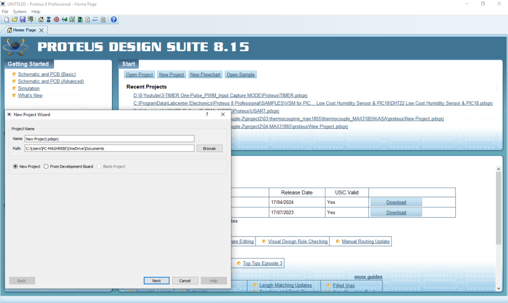
- Click on Pick Device
- Search for PIC16F877A & PCA9685 & 4 SERVO MOTORS & RESISTOR
- Click on Virtual Instruments Mode then choose OSCILLOSCOPE
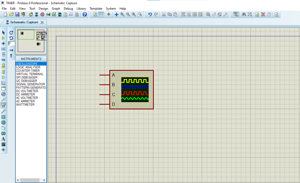
- Click on Terminal Mode then choose (DEFAULT & POWER &GROUND)
- finally make the circuit below and start the simulation
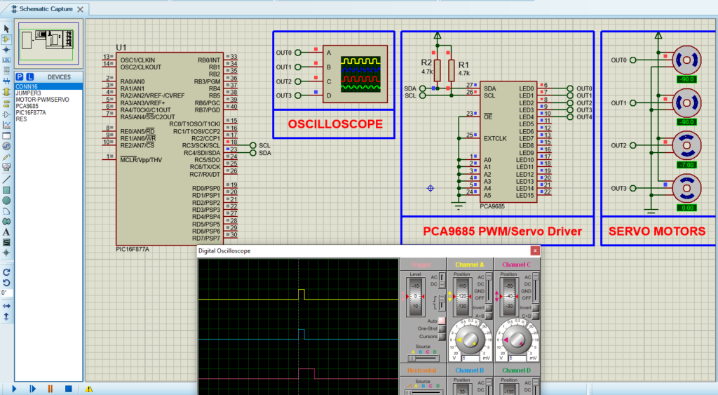
That’s all!
If you have any questions or suggestions don’t hesitate to leave a comment below
