In this article, learn how to interface the MCP9801 temperature sensor with the PIC16F877A microcontroller using I2C communication for accurate and reliable temperature sensing in your projects.
MCP9801 Temperature Sensor: Features, Applications, and Implementation with PIC Microcontroller
In this project, we will explore how to interface the MCP9801 temperature sensor with the PIC16F877A microcontroller. The MCP9801 is a high-accuracy digital temperature sensor with I2C communication, making it perfect for precise temperature monitoring and control in embedded systems. If you found this guide helpful, you might also like our similar projects on interfacing the LM75A and TCN75A temperature sensors for more temperature sensing solutions!
MCP9801 Overview
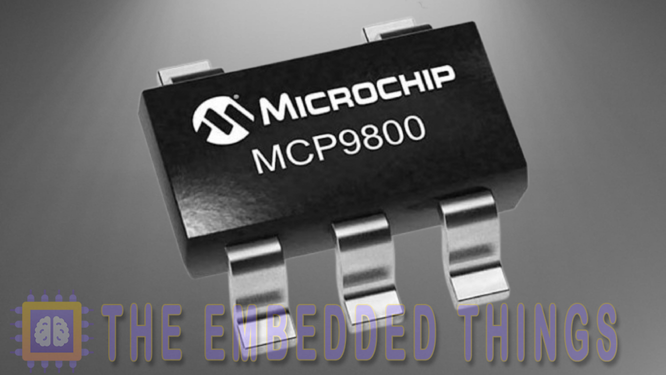
The MCP9801 is a high-precision digital temperature sensor from Microchip Technology, designed for accurate temperature monitoring in a wide range of applications. It operates over a temperature range of -55°C to +125°C, making it suitable for both industrial and consumer electronics. The sensor communicates via the I2C/SMBus interface, allowing seamless integration with microcontrollers like the PIC16F877A. With its 12-bit resolution, the MCP9801 delivers temperature readings with an accuracy of ±0.5°C at room temperature, ensuring reliable performance in critical environments. Its compact package options, including SOT-23-5, MSOP-8, and SOIC-8, make it ideal for space-constrained designs.
MCP9801 Features and Applications
Key Features:
- High Accuracy: ±0.5°C typical at +25°C, ±1°C from -10°C to +85°C.
- Wide Operating Voltage: 2.7V to 5.5V, compatible with most microcontroller systems.
- Low Power Consumption: Operating current of 200 µA (typical) and shutdown current of 1 µA (max).
- User-Configurable Resolution: Adjustable from 9-bit to 12-bit for flexibility in speed vs. precision.
- Programmable Alert Function: Configurable temperature limits with hysteresis for system protection.
- I2C/SMBus Interface: Supports up to 8 devices on a single bus, enabling multi-zone temperature monitoring.
Applications:
- PCs and Servers: Monitoring CPU and hard drive temperatures.
- Consumer Electronics: Temperature control in entertainment systems and mobile devices.
- Industrial Equipment: Ensuring safe operating temperatures in machinery.
- Data Communication Systems: Thermal management in networking hardware.
- General-Purpose Monitoring: Ideal for any application requiring precise temperature sensing.
MCP9801 Block Diagram
The MCP9801 integrates several key components to deliver its high-performance temperature sensing capabilities:
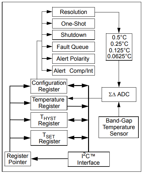
- Temperature Sensor: A band-gap sensor measures the ambient temperature by detecting changes in voltage across a transistor.
- ΣΔ ADC (Sigma-Delta Analog-to-Digital Converter): Converts the analog temperature signal into a digital value with configurable resolution (9-bit to 12-bit).
- Configuration Registers: Allow users to set parameters such as resolution, alert thresholds, and hysteresis.
- I2C/SMBus Interface: Facilitates communication with a host microcontroller for data transfer and configuration.
- Alert Output: Provides an open-drain output that can be configured as a comparator or interrupt signal for temperature limit alerts.
This integrated design ensures accurate temperature measurement, low power consumption, and easy integration into existing systems.
MCP9801: Practical Implementation Tips
When integrating the MCP9801 into your design, consider the following tips to maximize performance:
- Pull-Up Resistors: Ensure proper pull-up resistors (typically 4.7kΩ) are used on the SDA and SCL lines for reliable I2C communication.
- Decoupling Capacitors: Place a 0.1 µF to 1 µF ceramic capacitor close to the VDD pin to minimize noise and stabilize the power supply.
- Thermal Considerations: The MCP9801 measures the temperature of the PCB it is mounted on. For accurate ambient temperature readings, ensure good thermal contact with the environment and avoid heat-generating components nearby.
- Alert Configuration: Use the ALERT pin to trigger system responses, such as activating cooling fans or shutting down equipment when temperature limits are exceeded. Configure the alert polarity and hysteresis to suit your application.
- One-Shot Mode: For battery-powered applications, utilize the One-Shot mode to minimize power consumption. This mode performs a single temperature conversion and then returns to shutdown, reducing average current draw.
By following these guidelines, you can ensure optimal performance and reliability of the MCP9801 in your temperature monitoring system.
Project: Interfacing MCP9801 Temperature Sensor with PIC Microcontroller and LCD Display
This project integrates the MCP9801 digital temperature sensor with a PIC microcontroller using the I2C communication protocol. The system reads real-time temperature data and displays it on an LCD screen. The project also implements multiple operational modes, including One-Shot Mode, Comparator Mode, and Interrupt Mode, each with configurable temperature thresholds and hysteresis settings. Below is a detailed explanation of the code files used in the project.
I2C Driver Header File (i2c.h)
This header file defines the I2C driver functions for initializing and handling I2C communication between the microcontroller and the MCP9801 sensor.
#ifndef I2C_H
#define I2C_H

#include <xc.h>

// Define constants
#define _XTAL_FREQ             20000000
#define I2C_BaudRate           100000
#define SCL_D                  TRISC3
#define SDA_D                  TRISC4

// Function prototypes
void I2C_Master_Init(void);
void I2C_Master_Wait(void);
void I2C_Master_Start(void);
void I2C_Master_RepeatedStart(void);
void I2C_Master_Stop(void);
void I2C_ACK(void);
void I2C_NACK(void);
unsigned char I2C_Master_Write(unsigned char data);
unsigned char I2C_Read_Byte(void);

#endif
LCD Driver Header File (lcd.h)
This header file defines functions for initializing and controlling the LCD display, including clearing the screen, sending commands, and printing text.
#ifndef LCD_H
#define LCD_H
#include "i2c.h"
#define Line0               0x80
#define Line1               0xC0
void initializeLCD(void);
void clearLCD(void);
void sendCommandToLCD(unsigned char command);
void sendDataToLCD(unsigned char data);
void printToLCD(const char *string);
unsigned char moveCursorToPosition(unsigned char address);

#endif // LCD_H
Sensor Driver Header File (MCP980x.h)
This header file defines constants, configurations, and function prototypes for interacting with the MCP9801 sensor. It includes settings for resolution, alert modes, fault queues, and configuration registers.
#ifndef MCP980x_H
#define MCP980x_H
#include "i2c.h"
#include <stdint.h>
#include <stdbool.h>

// MCP9800 constants
#define MCP9800_ADDRESS     0x48
#define TEMP_REGISTER       0x00
#define CONFIG_REG          0x01
#define REG_HYSTERESIS      0x02
#define REG_LIMIT           0x03
#define TEMPERATURE_ERROR  -9990  // Error value

// ADC Resolution Values
#define ADC_RES_9BIT   0  // 9-bit resolution  (0.5C)
#define ADC_RES_10BIT  1  // 10-bit resolution (0.25C)
#define ADC_RES_11BIT  2  // 11-bit resolution (0.125C)
#define ADC_RES_12BIT  3  // 12-bit resolution (0.0625C)

// Alert Mode
#define MCP_COMPARATOR  0  // Alert pin active when temperature > alert value
#define MCP_INTERRUPT   1  // Alert pin asserted and reset by a microcontroller

// Fault Queue Types
#define MCP_1_FAULT     0  // Allow 1 fault before alert
#define MCP_2_FAULTS    1  // Allow 2 faults before alert
#define MCP_4_FAULTS    2  // Allow 4 faults before alert
#define MCP_6_FAULTS    3  // Allow 6 faults before alert

enum configuration {
    CONFIG_SHUTDOWN     = 0, // Bit 0 shutdown mode
    CONFIG_COMP_INT     = 1, // Bit 1 comparator/interrupt mode
    CONFIG_ALERT_POL    = 2, // Bit 2 alert polarity
    CONFIG_FAULT_QUEUE  = 3, // Bits 3-4 fault queue
    CONFIG_ADC_RES      = 5, // Bits 5-6 ADC resolution
    CONFIG_ONE_SHOT     = 7  // Bit 7 one shot mode
};

// Function prototypes
void MCP9800_Init(void);
void MCP9800_SetConfigOneShot(uint8_t enable);
void MCP9800_SetConfigResolution(uint8_t resolution);
void MCP9800_SetConfigFaultQueue(uint8_t fault_queue);
void MCP9800_SetConfigAlertPolarity(uint8_t polarity);
void MCP9800_SetConfigCompIntMode(uint8_t mode);
void MCP9800_SetConfigShutdown(uint8_t enable);
void MCP9800_WriteConfig(uint8_t value);
uint8_t MCP9800_ReadConfig(void);

uint8_t MCP9800_GetConfigOneShot(void);
uint8_t MCP9800_GetConfigResolution(void);
uint8_t MCP9800_GetConfigFaultQueue(void) ;
uint8_t MCP9800_GetConfigAlertPolarity(void);
uint8_t MCP9800_GetConfigCompIntMode(void);
uint8_t MCP9800_GetConfigShutdown(void);

int16_t MCP9800_ReadTemperature(void);
void MCP9800_SetHYST_Temp(int16_t temperature);
int16_t MCP9800_GetHYST_Temp(void) ;
void MCP9800_SetLIMIT_Temp(int16_t temperature) ;
int16_t MCP9800_GetLIMIT_Temp(void) ;
#endif // MCP9800_H
Main Application File (main.c)
This file initializes the hardware, reads temperature data from the MCP9801 sensor, and displays it on the LCD. It also handles button presses to switch between different operational modes.
#include "MCP980x.h"
#include "lcd.h"
#include <xc.h>
#include <stdio.h>

char displayString[16];

void initializeHardware(void);
void configureOneShotMode(void);
void configureShutdownMode(void);
void configureComparatorMode(void);
void configureInterruptMode(void);
void handleButtonPress(void);

int main(void) {

    initializeHardware();
    clearLCD();
    moveCursorToPosition(0);
    printToLCD("MCP9800 Ready");
    __delay_ms(1000);

    while (1) {
        handleButtonPress();
        float temp = MCP9800_ReadTemperature();
        moveCursorToPosition(Line1);
        snprintf(displayString, sizeof(displayString), "Temp: %.2f C", temp);
        moveCursorToPosition(0);
        printToLCD(displayString);
        __delay_ms(2000);
        }
    return 0;
    }

void initializeHardware(void) {
    TRISAbits.TRISA0 = 1;
    TRISAbits.TRISA1 = 1;
    TRISAbits.TRISA2 = 1;

    ADCON1 = 0x06;

    initializeLCD();
    MCP9800_Init();
    }

void handleButtonPress(void) {
    if (RA0 == 1) {
        configureOneShotMode();
        clearLCD();
        moveCursorToPosition(Line0);
        printToLCD("Mode: One-Shot");
    } else if (RA1 == 1) {
        configureComparatorMode();
        clearLCD();
        moveCursorToPosition(Line0);
        printToLCD("Mode: Comparator");
    } else if (RA2 == 1) {
        configureInterruptMode();
        clearLCD();
        moveCursorToPosition(Line0);
        printToLCD("Mode: Interrupt");
    }
}

void configureOneShotMode(void) {
    MCP9800_SetConfigResolution(ADC_RES_9BIT);
    MCP9800_SetConfigShutdown(1);
    MCP9800_SetConfigOneShot(1);
    __delay_ms(30);
    }

void configureContinuousConversionMode(void){
    MCP9800_SetConfigResolution(ADC_RES_9BIT);
    MCP9800_SetConfigShutdown(0);
    MCP9800_SetConfigOneShot(0);
    __delay_ms(30);
    }

void configureComparatorMode(void) {
    configureContinuousConversionMode();
    MCP9800_SetConfigShutdown(1);
    MCP9800_SetLIMIT_Temp(60);
    MCP9800_SetHYST_Temp(55);
    MCP9800_SetConfigShutdown(0);
    MCP9800_SetConfigAlertPolarity(0);
    MCP9800_SetConfigResolution(ADC_RES_12BIT);
    MCP9800_SetConfigFaultQueue(MCP_4_FAULTS);
    MCP9800_SetConfigCompIntMode(MCP_COMPARATOR);
    }

void configureInterruptMode(void) {
    configureContinuousConversionMode();
    MCP9800_SetConfigShutdown(1);
    MCP9800_SetLIMIT_Temp(70);
    MCP9800_SetHYST_Temp(65);
    MCP9800_SetConfigShutdown(0);
    MCP9800_SetConfigAlertPolarity(0);
    MCP9800_SetConfigResolution(ADC_RES_12BIT);
    MCP9800_SetConfigFaultQueue(MCP_2_FAULTS);
    MCP9800_SetConfigCompIntMode(MCP_INTERRUPT);
    }
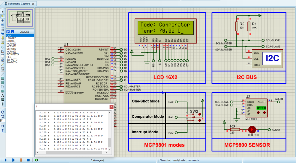
Proteus Configuration :
- Open Proteus & Create New Project and click next
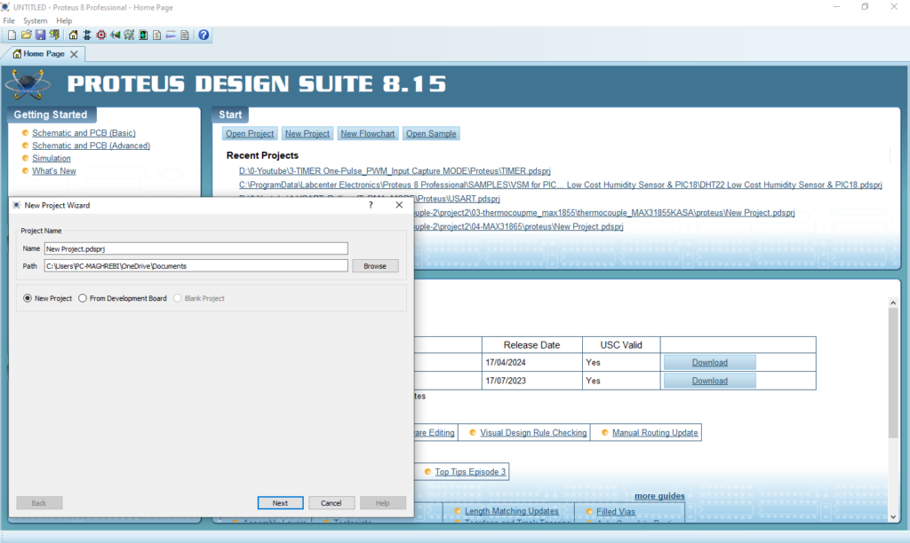
- Click on Pick Device
- Search for PIC16F877A & MCP9801& SWITCH-3P & RESISTOR & LCD 16X2
- Click on Virtual Instruments Mode then choose I2C DEBUGGER

- Click on Terminal Mode then choose (DEFAULT & POWER &GROUND)
- finally make the circuit below and start the simulation
That’s all!
If you have any questions or suggestions don’t hesitate to leave a comment below
