In this article, discover how to connect the MCP3421 to the PIC16F877A microcontroller, enabling high-accuracy sensor data collection through I2C communication.
MCP3421 18-Bit ADC: Interfacing, Features, and Applications with PIC Microcontroller
In this project, we will explore how to interface the MCP3421 18-bit ADC with the PIC16F877A microcontroller to create a high-precision sensor data acquisition system for accurate voltage measurement and analysis.
MCP3421 Overview
The MCP3421 is a high-precision, 18-bit delta-sigma analog-to-digital converter (ADC) designed for applications requiring accurate and reliable analog data conversion. It features a differential input architecture, which allows it to measure the difference between two input voltages, making it highly suitable for applications where common-mode noise needs to be rejected. The device operates with a single supply voltage ranging from 2.7V to 5.5V and communicates over an I²C interface, making it easy to integrate into a wide range of systems. Additionally, the MCP3421 includes an onboard precision voltage reference and a programmable gain amplifier (PGA), which enhances its flexibility in various measurement scenarios.
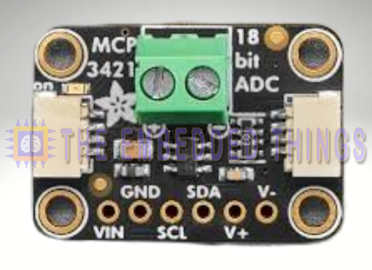
MCP3421 Features and Applications
Key Features:
- High Resolution: With up to 18 bits of resolution, the MCP3421 provides exceptional accuracy for precise measurements.
- Differential Inputs: The differential input structure allows for the rejection of common-mode noise, making it ideal for noisy environments.
- Onboard PGA: The programmable gain amplifier (PGA) with gains of 1, 2, 4, or 8 allows for the measurement of small input signals with high resolution.
- I²C Interface: The device communicates over a two-wire I²C interface, supporting standard, fast, and high-speed modes.
- Low Power Consumption: The MCP3421 offers low power operation, making it suitable for battery-powered applications.
- Self-Calibration: The device performs automatic self-calibration for each conversion, ensuring consistent and accurate results over time and temperature variations.
Typical Applications:
- Portable Instrumentation: The MCP3421 is well-suited for portable devices where precision and low power consumption are critical.
- Weigh Scales and Fuel Gauges: Its high resolution and differential input capability make it ideal for applications requiring precise measurements.
- Temperature Sensing: With its ability to interface with various sensors like RTDs, thermistors, and thermocouples, the MCP3421 is a versatile choice for temperature sensing applications.
- Bridge Sensing: Commonly used in pressure, strain, and force sensing applications where differential measurements are required.
MCP3421 Block Diagram
The MCP3421 consists of several key components that work together to provide high-precision analog-to-digital conversion:
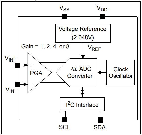
- Programmable Gain Amplifier (PGA): Amplifies the input signal by a factor of 1, 2, 4, or 8.
- Delta-Sigma ADC: Converts the amplified analog signal into a digital representation with up to 18 bits of resolution.
- Onboard Reference: Provides a stable 2.048V reference voltage for accurate measurements.
- I²C Interface: Allows communication with a microcontroller or other master device.
- Oscillator: Generates the internal clock signals required for the conversion process.
- Configuration Register: Stores settings for the device, such as PGA gain, conversion mode, and data rate.
MCP3421 Standout Feature: Self-Calibration
One of the notable features of the MCP3421 is its ability to perform automatic self-calibration for each conversion, ensuring consistent accuracy over time and temperature variations. This feature is crucial for maintaining precision in dynamic environments.
Project: Interfacing MCP3421 ADC with PIC Microcontroller for Precision Voltage Measurement
This project demonstrates how to interface the MCP3421 18-bit ADC with a PIC microcontroller to measure voltage with high precision. The system uses I2C for communication with the MCP3421 and UART to display the measured voltage in millivolts (mV) on a serial monitor. Below is a detailed explanation of the code files used in the project:
Main Header File (main.h)
This header file defines the configuration bits for the PIC microcontroller, sets the oscillator frequency, and includes necessary libraries.
#ifndef MAIN_H
#define MAIN_H

#include <xc.h>
#include <stdint.h>
#include <stdio.h>

// Configuration Bits
#pragma config FOSC = XT       // Oscillator Selection bits (XT oscillator)
#pragma config WDTE = OFF      // Watchdog Timer Enable bit (WDT disabled)
#pragma config PWRTE = OFF     // Power-up Timer Enable bit (PWRT disabled)
#pragma config BOREN = ON      // Brown-out Reset Enable bit (BOR enabled)
#pragma config LVP = OFF       // Low-Voltage Programming Disable
#pragma config CPD = OFF       // Data EEPROM Memory Code Protection bit (Data EEPROM code protection off)
#pragma config WRT = OFF       // Flash Program Memory Write Enable bits (Write protection off)
#pragma config CP = OFF        // Flash Program Memory Code Protection bit (Code protection off)

#define _XTAL_FREQ 16000000  // Oscillator Frequency (16MHz)

#endif /* MAIN_H */
UART Header File (uart.h)
This header file defines the UART functions for initializing and handling serial communication between the PIC microcontroller and an external device (e.g., a PC or another microcontroller)
#ifndef UART_H
#define UART_H
#include "main.h"

// Function prototypes
void UART_TX_Init(void);              // Initialize UART for transmission
uint8_t UART_TX_Empty(void);          // Check if UART transmit buffer is empty
void UART_Write(uint8_t data);        // Write a single byte to UART
void UART_Write_Text(const char* text); // Write a string to UART

#endif // UART_H
I2C Header File (i2c.h)
This header file defines the constants, pin configurations, and function prototypes for the I2C communication protocol. It is used to interface with the MCP3421 ADC and other I2C devices.
#ifndef I2C_H
#define I2C_H

#include "main.h"

// I2C Baud Rate (100 kHz)
#define I2C_BaudRate 100000

// Pin Direction Configuration
#define SCL_D TRISC3  // SCL Pin Direction (TRISC3 for PIC16F877A)
#define SDA_D TRISC4  // SDA Pin Direction (TRISC4 for PIC16F877A)

// Function Prototypes
void I2C_Master_Init(void);              // Initialize I2C in Master mode
void I2C_Master_Wait(void);              // Wait for I2C operation to complete
void I2C_Master_Start(void);             // Send I2C Start condition
void I2C_Master_RepeatedStart(void);     // Send I2C Repeated Start condition
void I2C_Master_Stop(void);              // Send I2C Stop condition
void I2C_ACK(void);                      // Send I2C Acknowledge (ACK)
void I2C_NACK(void);                     // Send I2C Not Acknowledge (NACK)
unsigned char I2C_Master_Write(unsigned char data);  // Write a byte to I2C
unsigned char I2C_Read_Byte(void);       // Read a byte from I2C

#endif
MCP3421 Header File (MCP3421.h)
This header file defines the MCP3421 ADC’s configuration constants, struct, and function prototypes for initializing and reading data from the ADC.
#ifndef MCP3421_H
#define MCP3421_H

#include "main.h"
#include "i2c.h"

// MCP3421 Configuration Constants
#define MCP3421_RDY_BIT   7  // Ready bit in configuration register
#define MCP3421_OC_BIT    4  // Conversion mode bit

// MCP3421 Struct for Storing Configuration
typedef struct {
    int address;     // I2C address
    uint8_t sr;      // Sample Rate
    uint8_t pga;     // PGA Gain
    uint8_t config;  // Configuration Byte
} MCP3421;

// Function Prototypes
void MCP3421_Init(MCP3421 *adc, int address, uint8_t sr, uint8_t pga);  // Initialize MCP3421
long MCP3421_GetLong(MCP3421 *adc);  // Get raw ADC value
double MCP3421_GetDouble(MCP3421 *adc);  // Get voltage in double format
int MCP3421_Ready(MCP3421 *adc);  // Check if ADC is ready for a new conversion

#endif // MCP3421_H
Main Source File (main.c)
This file contains the main logic for reading voltage data from the MCP3421 ADC and transmitting it over UART for monitoring. It initializes the UART and I2C interfaces, reads the ADC values, and displays them in a user-friendly format.
#include "main.h"
#include "uart.h"
#include "i2c.h"
#include "MCP3421.h"

void main(void) {
    // Initialize UART and I2C modules
    UART_TX_Init();
    I2C_Master_Init();

    // Initialize MCP3421 ADC
    MCP3421 adc;
    MCP3421_Init(&adc, 0x68, 2, 0);  // Address 0x68, 16-bit resolution, PGA x1

    // Main loop
    while (1) {
        // Check if MCP3421 is ready for a new conversion
        if (MCP3421_Ready(&adc)) {
            // Get the voltage reading
            double voltage = MCP3421_GetDouble(&adc);
            double millivolts = voltage * 1000;  // Convert to millivolts

            // Convert voltage to string and send via UART
            char buffer[20];
            sprintf(buffer, "Voltage: %.2f mV\n\r", millivolts);
            UART_Write_Text(buffer);

            // Delay before next reading
            __delay_ms(1000);
        }
    }
}
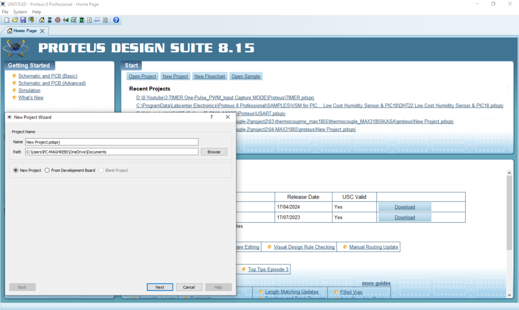
Proteus Configuration :
- Open Proteus & Create New Project and click next
- Click on Pick Device
- Search for PIC16F877A & MCP3421 & POTENTIOMETRE & RES
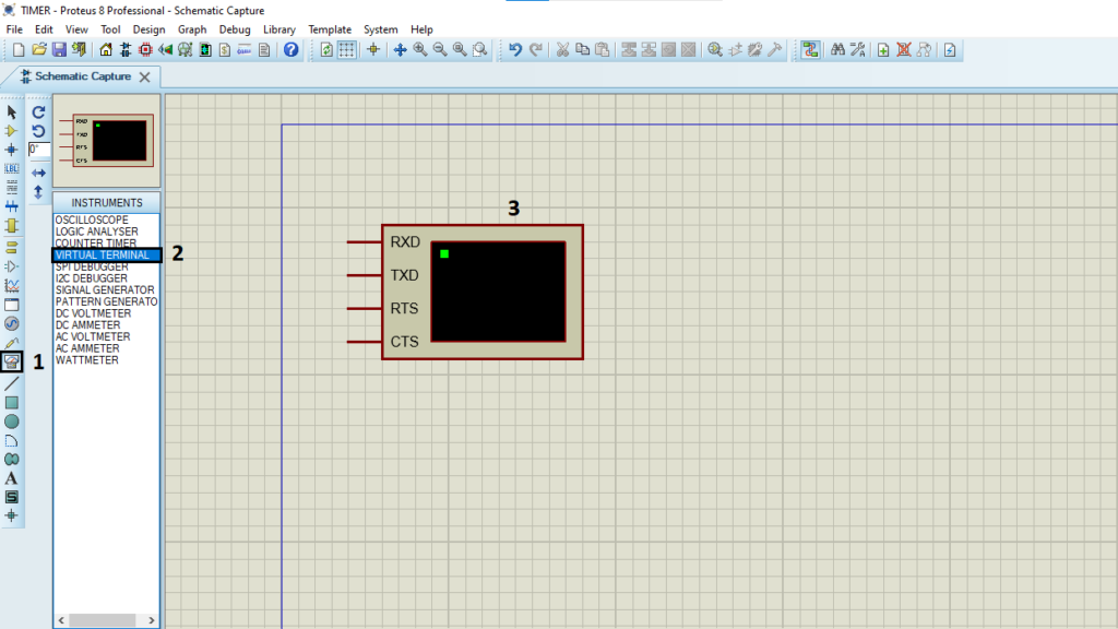
- Click on Virtual Instruments Mode then choose TERMINAL
- Click on Terminal Mode then choose (DEFAULT & POWER &GROUND)
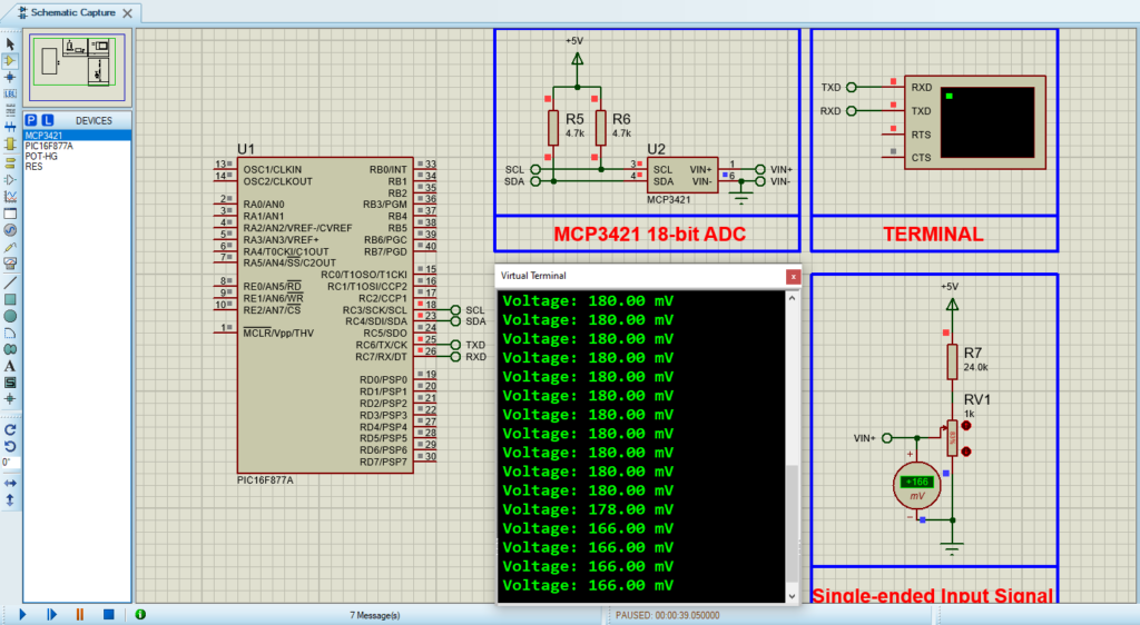
- finally make the circuit below and start the simulation
That’s all!
If you have any questions or suggestions don’t hesitate to leave a comment below
