In this article, explore PIC16F877A DS3232 RTC Communication to achieve precise timekeeping and enhance your microcontroller projects.

Interfacing DS3232 RTC Module with PIC16F877A: Accurate Timekeeping and Integration Guide
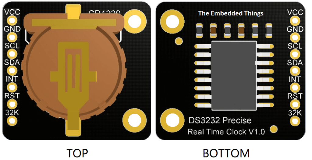
In this project, we will explore how to integrate the DS3232 real-time clock (RTC) module with the PIC16F877A microcontroller. The DS3232 is a temperature-compensated crystal oscillator with an integrated RTC and battery-backed SRAM. With its precise timekeeping capabilities and programmable alarms, it offers a robust solution for time-sensitive applications. Building on the principles of RTC integration, another project, ‘Real-Time Clock (RTC) and Its Application in STM32,’ demonstrates similar concepts applied to the STM32 microcontroller, highlighting the versatility and wide-ranging applications of RTCs in different embedded systems
DS3232 Overview
The DS3232 provides accurate timekeeping with features such as battery backup, temperature compensation, and integrated SRAM. It tracks seconds, minutes, hours, days, months, and years, including automatic adjustment for leap years. Its I2C interface simplifies integration with various microcontrollers.

Features and Applications
Key Features:
- High Accuracy: ±2 ppm from 0°C to +40°C; ±3.5 ppm from -40°C to +85°C.
- Battery Backup: Ensures continuous timekeeping during power interruptions.
- Operating Ranges: Supports commercial and industrial temperatures (-40°C to +85°C).
- Integrated SRAM: Provides 236 bytes of battery-backed memory.
- Alarm and Output Options: Two time-of-day alarms and programmable square-wave output.
- I2C Interface: Supports both standard (100 kHz) and fast (400 kHz) modes.
Applications:
- Power meters
- GPS systems
- Telematics
- Servers and industrial automation
DS3232 Block Diagram
The DS3232 comprises several functional blocks that work together to provide precise timekeeping and versatile functionality. The RTC and temperature-compensated crystal oscillator (TCXO) ensure accurate time maintenance while compensating for temperature variations. Its power management system seamlessly switches between the primary power source and the backup battery to maintain uninterrupted operation. The module also includes an alarm and square-wave generator, which allows for the configuration of time-based alarms and the generation of programmable output signals. Additionally, the integrated I2C communication interface facilitates efficient and reliable data exchange with the microcontroller, ensuring smooth integration into a wide range of applications.

Project : Interfacing DS3231 RTC with PIC16F877A
This project demonstrates the integration of the DS3231 real-time clock (RTC) module with the PIC16F877A microcontroller using I²C communication. The setup allows the system to display real-time clock data on an LCD, with options to set the time and date using push buttons. The DS3231 module ensures accurate timekeeping, even during power outages, thanks to its built-in battery backup and temperature compensation features.
Configuration and Initialization
This section configures the PIC16F877A, including oscillator settings, timer options, and pin configurations. Constants and global variables define RTC addresses, button pins, and storage for time and date strings, while function prototypes outline key operations for LCD updates and user interactions.
/**
 * @file main.c
 * @brief LCD Display with DS3231 RTC
 * @details Real-time clock display with setting capabilities for PIC16F877A
 */
#include <xc.h>
#include <stdio.h>
#include "i2c.h"
#include "jhd_lcd.h"

// PIC16F877A Configuration Bit Settings
#pragma config FOSC = HS   // Oscillator Selection bits (HS oscillator)
#pragma config WDTE = OFF  // Watchdog Timer Enable bit (WDT disabled)
#pragma config PWRTE = OFF // Power-up Timer Enable bit (PWRT disabled)
#pragma config BOREN = ON  // Brown-out Reset Enable bit (BOR enabled)
#pragma config LVP = OFF   // Low-Voltage Programming Enable bit
#pragma config CPD = OFF   // Data EEPROM Memory Code Protection bit
#pragma config WRT = OFF   // Flash Program Memory Write Enable bits
#pragma config CP = OFF    // Flash Program Memory Code Protection bit

// Constants
#define LCD_ADDRESS     0x7C
#define DS3231_ADDRESS  0xD0
#define BUTTON1         PORTBbits.RB0
#define BUTTON2         PORTBbits.RB1
#define _XTAL_FREQ     16000000

// Global variables
char time[]     = "TIME:  :  :  ";
char calendar[] = "DATE:  /  /20  ";
uint8_t i, second, minute, hour, date, month, year;

// Function prototypes
void DS3231_display(void);
void blink(void);
uint8_t edit(uint8_t parameter, uint8_t xx, uint8_t yy);
Utility Functions
Utility functions handle essential conversions and display updates. bcd_to_decimal and decimal_to_bcd convert between BCD and decimal formats, while DS3231_display formats and shows the time and date on the LCD. The blink function provides visual feedback during user interactions.
// Convert BCD to decimal
uint8_t bcd_to_decimal(uint8_t bcd) {
    return ((bcd >> 4) * 10 + (bcd & 0x0F));
}

// Convert decimal to BCD
uint8_t decimal_to_bcd(uint8_t decimal) {
    uint8_t tens = decimal / 10;
    uint8_t ones = decimal % 10;
    return ((tens << 4) | ones);
}

void DS3231_display(void) {
    second = bcd_to_decimal(second);
    minute = bcd_to_decimal(minute);
    hour   = bcd_to_decimal(hour);
    date   = bcd_to_decimal(date);
    month  = bcd_to_decimal(month);
    year   = bcd_to_decimal(year);

    // Update time string
    time[12] = second % 10 + '0';
    time[11] = second / 10 + '0';
    time[9] = minute % 10 + '0';
    time[8] = minute / 10 + '0';
    time[6] = hour % 10 + '0';
    time[5] = hour / 10 + '0';

    // Update calendar string
    calendar[14] = year % 10 + '0';
    calendar[13] = year / 10 + '0';
    calendar[9] = month % 10 + '0';
    calendar[8] = month / 10 + '0';
    calendar[6] = date % 10 + '0';
    calendar[5] = date / 10 + '0';

    // Display on LCD
    LCD_SetCursor(0, 0);
    LCD_Print_String(time);
    LCD_SetCursor(0, 1);
    LCD_Print_String(calendar);
}

void blink(void) {
    uint8_t j = 0;
    while(j < 10 && BUTTON1 && BUTTON2) {
        j++;
        __delay_ms(25);
    }
}
Main Application Logic
The main logic manages user interaction, real-time updates, and RTC communication. The edit function enables parameter modification with button presses, while DS3231_write and DS3231_read handle I²C communication to update or retrieve RTC data. The main loop continuously updates the display and listens for user input.
uint8_t edit(uint8_t parameter, uint8_t xx, uint8_t yy) {
    char temp[3];
    while(!BUTTON1);
    while(1) {
        while(!BUTTON2) {
            parameter++;
            if(i == 0 && parameter > 23) parameter = 0;  // Hours
            if(i == 1 && parameter > 59) parameter = 0;  // Minutes
            if(i == 2 && parameter > 31) parameter = 1;  // Date
            if(i == 3 && parameter > 12) parameter = 1;  // Month
            if(i == 4 && parameter > 99) parameter = 0;  // Year
            LCD_SetCursor(xx, yy);
            sprintf(temp, "%02u", parameter);
            LCD_Print_String(temp);
            __delay_ms(200);
        }
        LCD_SetCursor(xx, yy);
        LCD_Print_String("  ");
        blink();
        LCD_SetCursor(xx, yy);
        sprintf(temp, "%02u", parameter);
        LCD_Print_String(temp);
        blink();
        if(!BUTTON1) {
            i++;
            return parameter;
        }
    }
}

void DS3231_write(void) {
    I2C_Master_Start();
    I2C_Master_Write(DS3231_ADDRESS);
    I2C_Master_Write(0x00);
    I2C_Master_Write(0x00);
    I2C_Master_Write(decimal_to_bcd(minute));
    I2C_Master_Write(decimal_to_bcd(hour));
    I2C_Master_Write(1);
    I2C_Master_Write(decimal_to_bcd(date));
    I2C_Master_Write(decimal_to_bcd(month));
    I2C_Master_Write(decimal_to_bcd(year));
    I2C_Master_Stop();
}

void DS3231_read(void) {
    I2C_Master_Start();
    I2C_Master_Write(DS3231_ADDRESS);
    I2C_Master_Write(0x00);
    I2C_Master_RepeatedStart();
    I2C_Master_Write(DS3231_ADDRESS | 0x01);
    second = I2C_Read_Byte(); I2C_ACK();
    minute = I2C_Read_Byte(); I2C_ACK();
    hour = I2C_Read_Byte(); I2C_ACK();
    I2C_Read_Byte(); I2C_ACK();
    date = I2C_Read_Byte(); I2C_ACK();
    month = I2C_Read_Byte(); I2C_ACK();
    year = I2C_Read_Byte(); I2C_NACK();
    I2C_Master_Stop();
}

void main(void) {
    TRISB = 0xFF;
    OPTION_REGbits.nRBPU = 0;
    I2C_Master_Init();
    LCD_Init(LCD_ADDRESS);
    LCD_Clear();
    while(1) {
        if(!BUTTON1) {
            i = 0;
            hour = edit(hour, 5, 0);
            minute = edit(minute, 8, 0);
            date = edit(date, 5, 1);
            month = edit(month, 8, 1);
            year = edit(year, 13, 1);
            DS3231_write();
            __delay_ms(200);
        }
        DS3231_read();
        DS3231_display();
        __delay_ms(50);
    }
}
Proteus Configuration :
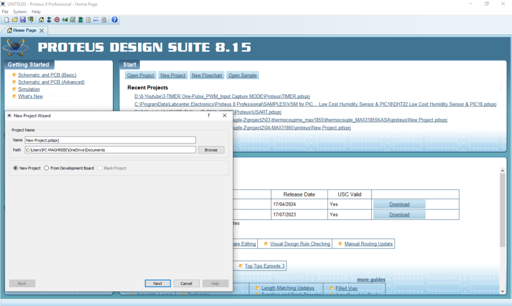
- Open Proteus & Create New Project and click next

- Click on Pick Device
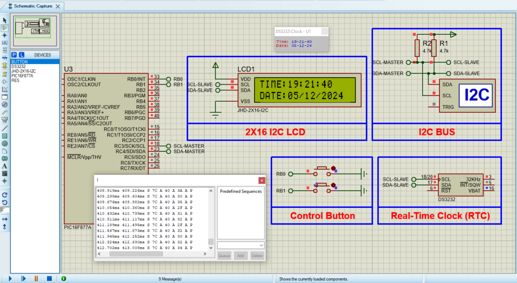
- Search for PIC16F877A & JHD-2X16-I2C & TCN75A
- Click on Virtual Instruments Mode then choose I2C DEBUGGER

- Click on Terminal Mode then choose (DEFAULT & POWER &GROUND)
- finally make the circuit below and start the simulation

That’s all!
If you have any questions or suggestions don’t hesitate to leave a comment below

2 comments
Hello, I have a question that I sent you by email. Thank you very much in advance.
I understand you’re waiting for a response. Unfortunately, I currently have an issue with my email. Could you please share your question here in a comment instead? I’ll be happy to assist you as soon as possible.