
In this article, we explore the use of MPX Sensors with the PIC16F877A microcontroller to create a reliable and cost-effective pressure measurement system.

Advanced Pressure Measurement System Using MPX4250A, MPX4115, and MPXA6115A Sensors with PIC16F877A Microcontroller
In this project, we explore the integration of three highly reliable pressure MPX Sensors MPX4250A, MPX4115, and MPXA6115A—with the PIC16F877A microcontroller to create a versatile and accurate pressure measurement system. These sensors, manufactured by NXP Semiconductors, are widely used in industrial, automotive, and environmental applications due to their high precision, temperature compensation, and robust design. By combining these sensors with the PIC16F877A, we can develop a system capable of handling a wide range of pressure measurements, from 15 kPa to 250 kPa, with high accuracy and reliability.
For alternative pressure and temperature sensing, consider the BMP180, a digital barometric sensor that measures both pressure and temperature.
Overview of the Sensors
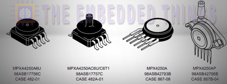
MPX4250A: High-Pressure Sensor (20 to 250 kPa)
Features:
- Measures absolute pressure from 20 to 250 kPa.
- On-chip signal conditioning and temperature compensation.
- High accuracy with a maximum error of 1.5% over 0°C to 85°C.
- Available in small outline and unibody packages.
Key Specifications:
- Output voltage range: 0.2V to 4.8V.
- Sensitivity: 20 mV/kPa.
- Temperature range: -40°C to +125°C.
Applications:
- Engine control
- turbo boost systems
- industrial pressure monitoring
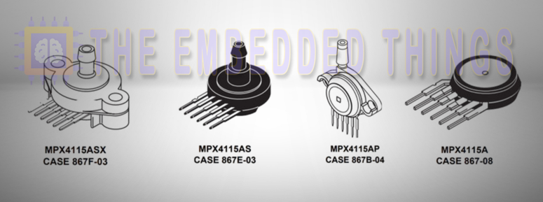
MPX4115: Barometric and Altitude Pressure Sensor (15 to 125 kPa)
Features:
- Measures absolute pressure from 15 to 125 kPa.
- On-chip signal conditioning and temperature compensation.
- High accuracy with a maximum error of 1.5% over 0°C to 85°C.
- Durable epoxy unibody design.
Key Specifications:
- Output voltage range: 0.2V to 4.8V.
- Sensitivity: 46 mV/kPa.
- Temperature range: -40°C to +125°C.
Applications:
- Altimeters
- barometers
- weather stations.
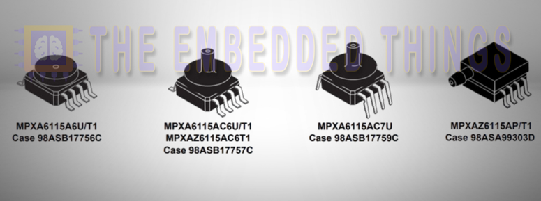
MPXA6115A: General-Purpose Pressure Sensor (15 to 115 kPa).
Features:
- Measures absolute pressure from 15 to 115 kPa.
- On-chip signal conditioning and temperature compensation.
- High accuracy with a maximum error of 1.5% over 0°C to 85°C.
- Resistant to high humidity and automotive media.
Key Specifications:
- Output voltage range: 0.2V to 4.8V.
- Sensitivity: 45 mV/kPa.
- Temperature range: -40°C to +125°C
Applications:
- Industrial controls
- engine management
- weather monitoring.
Block Diagram of MPX4250A, MPX4115, and MPXA6115A Pressure Sensors
Below is a detailed explanation of the block diagrams and functional components of the MPX Sensors MPX4250A, MPX4115, and MPXA6115A pressure sensors.
Common Features in Block Diagrams
- Sensing Element: All three sensors (MPX4250A, MPX4115, and MPXA6115A) use a silicon diaphragm with piezoresistive strain gauges to detect pressure changes. The diaphragm deforms under pressure, causing a change in resistance, which is converted into an electrical signal.
- Temperature Compensation: All three sensors include on-chip temperature compensation to ensure accurate readings across a wide temperature range (-40°C to +125°C). This feature minimizes errors caused by temperature variations.
- Gain Stage: All three sensors have at least one gain stage to amplify the small signal from the sensing element, ensuring a linear and proportional output relative to the applied pressure.
- Analog Output: All three sensors provide an analog voltage output (Vout) proportional to the applied pressure, typically ranging from 0.2V to 4.8V, making them compatible with microcontrollers, ADCs, and other digital systems.
Specific Differences in Block Diagrams
The MPX4250A has dual gain stages with ground reference shift circuitry, making it ideal for high-precision automotive applications like MAP sensing.
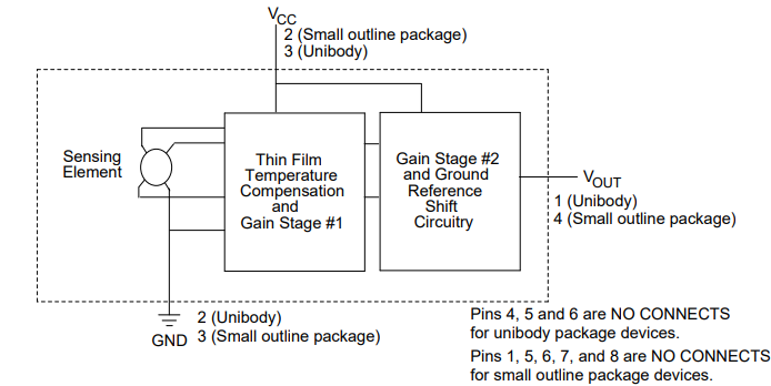
The MPX4115 uses a single gain stage and is designed for altimeter and barometer applications, where simplicity and accuracy are key.
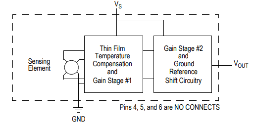
The MPXA6115A also uses a single gain stage but is optimized for industrial and environmental applications, with added resistance to harsh media.
Project: Interfacing MPX4250A, MPX4115, and MPXA6115A Pressure Sensors with PIC16F877A for Advanced Pressure Measurement
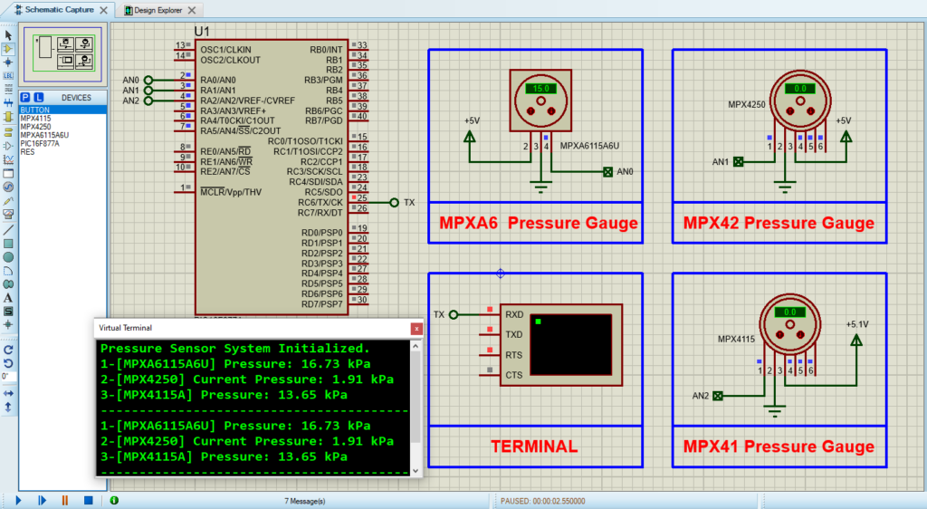
This project demonstrates how to interface three pressure sensors—MPX4250A, MPX4115, and MPXA6115A—with a PIC16F877A microcontroller to create a versatile pressure measurement system. The system uses the microcontroller’s 10-bit ADC to read analog voltage outputs from the sensors, converts them to pressure values, and transmits the results over UART for monitoring. Below is a detailed explanation of the code files used in the project:
Main Header File (main.h)
This header file defines the configuration bits for the PIC microcontroller, sets the oscillator frequency, and includes necessary libraries.
#ifndef MAIN_H
#define MAIN_H

#include <xc.h>
#include <stdint.h>
#include <stdio.h>
#include <math.h>

// Configuration Bits
#pragma config FOSC = HS        // High-Speed Crystal Oscillator
#pragma config WDTE = OFF       // Watchdog Timer Disabled
#pragma config PWRTE = ON       // Power-up Timer Enabled
#pragma config BOREN = ON       // Brown-out Reset Enabled
#pragma config LVP = OFF        // Low-Voltage Programming Disabled
#pragma config CPD = OFF        // Data EEPROM Memory Code Protection Disabled
#pragma config WRT = OFF        // Flash Program Memory Write Disabled
#pragma config CP = OFF         // Flash Program Memory Code Protection Disabled

#define _XTAL_FREQ 16000000     // Oscillator Frequency (16MHz)

#endif /* MAIN_H */
UART Header File (uart.h)
This header file defines the UART functions for initializing and handling serial communication between the PIC microcontroller and an external device (e.g., a PC or another microcontroller).
#ifndef UART_H
#define UART_H

#include <xc.h>
#include <stdint.h>

// Function Prototypes
void UART_TX_Init(void);              // Initialize UART for transmission
uint8_t UART_TX_Empty(void);          // Check if UART transmit buffer is empty
void UART_Write(uint8_t data);        // Write a single byte to UART
void UART_Write_Text(const char* text); // Write a string to UART
uint8_t UART_Read(void);              // Read a single byte from UART
void UART_Read_Text(char* buffer, uint8_t max_length); // Read a string from UART

#endif // UART_H
Main Source File (main.c)
This file contains the main logic for reading pressure data from the MPX4250A, MPX4115, and MPXA6115A sensors, converting the ADC readings to pressure values, and transmitting the results over UART for monitoring.
#include "main.h"
#include "uart.h"

// Define ADC Channels
#define PRESS_A6115 0           // Analog channel for MPXA6115A6U
#define SENSOR_MPX4250 1        // Analog channel for MPX4250
#define SENSOR_MPX4115A 2       // Analog channel for MPX4115A

// Define Constants for Pressure Calculations
#define SENSITIVITY_A6115 0.04585  // Sensitivity in V/kPa
#define OFFSET_A6115 -0.108        // Offset in V
#define ERROR_A6115 10             // Calibration error in kPa
#define VREF_A6115 5.0             // Reference Voltage for ADC

#define SENSITIVITY_MPX4250 0.0188 // Sensitivity in V/kPa
#define OFFSET_MPX4250 0.04        // Offset in V
#define ERROR_MPX4250 -10          // Calibration error in kPa
#define VREF_MPX4250 5.0           // Reference Voltage for ADC

#define SENSITIVITY_MPX4115A 0.0459 // Sensitivity in V/kPa
#define OFFSET_MPX4115A -0.095      // Offset in V
#define ERROR_MPX4115A 5.5          // Calibration error in kPa
#define VREF_MPX4115A 5.1           // Reference Voltage for ADC

#define ADC_RESOLUTION 1023.0       // ADC Resolution
volatile int peakMemory_MPX4250 = 0; // Peak pressure memory for MPX4250

// Function Prototypes
void Initialize_ADC(void);
unsigned int Read_ADC(unsigned char channel);
float pressure_A6115(void);
float readPressure_MPX4250(void);
float readPressure_MPX4115A(void);

// Initialize ADC
void Initialize_ADC(void) {
    TRISA = 0x07;     // Set RA0, RA1, and RA2 as inputs
    ADCON1 = 0x80;    // Configure AN0, AN1, and AN2 as analog, others digital
    ADCON0 = 0x41;    // ADC ON, Fosc/16
    __delay_ms(10);   // Stabilize ADC
}

// Read ADC Value
unsigned int Read_ADC(unsigned char channel) {
    ADCON0bits.CHS = channel;  // Select ADC channel
    __delay_ms(2);             // Delay for channel stabilization
    ADCON0bits.GO = 1;         // Start ADC conversion
    while (ADCON0bits.GO_nDONE); // Wait for conversion to complete
    return (ADRESH << 8) + ADRESL; // Return 10-bit ADC result
}

// Calculate pressure for MPXA6115A6U
float pressure_A6115() {
    unsigned int adcValue = Read_ADC(PRESS_A6115);
    float Vout = (adcValue / ADC_RESOLUTION) * VREF_A6115;  // Convert ADC to voltage
    return ((Vout - OFFSET_A6115) / SENSITIVITY_A6115) + ERROR_A6115; // Pressure in kPa
}

// Calculate pressure for MPX4250
float readPressure_MPX4250() {
    unsigned int adcValue = Read_ADC(SENSOR_MPX4250);
    float Vout = (adcValue / ADC_RESOLUTION) * VREF_MPX4250; // Convert ADC to voltage
    float pressure = (Vout - OFFSET_MPX4250) / SENSITIVITY_MPX4250; // Pressure in kPa

    // Update peak memory
    if (pressure > peakMemory_MPX4250) {
        peakMemory_MPX4250 = pressure + ERROR_MPX4250;
    }
    return pressure + ERROR_MPX4250;
}

// Calculate pressure for MPX4115A
float readPressure_MPX4115A() {
    unsigned int adcValue = Read_ADC(SENSOR_MPX4115A);
    float Vout = (adcValue / ADC_RESOLUTION) * VREF_MPX4115A;  // Convert ADC to voltage
    return ((Vout - OFFSET_MPX4115A) / SENSITIVITY_MPX4115A) + ERROR_MPX4115A; // Pressure in kPa
}

// Main Function
void main(void) {
    Initialize_ADC();
    UART_TX_Init();
    UART_Write_Text("Pressure Sensor System Initialized.\n\r");
    char buffer[50];

    while (1) {
        // Read and display MPXA6115A6U pressure
        float pressure_A6115_val = pressure_A6115();
        sprintf(buffer, "1-[MPXA6115A6U] Pressure: %.2f kPa\n\r", pressure_A6115_val);
        UART_Write_Text(buffer);

        // Read and display MPX4250 pressure
        float pressure_MPX4250_val = readPressure_MPX4250();
        sprintf(buffer, "2-[MPX4250] Current Pressure: %.2f kPa\n\r", pressure_MPX4250_val);
        UART_Write_Text(buffer);

        // Read and display MPX4115A pressure
        float pressure_MPX4115A_val = readPressure_MPX4115A();
        sprintf(buffer, "3-[MPX4115A] Pressure: %.2f kPa\n\r", pressure_MPX4115A_val);
        UART_Write_Text(buffer);
        UART_Write_Text("-----------------------------------------------\n\r");

        __delay_ms(2000); // Delay before the next reading
    }
}
Proteus Configuration :
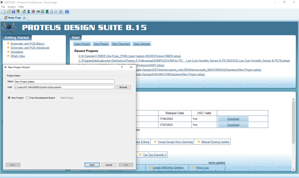
- Open Proteus & Create New Project and click next
- Click on Pick Device
- Search for PIC16F877A & MPXA6115A6U & MPX4250 & MPX4115
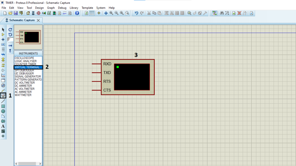
- Click on Virtual Instruments Mode then choose TERMINAL
- Click on Terminal Mode then choose (DEFAULT & POWER &GROUND)
- finally make the circuit below and start the simulation
That’s all!
If you have any questions or suggestions don’t hesitate to leave a comment below