In this article, learn how to interface the PIC16F877A microcontroller with the L9110 DC Motor Driver for efficient and precise DC motor control in your projects
L9110 DC Motor Driver: A Complete Guide to Motor Control with PIC16F877A for Robotics and Automation
In this project, we will guide you through interfacing the L9110 DC Motor Driver with the PIC16F877A microcontroller to create an efficient DC Motor Control System, perfect for robotics and automation applications. If you’re also interested in working with the L298 motor driver, don’t miss our detailed PIC16F877 L298 Motor Driver Guide
L9110 Overview
The L9110 is a versatile motor driver chip designed to control the movement of DC motors in various applications. With its dual-channel architecture and robust features, it is an excellent choice for projects ranging from robotics to automation. This article provides an in-depth look at the L9110, covering its key features, applications, and practical insights for effective implementation.
L9110 Features and Applications
Key Features:
- Dual-Channel Operation: The L9110 offers two independent channels, each capable of driving a DC motor in both forward and reverse directions. This dual-channel capability makes it ideal for applications requiring simultaneous control of two motors.
- High Current Handling: Each channel can handle a continuous current of up to 800mA, with a peak current capability of 2A. This high current rating ensures reliable operation even with power-hungry motors.
- Wide Voltage Range: Operates with a supply voltage ranging from 2.5V to 12V, making it suitable for a wide array of projects, including those powered by batteries.
- Low Quiescent Current: With a quiescent current of just a few microamperes, the L9110 is efficient and ideal for battery-powered applications where power consumption is a concern.
- Built-in Protection: Integrated clamp diodes protect against inductive spikes, ensuring safe operation when driving inductive loads like motors or relays.
Applications:
- Robotics: Perfect for controlling the movement of robots equipped with two DC motors, enabling precise forward, reverse, and stop commands.
- Automation: Suitable for automating machinery that requires controlled motor operations, such as conveyor belts or automated gates.
- DIY Projects: Ideal for hobbyists and enthusiasts looking to add motor control capabilities to their DIY projects
How It Works ?
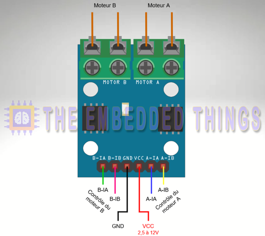
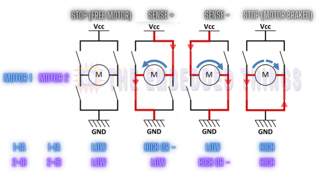
The L9110 operates by receiving input signals from a microcontroller or logic circuit, which it then amplifies to drive the motors. Each channel has an input pin (IA and IB) that controls the corresponding output pin (OA and OB). By applying the appropriate logic levels to these input pins, you can control the direction and speed of the connected motors.
Connections:
- Power Supply: Connect the VCC pin to the positive supply voltage and the GND pins to the negative supply voltage.
- Motor Connections: Connect the positive terminals of the motors to the OA and OB pins, and the negative terminals to the ground.
- Input Signals: Connect the IA and IB pins to the output pins of your microcontroller or logic circuit, ensuring that the logic levels are compatible with the L9110’s input thresholds.
Project: Interfacing L9110 DC Motor Driver with PIC16F877A Microcontroller
This project demonstrates how to interface the L9110 DC Motor Driver with a PIC16F877A microcontroller to control DC motors efficiently. The system enables bidirectional motor control (forward, reverse, and stop) using simple digital signals, making it ideal for robotics, automation, and DIY electronics projects. Below is a detailed explanation of the code files used in the project:
Main Header File (main.h)
This header file defines configuration bits, constants, and function prototypes for motor control and UART communication.
#ifndef MAIN_H
#define MAIN_H

#include <xc.h>

// Configuration Bits
#pragma config FOSC = HS        // High-Speed Oscillator
#pragma config WDTE = OFF       // Watchdog Timer Disabled
#pragma config PWRTE = ON       // Power-Up Timer Enabled
#pragma config BOREN = ON       // Brown-Out Reset Enabled
#pragma config LVP = OFF        // Low-Voltage Programming Disabled
#pragma config CPD = OFF        // Data EEPROM Memory Code Protection Disabled
#pragma config WRT = OFF        // Flash Program Memory Write Protection Disabled
#pragma config CP = OFF         // Flash Program Memory Code Protection Disabled

#define _XTAL_FREQ 16000000     // Oscillator Frequency (16MHz)

#endif /* MAIN_H */
UART Header File (uart.h)
This header file defines the UART functions for initializing and handling serial communication between the PIC microcontroller and an external device (e.g., a PC or another microcontroller).
#ifndef UART_H
#define UART_H
#include "main.h"

// Function prototypes
void UART_TX_Init(void);              // Initialize UART for transmission
uint8_t UART_TX_Empty(void);          // Check if UART transmit buffer is empty
void UART_Write(uint8_t data);        // Write a single byte to UART
void UART_Write_Text(const char* text); // Write a string to UART

#endif // UART_H
Main Source File (main.c)
This file contains the main logic for controlling the L9110 DC Motor Driver using the PIC16F877A microcontroller. It includes motor control functions and UART communication for remote control
#include <xc.h>
#include "main.h"
#include "uart.h"

// Function Prototypes
void Motor_Init(void);                // Initialize motor control pins
void Motor_Control(int motor, int cmd, int speed); // Control individual motors
void Motor_Forward(int speed);        // Move motors forward
void Motor_Backward(int speed);       // Move motors backward
void Motor_Right(int speed);          // Turn right
void Motor_Left(int speed);           // Turn left
void Motor_Stop(void);                // Stop all motors

// Global Variables for Motor Pins
unsigned char MOTOR1_IN1 = 0;
unsigned char MOTOR1_IN2 = 1;
unsigned char MOTOR2_IN1 = 2;
unsigned char MOTOR2_IN2 = 3;

void main(void) {
    // Initialize the motor pins and UART
    Motor_Init();
    UART_TX_Init();
    UART_Write_Text("L9110s_Diagnostic READY !\n\r");
    UART_Write_Text("1 --> Forward, 2 --> Backward, 3 --> Left, 4 --> Right, 5 --> STOP, 6 --> Help\n\r");

    while (1) {
        if (RCIF) { // Check if UART data is available
            char input = RCREG; // Read the received character

            switch (input) {
                case '1':
                    Motor_Forward(255); // Full speed forward
                    UART_Write_Text("Forward\n\r");
                    break;
                case '2':
                    Motor_Backward(255); // Full speed backward
                    UART_Write_Text("Backward\n\r");
                    break;
                case '3':
                    Motor_Left(255); // Full speed left
                    UART_Write_Text("Left\n\r");
                    break;
                case '4':
                    Motor_Right(255); // Full speed right
                    UART_Write_Text("Right\n\r");
                    break;
                case '5':
                    Motor_Stop(); // Stop the motors
                    UART_Write_Text("Stopped\n\r");
                    break;
                case '6':
                    UART_Write_Text("1 --> Forward, 2 --> Backward, 3 --> Left, 4 --> Right, 5 --> STOP, 6 --> Help\n\r");
                    break;
                default:
                    UART_Write_Text("Invalid Command\n\r");
                    break;
            }
            __delay_ms(500); // Debounce delay
        }
    }
}

// Initialize the motor control pins
void Motor_Init(void) {
    TRISBbits.TRISB0 = 0;
    TRISBbits.TRISB1 = 0;
    TRISBbits.TRISB2 = 0;
    TRISBbits.TRISB3 = 0;
    PORTB = 0; // Ensure all motor control pins are low initially
}

// Control individual motors
void Motor_Control(int motor, int cmd, int speed) {
    unsigned char in1, in2;

    if (motor == 1) {
        in1 = MOTOR1_IN1;
        in2 = MOTOR1_IN2;
    } else if (motor == 2) {
        in1 = MOTOR2_IN1;
        in2 = MOTOR2_IN2;
    } else {
        return; // Invalid motor
    }

    switch (cmd) {
        case 1: // Forward
            PORTB |= (1 << in1);
            PORTB &= ~(1 << in2);
            break;
        case 2: // Reverse
            PORTB &= ~(1 << in1);
            PORTB |= (1 << in2);
            break;
        case 3: // Stop
            PORTB &= ~(1 << in1);
            PORTB &= ~(1 << in2);
            break;
        default:
            break;
    }

    // Simulating speed control by PWM (simple delay-based approach for demonstration)
    if (speed > 0) {
        for (int i = 0; i < speed; i++) {
            __delay_us(100);
        }
    }
}

// Move forward
void Motor_Forward(int speed) {
    Motor_Control(1, 1, speed);
    Motor_Control(2, 1, speed);
}

// Move backward
void Motor_Backward(int speed) {
    Motor_Control(1, 2, speed);
    Motor_Control(2, 2, speed);
}

// Turn right
void Motor_Right(int speed) {
    Motor_Control(1, 1, speed);
    Motor_Control(2, 2, speed);
}

// Turn left
void Motor_Left(int speed) {
    Motor_Control(1, 2, speed);
    Motor_Control(2, 1, speed);
}

// Stop all motors
void Motor_Stop(void) {
    Motor_Control(1, 3, 0);
    Motor_Control(2, 3, 0);
}
Proteus Configuration :
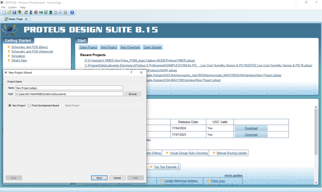
- Open Proteus & Create New Project and click next
- Click on Pick Device
- Search for PIC16F877A & L9110 & DC MOTOR
- Click on Virtual Instruments Mode then choose TERMINAL
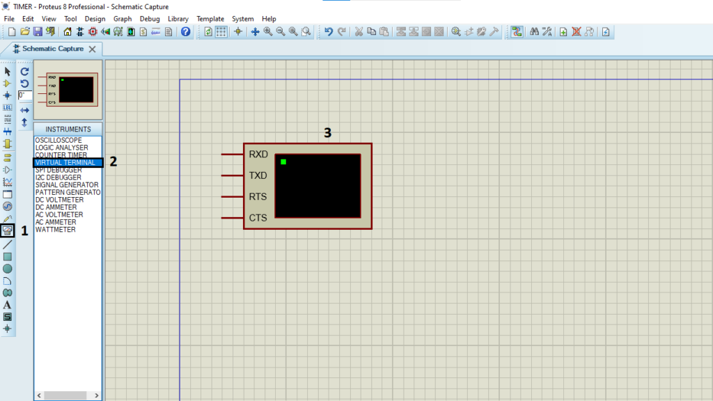
- Click on Terminal Mode then choose (DEFAULT & POWER &GROUND)
- finally make the circuit below and start the simulation
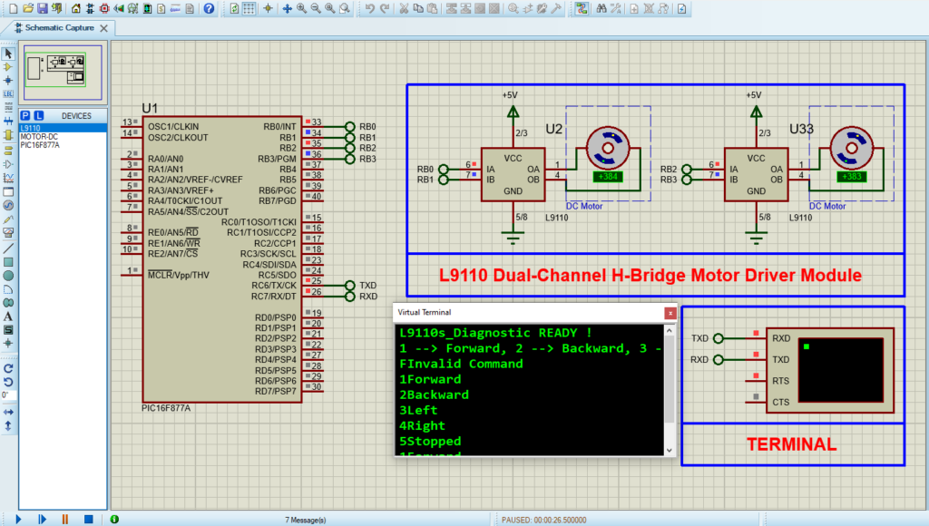
That’s all!
If you have any questions or suggestions don’t hesitate to leave a comment below
