In this article, explore how to use the PIC16F877A microcontroller with the INA219AID sensor for energy monitoring and power measurement applications.

INA219AID-Based Energy Monitoring System: A Step-by-Step Guide
In this project, we will demonstrate how to interface the INA219AID current sensor with the PIC16F877A microcontroller to build a precise energy monitoring system for power measurement and analysis.
INA219AID Overview
The INA219AID is a high-precision, bidirectional current and power monitor with an I²C-compatible interface. Designed for applications requiring accurate current, voltage, and power measurements, this device is widely used in power management, battery monitoring, and energy-efficient systems. Its ability to measure both shunt voltage and bus voltage makes it a versatile solution for a variety of industrial and consumer electronics applications.
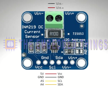
INA219AID Features and Applications
Key Features:
- Wide Voltage Range: The INA219AID can sense bus voltages from 0 to 26 V, making it suitable for low-voltage and medium-voltage systems.
- High Accuracy: With a maximum error of 0.5% over temperature, it ensures reliable and precise measurements.
- Programmable Calibration: The device allows users to calibrate the measurement system for improved accuracy and flexibility.
- I²C Interface: The 16 programmable addresses enable easy integration into multi-device systems.
- Compact Packages: Available in SOT23-8 and SOIC-8 packages, it is ideal for space-constrained designs.
Applications:
- Power Management: Used in servers, telecom equipment, and power supplies to monitor energy consumption.
- Battery Monitoring: Ideal for tracking charge and discharge cycles in battery-powered devices.
- Test Equipment: Provides accurate measurements for debugging and validation in lab environments.
- Industrial Automation: Ensures efficient energy usage in welding equipment and other industrial systems.
INA219AID Diagram
The INA219AID is a highly versatile and precise current, voltage, and power monitoring device, designed for a wide range of applications. Below is a summary of its key features and functionalities:
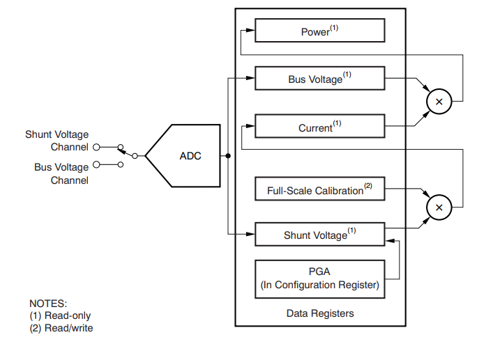
Shunt Voltage Measurement
- Measures voltage drop across a low-value shunt resistor in the current path.
- Voltage drop (millivolt range) is proportional to the current flowing through the resistor.
- Utilizes a high-resolution ADC for accurate digitization of small voltages.
- Key Benefit: Shunt resistor can be placed on either the high side (between power supply and load) or low side (between load and ground), offering design flexibility.
- Accuracy: Supports a wide range of shunt resistor values, enabling customization for different current levels while maintaining precision.
Bus Voltage Measurement
- Monitors the supply voltage (bus voltage) relative to ground.
- Wide Range: Programmable measurement range up to 26 V, suitable for battery-powered or solar-powered systems.
- Integration: Combines bus voltage and shunt voltage measurements to calculate real-time power consumption.
I²C Interface
- Enables seamless communication with microcontrollers or other I²C-compatible devices.
- 16 Programmable Addresses: Supports multi-device operation on the same I²C bus, ideal for multi-channel monitoring systems.
- Ease of Use: Compatible with standard I²C protocols for easy integration.
- Data Registers: Dedicated registers store current, voltage, and power measurements for easy access via I²C.
Programmable Gain Amplifier (PGA)
- Adjustable gain settings (1x, 2x, 4x, or 8x) to handle shunt voltage ranges from ±40 mV to ±320 mV.
- Optimization: Maximizes ADC resolution for specific applications, ensuring accurate measurements even at low current levels.
- 5. Internal Multiplier for Power Calculation
Calculates power consumption internally by multiplying measured current (from shunt voltage) by bus voltage. - Efficiency: Eliminates the need for external calculations or additional components, reducing system complexity and improving response time.
Calibration Register
- Allows fine-tuning of current and power measurement scales to match system requirements.
- Error Reduction: Minimizes measurement errors caused by variations in shunt resistor values or system parameters.
Thermal and Electrical Protection
- Wide Temperature Range: Operates reliably from -40°C to 125°C, suitable for industrial and automotive applications.
- Overvoltage Protection: Handles common-mode voltages up to 26 V, ensuring durability in high-voltage systems.
Project: Interfacing INA219 Current Sensor with PIC16F877A Microcontroller
This project demonstrates how to interface the INA219 current sensor with a PIC16F877A microcontroller to measure voltage, current, and power in real-time. The system uses UART communication to display sensor data, including bus voltage, shunt voltage, current, and power, for easy monitoring and debugging. Below is a detailed explanation of the code files used in the project:
Main Header File (main.h)
This header file defines configuration bits, constants, and includes necessary libraries for the project. It also sets the oscillator frequency for the PIC microcontroller.
#ifndef MAIN_H
#define MAIN_H

#include <xc.h>
#include <stdlib.h> // For atoi function to convert text to integer
#include <stdio.h>
#include <stdbool.h>

#define _XTAL_FREQ 16000000 // Oscillator Frequency (16MHz)

#endif
UART Header File (uart.h)
This header file defines the UART functions for initializing and handling serial communication between the PIC microcontroller and an external device (e.g., a PC or another microcontroller).
#ifndef UART_H
#define UART_H
#include "main.h"

// Function prototypes
void UART_TX_Init(void);              // Initialize UART for transmission
uint8_t UART_TX_Empty(void);          // Check if UART transmit buffer is empty
void UART_Write(uint8_t data);        // Write a single byte to UART
void UART_Write_Text(const char* text); // Write a string to UART
uint8_t UART_Read(void);              // Read a single byte from UART
void UART_Read_Text(char* buffer, uint8_t max_length); // Read a string from UART

#endif // UART_H
I2C Header File (i2c.h)
This header file defines the I2C functions for communication between the PIC microcontroller and the INA219 sensor. It includes initialization, start/stop conditions, and data read/write functions.
#ifndef I2C_H
#define I2C_H
#include "main.h"

// Define constants
#define I2C_BaudRate 100000           // I2C Baud Rate (100 kHz)
#define SCL_D TRISC3                  // SCL Pin Direction
#define SDA_D TRISC4                  // SDA Pin Direction

// Function prototypes
void I2C_Master_Init(void);           // Initialize I2C Master
void I2C_Master_Wait(void);           // Wait for I2C operation to complete
void I2C_Master_Start(void);          // Send I2C Start condition
void I2C_Master_RepeatedStart(void);  // Send I2C Repeated Start condition
void I2C_Master_Stop(void);           // Send I2C Stop condition
void I2C_ACK(void);                   // Send I2C Acknowledge
void I2C_NACK(void);                  // Send I2C Not Acknowledge
unsigned char I2C_Master_Write(unsigned char data); // Write a byte to I2C
unsigned char I2C_Read_Byte(void);    // Read a byte from I2C

#endif
INA219 Header File (INA219.h)
This header file defines the INA219 sensor’s register addresses, configuration masks, and function prototypes for initializing and reading sensor data.
#ifndef INA219_H
#define INA219_H

#include <stdint.h>
#include "i2c.h"

// INA219 I2C Address
#define INA219_ADDRESS 0x40

// Register Addresses
#define INA219_REG_CONFIG 0x00
#define INA219_REG_SHUNTVOLTAGE 0x01
#define INA219_REG_BUSVOLTAGE 0x02
#define INA219_REG_POWER 0x03
#define INA219_REG_CURRENT 0x04
#define INA219_REG_CALIBRATION 0x05

// Configuration Register Masks
#define INA219_CONFIG_RESET 0x8000
#define INA219_CONFIG_BVOLTAGERANGE_MASK 0x2000
#define INA219_CONFIG_GAIN_MASK 0x1800
#define INA219_CONFIG_BADCRES_MASK 0x0780
#define INA219_CONFIG_SADCRES_MASK 0x0078
#define INA219_CONFIG_MODE_MASK 0x0007

// Function Prototypes
bool INA219_Init(void);               // Initialize INA219 sensor
float INA219_GetBusVoltage_V(void);   // Get bus voltage in volts
float INA219_GetShuntVoltage_mV(void); // Get shunt voltage in millivolts
float INA219_GetCurrent_mA(void);     // Get current in milliamperes
float INA219_GetPower_mW(void);       // Get power in milliwatts
void INA219_PowerSave(bool on);       // Enable/disable power save mode

#endif // INA219_H
Main Source File (main.c)
This file contains the main logic for reading data from the INA219 sensor and transmitting it over UART for monitoring. It initializes the UART and I2C interfaces, reads sensor values, and displays them in a user-friendly format.
#include "main.h"
#include "INA219.h"
#include "uart.h"

void main(void) {
    // Variables to hold sensor values
    float shuntVoltage = 0.0;
    float busVoltage = 0.0;
    float current_mA = 0.0;
    float loadVoltage = 0.0;
    float power_mW = 0.0;

    char buffer[64];

    // Initialization
    UART_TX_Init();     // Initialize UART for debugging
    INA219_Init();      // Initialize INA219 sensor

    UART_Write_Text("Measuring voltage and current with INA219 ... \n\r");

    while (1) {
        // Read INA219 sensor values
        shuntVoltage = INA219_GetShuntVoltage_mV();
        busVoltage   = INA219_GetBusVoltage_V();
        current_mA   = INA219_GetCurrent_mA();
        power_mW     = INA219_GetPower_mW();
        loadVoltage  = busVoltage + (shuntVoltage / 1000.0);

        // Format and transmit readings over UART
        sprintf(buffer, "Bus Voltage:   %.2f V\n\r", busVoltage);
        UART_Write_Text(buffer);

        sprintf(buffer, "Shunt Voltage: %.2f mV\n\r", shuntVoltage);
        UART_Write_Text(buffer);

        sprintf(buffer, "Load Voltage:  %.2f V\n\r", loadVoltage);
        UART_Write_Text(buffer);

        sprintf(buffer, "Current:       %.2f mA\n\r", current_mA);
        UART_Write_Text(buffer);

        sprintf(buffer, "Power:         %.2f mW\n\r", power_mW);
        UART_Write_Text(buffer);

        UART_Write_Text("-----------------------------\n\r");

        __delay_ms(2000); // Delay for 2 seconds
    }
}
Proteus Configuration :
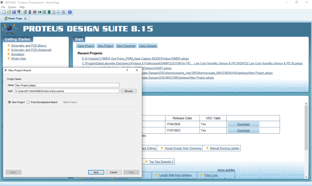
- Open Proteus & Create New Project and click next
- Click on Pick Device
- Search for PIC16F877A & INA219AID & POTENTIOMETRE & RES
- Click on Virtual Instruments Mode then choose TERMINAL
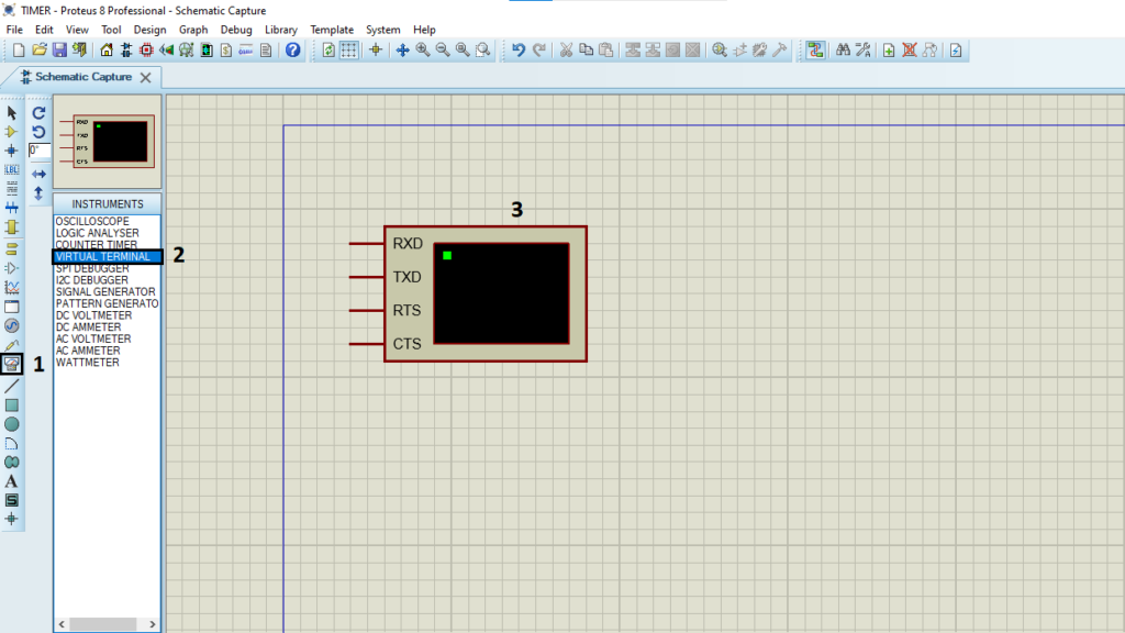
- Click on Terminal Mode then choose (DEFAULT & POWER &GROUND)
- finally make the circuit below and start the simulation
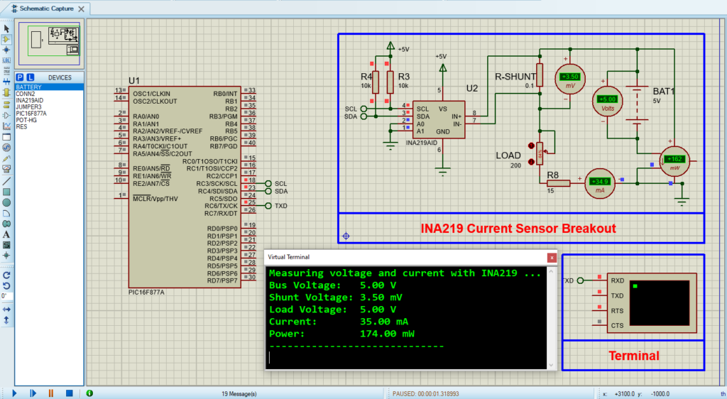
That’s all!
If you have any questions or suggestions don’t hesitate to leave a comment below
