In this article, learn how to interface the FDC1004 with the PIC16F877A for precise capacitance sensing and easy project integration.
Interfacing the FDC1004 Capacitance-to-Digital Converter with the PIC16F877A Microcontroller: A Comprehensive Guide for Precision Capacitive Sensing Applications
In this project, we will explore how to interface the FDC1004 capacitance-to-digital converter with the PIC16F877A microcontroller. The FDC1004 is a high-precision sensor with I2C communication, ideal for applications like capacitance sensing, proximity detection, and liquid level measurement in embedded systems.
FDC1004 Overview
The FDC1004 is a high-resolution, 4-channel capacitance-to-digital converter tailored for capacitive sensing applications. It excels in measuring small capacitance changes with precision, making it ideal for tasks such as proximity detection and liquid level monitoring. Its compact design and low power consumption make it a versatile choice for embedded systems requiring accurate and reliable capacitance measurements.
The device converts capacitance changes into digital data, which can be easily processed by microcontrollers or other digital systems. It is capable of handling large offset capacitances (up to 100 pF) and features integrated shield drivers, making it suitable for both remote and direct sensing applications. The FDC1004 is particularly effective in environments where traditional sensing methods may be challenged by noise or environmental interference.
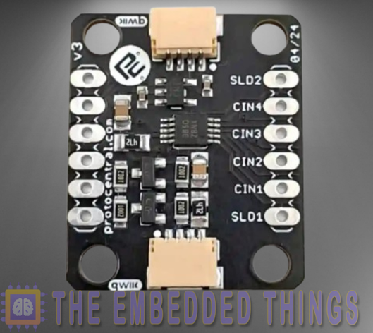
FDC1004Features and Applications
Key Features:
- High Resolution: The FDC1004 offers a measurement resolution of 0.5 fF, allowing it to detect even the smallest capacitance changes.
- Wide Input Range: It supports a capacitance input range of ±15 pF, with the ability to handle offset capacitances up to 100 pF.
- Low Power Consumption: With an active current of 750 µA and standby current of 29 µA, the FDC1004 is optimized for power-sensitive applications.
- Integrated Shield Drivers: Shield drivers reduce electromagnetic interference (EMI) and improve the accuracy of capacitance measurements.
- I2C Interface: The device communicates via an I2C interface, making it easy to integrate with microcontrollers and other digital systems.
- Temperature Stability: The FDC1004 operates reliably across a wide temperature range of -40°C to 125°C, making it suitable for harsh environments.
Applications:
- Proximity Sensing: Detect the presence of objects without physical contact, ideal for touchless interfaces and security systems.
- Liquid Level Monitoring: Measure liquid levels in non-conductive containers, useful in industrial and automotive applications.
- Gesture Recognition: Enable gesture-based controls in consumer electronics and smart devices.
- Material Analysis: Detect material properties such as thickness, density, or composition.
- Automotive Sensors: Implement rain sensors, door handle detection, and other automotive sensing solutions.
FDC1007 Block Diagram
The FDC1004’s internal architecture is designed to provide accurate and reliable capacitance measurements. Below is a simplified block diagram of its key components:
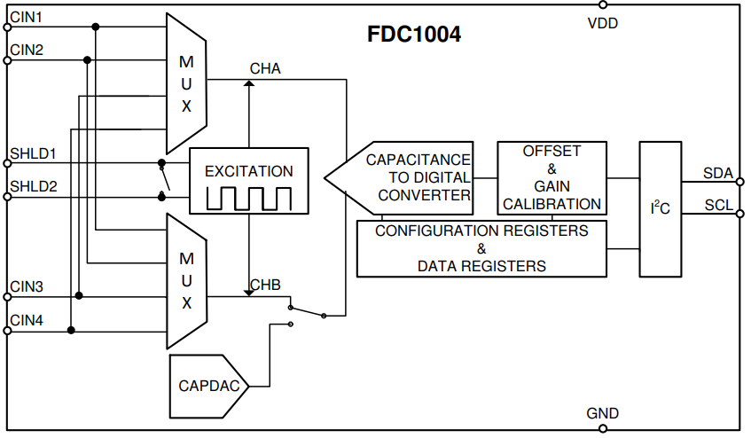
- Capacitance Inputs (CIN1-CIN4): These pins connect to the capacitive sensors. Each channel can measure capacitance relative to ground.
- Shield Drivers (SHLD1, SHLD2): These outputs drive shielding electrodes to reduce noise and improve measurement accuracy.
- Capacitance-to-Digital Converter (CDC): The core of the FDC1004, this block converts capacitance changes into digital data.
- I2C Interface: Facilitates communication with external microcontrollers or processors.
- Power Management: Ensures stable operation with a supply voltage range of 3.0V to 3.6V.
Why Choose the FDC1004?
The FDC1004 excels in capacitive sensing due to its versatility, ease of integration, and robust performance in challenging environments. It handles large offset capacitances and features integrated shield drivers, ensuring reliable operation despite factors like temperature, humidity, or EMI.
A key highlight is its programmable output rates (100, 200, or 400 samples per second), offering flexibility to balance resolution and speed for diverse applications. For instance, liquid level sensing may require lower sample rates, while gesture recognition benefits from faster sampling for real-time responsiveness.
The FDC1004’s compact design (available in 10-pin WSON and VSSOP packages) suits space-constrained systems, and its low power consumption makes it ideal for battery-powered or energy-efficient applications. These features make the FDC1004 a standout choice for precise and reliable capacitive
Project: Interfacing FDC1004 Capacitance Sensor with PIC Microcontroller and LCD Display
This project demonstrates how to interface the FDC1004 capacitance-to-digital converter with a PIC microcontroller using the I2C communication protocol. The system reads capacitance data from the FDC1004 and displays it on an LCD screen in real-time. Below is a detailed explanation of the code files used in the project:
I2C Driver Header File (i2c.h)
This header file defines the I2C driver functions for initializing and handling I2C communication between the microcontroller and the FDC1004 sensor.
#ifndef I2C_H
#define I2C_H

#include <xc.h>
#include <math.h>
#include <stdint.h>
#include <stdio.h>  // For sprintf

#define _XTAL_FREQ             16000000
#define I2C_BaudRate           100000
#define SCL_D                  TRISC3
#define SDA_D                  TRISC4

// Function prototypes
void I2C_Master_Init(void);
void I2C_Master_Wait(void);
void I2C_Master_Start(void);
void I2C_Master_RepeatedStart(void);
void I2C_Master_Stop(void);
void I2C_ACK(void);
void I2C_NACK(void);
unsigned char I2C_Master_Write(unsigned char data);
unsigned char I2C_Read_Byte(void);

#endif
LCD Driver Header File (lcd.h)
This header file defines functions for initializing and controlling the LCD display, including sending commands and printing text.
#ifndef LCD_H
#define LCD_H

#include "i2c.h"

#define RS PORTCbits.RC0  // Register Select pin
#define RW PORTCbits.RC1  // Read/Write pin
#define EN PORTCbits.RC2  // Enable pin

// Function Prototypes
void lcd_initialize(void);
void lcd_data(unsigned char data);
void lcd_string(const unsigned char *str, unsigned char len);
void lcd_command(unsigned char cmd);

#endif /* LCD_H */
FDC1004 Driver Header File (FDC1004.h)
This header file defines constants, configurations, and function prototypes for interacting with the FDC1004 sensor. It includes settings for sample rates, channels, and capacitance measurement.
#ifndef FDC1004_H
#define FDC1004_H
#include "i2c.h"

#include <xc.h>
#include <stdint.h>

// Constants and limits for FDC1004
#define FDC1004_100HZ (0x01)
#define FDC1004_200HZ (0x02)
#define FDC1004_400HZ (0x03)
#define FDC1004_IS_RATE(x) (x == FDC1004_100HZ || x == FDC1004_200HZ || x == FDC1004_400HZ)

#define FDC1004_CAPDAC_MAX (0x1F)
#define FDC1004_CHANNEL_MAX (0x03)
#define FDC1004_IS_CHANNEL(x) (x >= 0 && x <= FDC1004_CHANNEL_MAX)

#define FDC1004_MEAS_MAX (0x03)
#define FDC1004_IS_MEAS(x) (x >= 0 && x <= FDC1004_MEAS_MAX)

#define FDC_REGISTER (0x0C)

// Measurement scaling constants
#define ATTOFARADS_UPPER_WORD (488)
#define FEMTOFARADS_CAPDAC (3125)

typedef struct {
    int16_t value;
    uint8_t capdac;
} fdc1004_measurement_t;

typedef struct {
    uint8_t address;
    uint8_t rate;
    uint8_t last_capdac[4];
} FDC1004;

// Function prototypes
void FDC1004_Init(FDC1004 *fdc, uint8_t rate);
uint8_t FDC1004_ConfigureMeasurement(FDC1004 *fdc, uint8_t measurement, uint8_t channel, uint8_t capdac);
uint8_t FDC1004_TriggerMeasurement(FDC1004 *fdc, uint8_t measurement, uint8_t rate);
uint8_t FDC1004_ReadMeasurement(FDC1004 *fdc, uint8_t measurement, uint16_t *value);
uint8_t FDC1004_MeasureChannel(FDC1004 *fdc, uint8_t channel, uint8_t capdac, uint16_t *value);
int32_t FDC1004_GetCapacitance(FDC1004 *fdc, uint8_t channel);
uint8_t FDC1004_GetRawCapacitance(FDC1004 *fdc, uint8_t channel, fdc1004_measurement_t *value);

#endif /* FDC1004_H */
Main Application File (main.c)
This file initializes the hardware, reads capacitance data from the FDC1004 sensor, and displays it on the LCD. It also handles dynamic adjustment of the CAPDAC to ensure accurate measurements.
#include "i2c.h"
#include "lcd.h"
#include "FDC1004.h"

#define UPPER_BOUND  0x4000
#define LOWER_BOUND  (-1 * UPPER_BOUND)
#define CHANNEL_1 0
#define MEASUREMENT_1 0

#define CHANNEL_2 1
#define MEASUREMENT_2 1

void main(void) {
    FDC1004 fdc;
    uint16_t value_1[2], value_2[2];
    int capdac_1 = 0, capdac_2 = 0;

    // Initialize I2C and LCD
    I2C_Master_Init();
    lcd_initialize();
    FDC1004_Init(&fdc, FDC1004_400HZ);

    while (1) {
        // Configure and trigger a single measurement for Channel 1
        FDC1004_ConfigureMeasurement(&fdc, MEASUREMENT_1, CHANNEL_1, capdac_1);
        FDC1004_TriggerMeasurement(&fdc, MEASUREMENT_1, FDC1004_100HZ);

        if (!FDC1004_ReadMeasurement(&fdc, MEASUREMENT_1, value_1)) {
            int16_t msb_1 = (int16_t)value_1[0];
            int32_t capacitance_1 = ((int32_t)457) * ((int32_t)msb_1); // in attofarads
            capacitance_1 /= 1000; // in femtofarads
            capacitance_1 += ((int32_t)3028) * ((int32_t)capdac_1);

            // Display capacitance for Channel 1 on the LCD
            char buffer_1[16];
            sprintf(buffer_1, "C1=%.4f pF", (float)capacitance_1 / 1000);
            lcd_command(0x80); // Move to the first line
            lcd_string((const unsigned char *)buffer_1, sizeof(buffer_1));

            // Adjust capdac if necessary for Channel 1
            if (msb_1 > UPPER_BOUND) {
                if (capdac_1 < FDC1004_CAPDAC_MAX)
                    capdac_1++;
            } else if (msb_1 < LOWER_BOUND) {
                if (capdac_1 > 0)
                    capdac_1--;
            }
        }
    }
}
Proteus Configuration :
- Open Proteus & Create New Project and click next
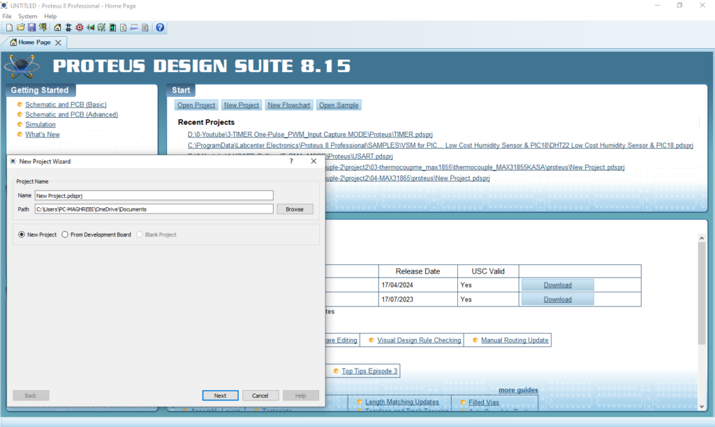
- Click on Pick Device
- Search for PIC16F877A & FDC1004 & LCD 16X2 1RESISTOR & CAPA
- Click on Virtual Instruments Mode then choose I2C DEBUGGER

- Click on Terminal Mode then choose (DEFAULT & POWER &GROUND)
- finally make the circuit below and start the simulation
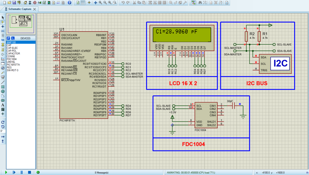
That’s all!
If you have any questions or suggestions don’t hesitate to leave a comment below
