PIC16F877 with I2C 16×2 LCD: A Complete Step-by-Step Guide

by Marwen Maghrebi

In this article, we will explore interfacing the PIC16F877 with an I2C 16×2 LCD. You’ll learn how to connect the microcontroller to the LCD for efficient data display.

Key features of the project interfacing PIC16F877A with a I2C 16×2 LCD.

Things used in this project

Software apps and online services:

1- MPLAB

2- Proteus 8

Interfacing I2C LCD 16×2 With PIC16F877A Microcontroller

Microcontrollers serve as the brains of many embedded systems, handling tasks ranging from simple automation to complex control. By interfacing the PIC16F877 with an I2C 16×2 LCD, you enhance its functionality. The I2C protocol simplifies this process, enabling efficient communication between microcontrollers and peripherals. Focusing on the interfacing of the PIC16F877 with I2C 16×2 LCD modules streamlines your projects, offering convenience and flexibility.

I2C LCD IO Expander (PCF8574):

Module Board Description & Pinout

The I2C LCD IO Expander (PCF8574) module board serves as a breakout board for the PCF8574 chip, facilitating LCD interfacing through a 16-pin header. It features a jumper to toggle the LCD backlight and a potentiometer for adjusting the LCD screen contrast.

The solder pads labeled A0, A1, and A2 allow you to configure the address of the board by soldering these pads to set different address bits. This enables multiple LCD I2C expander boards on the same bus. The module board also includes a power indicator, voltage regulator, and a header for connecting the I2C 2-wire interface (SCL, SDA).

I2C LCD IO Expander (PCF8574) module board for interfacing PIC16F877 with I2C 16x2 LCD, featuring a 16-pin header and adjustable backlight.

PCF8574 I2C IO Expander

The PCF8574/74A serves as a general-purpose remote I/O expansion device via the two-wire bidirectional I2C-bus (SCL, SDA) operating at 100 kHz. This device allows the system master to read from the input port or write to the output port through a single register.

The PCF8574 and PCF8574A are functionally identical, except for their fixed slave address portions. Utilizing the three hardware address pins, up to eight devices of each type can coexist on the same I2C-bus, supporting a maximum of 128 I/Os.

An active LOW open-drain interrupt output (INT) is provided, which can be connected to the microcontroller’s interrupt logic. This feature is activated when any input state differs from its corresponding input port register state, signaling to the microcontroller that an input state has changed.

Features of PCF8574:

  • I2C-bus to parallel port expander
  • Standard-mode I2C-bus interface operating at 100 kHz
  • Operating supply voltage ranging from 2.5 V to 6 V
  • 8-bit remote I/O pins defaulting to inputs at power-up
  • Latched outputs capable of directly driving LEDs
  • Total package sink capability of 80 mA
  • Active-LOW open-drain interrupt output
  • Eight programmable slave addresses using three address pins
  • Low standby current consumption (2.5 µA typical)

Applications for PCF8574:

  • LEDs and displays
  • Servers
  • Keypads
  • Industrial control systems
  • Programmable logic controllers (PLCs)
  • Cellular phones
  • Instrumentation and test measurement equipment

I2C Device Address Configuration:

The PCF8574/74A utilizes a slave address format following a START condition, where the address of the slave and the desired operation (read or write) are sent by the bus master.

The device’s address pins (A2, A1, A0) can be connected directly to VDD or VSS or through external resistors to set the address bits.

PCF8574/74A I2C address configuration for interfacing with PIC microcontrollers, highlighting address pins A2, A1, and A0

PCF8574 I2C Device Address Configuration and IO Programming

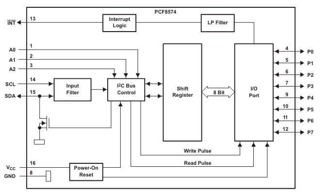
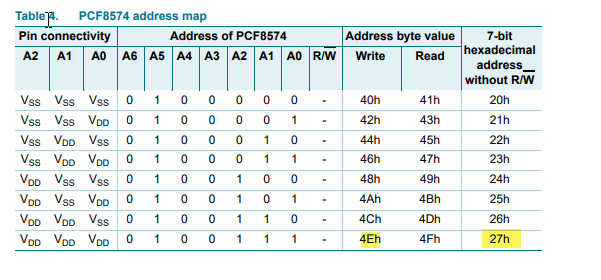
The PCF8574/74A utilizes a slave address format following a START condition, where the bus master sends the address of the slave and the desired operation (read or write). The device’s address pins (A2, A1, A0) can be connected directly to VDD or VSS, or through external resistors, to configure the address bits. This configuration allows for flexible addressing in various applications. The PCF8574 features quasi-bidirectional I/Os, functioning as input or output ports without needing a separate direction control register. Upon power-on, all ports default to a HIGH state, maintained by a weak 100 µA internal pull-up to VDD, but can be driven LOW by an internal transistor or an external signal.

In write mode, the master sends the slave address with the last bit set to logic 0, followed by the data byte for ports P7 to P0. Writing a LOW pulls the port down, while writing a HIGH activates a pull-up for half of the clock cycle before being held HIGH by a weak current source. To read from a port, the master addresses the slave device and sets the last bit of the address byte to logic 1. The slave acknowledges and sends the data byte to the master, which can then ACK or NACK and read the input register again. Reading an output pin indicates its actual state, either HIGH or LOW, providing a straightforward method for input and output operations.

Project name : I2C LCD Interface with PIC16F877A

This project demonstrates an advanced LCD interface for the PIC16F877A microcontroller using the PCF8574 I2C I/O expander. It facilitates the communication between the microcontroller and the LCD, enabling various display operations such as initialization, clearing the screen, printing messages, and controlling the cursor.

Code (in C using XC8 Compiler):

Initialization and Configuration

This part covers the necessary includes, configuration settings, and the initial setup for the PIC microcontroller. It establishes the constants for I2C communication and LCD commands, and it also defines the function prototypes.

/* File: main.c
 * Author: Marwen Maghrebi
 * Description: Advanced LCD Interface for PIC16F877A Using PCF8574
 * This code demonstrates an enhanced interface for LCD (Liquid Crystal Display) with a PIC microcontroller, specifically the PIC16F877A, 
 *utilizing the PCF8574 I2C I/O expander. It initializes the LCD, clears the screen, and prints messages. Additionally, it provides functions 
 *to control the cursor position, send commands or data to the LCD, and manage the backlight.
 */

// Include necessary header files
#include <xc.h>

// Define constants
#define _XTAL_FREQ             16000000
#define I2C_BaudRate           100000
#define SCL_D                  TRISC3
#define SDA_D                  TRISC4

#define LCD_BACKLIGHT          0x08
#define LCD_NOBACKLIGHT        0x00
#define LCD_FIRST_ROW          0x80
#define LCD_SECOND_ROW         0xC0
#define LCD_THIRD_ROW          0x94
#define LCD_FOURTH_ROW         0xD4
#define LCD_CLEAR              0x01
#define LCD_RETURN_HOME        0x02
#define LCD_ENTRY_MODE_SET     0x04
#define LCD_CURSOR_OFF         0x0C
#define LCD_UNDERLINE_ON       0x0E
#define LCD_BLINK_CURSOR_ON    0x0F
#define LCD_MOVE_CURSOR_LEFT   0x10
#define LCD_MOVE_CURSOR_RIGHT  0x14
#define LCD_TURN_ON            0x0C
#define LCD_TURN_OFF           0x08
#define LCD_SHIFT_LEFT         0x18
#define LCD_SHIFT_RIGHT        0x1E
#define LCD_TYPE               2       // 0 -> 5x7 | 1 -> 5x10 | 2 -> 2 lines

// Function prototypes
void main(void);
void I2C_Master_Init(void);
void I2C_Master_Wait(void);
void I2C_Master_Start(void);
void I2C_Master_RepeatedStart(void);
void I2C_Master_Stop(void);
void I2C_ACK(void);
void I2C_NACK(void);
unsigned char I2C_Master_Write(unsigned char data);
unsigned char I2C_Read_Byte(void);

LCD Control Functions

This part provides the functions necessary for interacting with the LCD. It includes commands for initializing the LCD, writing data and commands, controlling the cursor, and managing backlight settings.

void LCD_Init(unsigned char I2C_Add) 
{
    i2c_add = I2C_Add;
    IO_Expander_Write(0x00);
    __delay_ms(30);
    LCD_CMD(0x03);
    __delay_ms(5);
    LCD_CMD(0x03);
    __delay_ms(5);
    LCD_CMD(0x03);
    __delay_ms(5);
    LCD_CMD(LCD_RETURN_HOME);
    __delay_ms(5);
    LCD_CMD(0x20 | (LCD_TYPE << 2));
    __delay_ms(50);
    LCD_CMD(LCD_TURN_ON);
    __delay_ms(50);
    LCD_CMD(LCD_CLEAR);
    __delay_ms(50);
    LCD_CMD(LCD_ENTRY_MODE_SET | LCD_RETURN_HOME);
    __delay_ms(50);
}

void IO_Expander_Write(unsigned char Data) 
{
    I2C_Master_Start();
    I2C_Master_Write(i2c_add);
    I2C_Master_Write(Data | BackLight_State);
    I2C_Master_Stop();
}

void LCD_Write_4Bit(unsigned char Nibble) 
{
    // Get The RS Value To LSB OF Data  
    Nibble |= RS;
    IO_Expander_Write(Nibble | 0x04);
    IO_Expander_Write(Nibble & 0xFB);
    __delay_us(50);
}

void LCD_CMD(unsigned char CMD) 
{
    RS = 0; // Command Register Select
    LCD_Write_4Bit(CMD & 0xF0);
    LCD_Write_4Bit((CMD << 4) & 0xF0);
}

void LCD_Print_Char(char Data)
{
    RS = 1;  // Data Register Select
    LCD_Write_4Bit(Data & 0xF0);
    LCD_Write_4Bit((Data << 4) & 0xF0);
}

void LCD_Print_String(char* Str)
{
    for(int i=0; Str[i]!='\0'; i++)
       LCD_Print_Char(Str[i]); 
}

void LCD_Set_Cursor(unsigned char ROW, unsigned char COL) 
{    
    switch(ROW) 
    {
        case 2:
            LCD_CMD(0xC0 + COL-1);
            break;
        case 3:
            LCD_CMD(0x94 + COL-1);
            break;
        case 4:
            LCD_CMD(0xD4 + COL-1);
            break;
        default:
            LCD_CMD(0x80 + COL-1);
    }
}

void Backlight(void) 
{
    BackLight_State = LCD_BACKLIGHT;
    IO_Expander_Write(0);
}

void noBacklight(void) 
{
    BackLight_State = LCD_NOBACKLIGHT;
    IO_Expander_Write(0);
}

void LCD_SL(void)
{
    LCD_CMD(0x18);
    __delay_us(40);
}

void LCD_SR(void)
{
    LCD_CMD(0x1C);
    __delay_us(40);
}

void LCD_Clear(void)
{
    LCD_CMD(0x01); 
    __delay_us(40);
}

Main Function and I2C Communication

In this section, we focus on the main function that initializes the LCD and writes strings to it. We also define the I2C communication functions, including starting, stopping, and writing data.

// PIC16F877A Configuration Bit Settings
#pragma config FOSC = HS        // Oscillator Selection bits (HS oscillator)
#pragma config WDTE = OFF       // Watchdog Timer Enable bit (WDT disabled)
#pragma config PWRTE = OFF      // Power-up Timer Enable bit (PWRT disabled)
#pragma config BOREN = OFF      // Brown-out Reset Enable bit (BOR disabled)
#pragma config LVP = OFF        // Low-Voltage (Single-Supply) In-Circuit Serial Programming Enable bit (RB3 is digital I/O, HV on MCLR must be used for programming)
#pragma config CPD = OFF        // Data EEPROM Memory Code Protection bit (Data EEPROM code protection off)
#pragma config WRT = OFF        // Flash Program Memory Write Enable bits (Write protection off; all program memory may be written to by EECON control)
#pragma config CP = OFF         // Flash Program Memory Code Protection bit (Code protection off)

unsigned char i2c_add, BackLight_State = LCD_BACKLIGHT;
unsigned char RS;

void main(void) {
    
    // Initialize I2C and LCD
    I2C_Master_Init();
    LCD_Init(0x4E);    // Initialize LCD module with I2C address = 0x4E
 
    // Write strings to LCD
    LCD_Set_Cursor(1, 1);
    LCD_Print_String("  THE EMBEDDED  ");
    LCD_Set_Cursor(2, 1);  
    LCD_Print_String("     THINGS     ");
    __delay_ms(2500);

    // Animation loop
    while(1)
    {
       LCD_SR();
       __delay_ms(350); 
       LCD_SR();
       __delay_ms(350); 
       LCD_SL();
       __delay_ms(350);
       LCD_SL();
       __delay_ms(350);
    }
    return;
}

void I2C_Master_Init(void)
{
    SSPCON  = 0x28;
    SSPCON2 = 0x00;
    SSPSTAT = 0x00;
    SSPADD = ((_XTAL_FREQ/4)/I2C_BaudRate) - 1;
    SCL_D = 1;
    SDA_D = 1; 
}

void I2C_Master_Wait(void)
{
    while ((SSPSTAT & 0x04) || (SSPCON2 & 0x1F));
}

void I2C_Master_Start(void)
{
    I2C_Master_Wait();
    SEN = 1;
}

void I2C_Master_Stop(void)
{
    I2C_Master_Wait();
    PEN = 1;
}

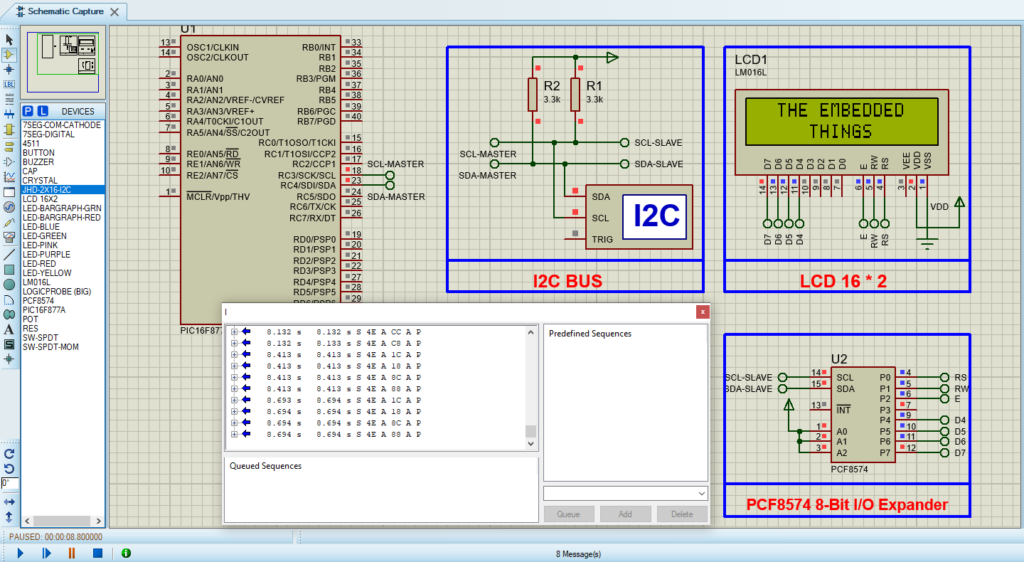
Proteus Configuration :

  • Open Proteus & Create New Project and click next

  • Click on Pick Device
  • Search for PIC16F877A & LCD 16*2 & PCF8574
  • Click on Terminal Mode then choose (DEFAULT & POWER &GROUND)
  • finally make the circuit below and start the simulation
Circuit design for Proteus simulation showing PCF8574/74A I2C configuration with PIC microcontroller and 16x2 LCD.

That’s all!

If you have any questions or suggestions don’t hesitate to leave a comment below

You Might Also Like

Leave a Comment


Are you sure want to unlock this post?
Unlock left : 0
Are you sure want to cancel subscription?
-
00:00
00:00
Update Required Flash plugin
-
00:00
00:00